Mathematical and Software Engineering, Vol. 3, No. 1 (2017), 149-155. Varεpsilon Ltd, varepsilon.com
Computation of Diffraction Parameter as a
Function of Line of Site Percentage Clearance
Nathaniel Chimaobi Nnadi
*
, Charles Chukwuemeka Nnadi, and
Ifeanyi Chima Nnadi
*Corresponding Author: [email protected]
Department of Electrical/Electronic Engineering, Imo State Polytechnic, Umuagwo, Owerri, Nigeria
Abstract
In this paper, mathematical expression and method for computing diffraction parameter as a function of line of site percentage clearance is presented. The concept of line of site percentage clearance scaling factor is introduced. The scaling factor makes it possible to determine the diffraction parameter at different of line of site percentage clearances when the value of diffraction parameter is known at one particular line of site percentage clearance. Particularly, for Fresnel zone n and line of site percentage given as
(,), the diffraction parameter , (, ) is given as (, ) = √(,). Also, for any
two line of site percentages given as (,)() and (,)(), the line of site percentage clearance scaling factor is given as (,)()
(,)(). If the diffraction parameter at (,)()is
given as (, ) , then the diffraction parameter at (,)() is given as (, ) =
(, ) (,)()(,)(). The mathematical expressions and method are applied to a 3 GHz microwave link with path length of 38887.6 m. The results obtained demonstrated the validity of the mathematical expressions and method presented in the paper.
Keywords: Diffraction Parameter; Fresnel Zone; Microwave Link; Percentage
Clearance; Line of Site Communication
1. Introduction
signal frequency, the obstruction height , obstruction location, and the antenna mast height etc. are required. With these parameters, the line of site clearance height is determined along with the diffraction parameter.
Usually, the design specification for LOS link gives the required LOS clearance height in terms of percentage of the radius of the Fresnel zone at any given location along the signal path. In quick link planning situations, it is desired to specify the LOS clearance requirement in terms the of the LOS percentage clearance. In that case, the detailed link and path profile dataset are not required. In this paper, the mathematical expressions that can be used to determine the diffraction parameter as a function of LOS percentage clearance is derived.
Furthermore, in this paper, the concept of LOS percentage clearance scaling factor is introduced. In this case, the LOS percentage clearance enables the diffraction parameter to be determined at any other LOS percentage clearance one the diffraction parameter is known at any one LOS percentage clearance. The derivation and application of the LOS percentage clearance scaling factor are presented in the this paper.
2. Theoretical Background
2.1. The Mathematical Expression for Computing Diffraction Parameter
as a Function of Line of Site Percentage Clearance
For Line Of Site (LOS) communication link the radius of the nth Fresnel zone (()) is given as [5];
()= ʎ !() "() #
!() $ "() (1)
where
%&() is the distance of location x from the transmitter
%'() is the distance of location x from the receiver, where x = 1,2,3,…, N.
N is the number of elevation point in the elevation profile dataset. n is the nth Fresnel zone
λ is the wavelength of the radio wave in metres where;
ʎ = ) (2) where, c is the speed of a radio wave (c = 3x10/0/2 );
f is frequency of the radio wave in Hz.
At any given location x between the transmitter and the receiver, the Fresnel-Kirchoff diffraction parameter is given as() where [5];
() = ℎ()4ʎ !()!() $ "()"()5 (3)
where
ℎ() is effective obstruction clearance height which is the height (in meters) from the
tip of the obstruction at location x to a point on the line of sight at location x, where x is between the transmitter and the receiver.
λ is the wavelength of the radio wave in metres
transmitter. In practice, at least 60% of first Fresnel zone radius, (6) (that is, 0.6 of
(6)) clearance is required to achieve clear line of sight transmission. The percentage clearance specified with respect to () , the radius of any given Fresnel zone n, is denoted as (,) . The line of sight clearance height at point x computed with respect to (,) is denoted as h89:(;,<=) = (,)
() where:
ℎ>?@(, )= A(,) B 4ʎ !()!() $ "()"() # 5 (4)
Hence, for (,) = 60%, ℎ>?@(,E)= 0.6(). In terms of (,) , the Fresnel-Kirchoff diffraction parameter at any given location x between the transmitter and the receiver can be represented as ((, )) and from Eq 3 it is given as: (, ) = ℎ>?@(, )4ʎ !()!() $ "()"()5 (5)
(, ) = A(,) B 4ʎ !()!() $ "()"() # 5 4ʎ !()!() $ "()"()5 (6)
(, ) = A(,) B F√n 4ʎ !()!() $ "()"() # 5H F√2 4ʎ !()!() $ "()"()5H (7)
(, ) = A(,) B √n√2 4ʎ !()!() $ "()"() # ʎ !()!() $ "()"()5 (8)
(, ) = √(,) (9)
(,) =J(,K)√L (10)
For Fresnel zone 1, n=1 , then: (, ) = √(,) (11)
2.2. Line of Site Percentage Clearance Scaling Factor for Computing
Diffraction Parameter
Consider (,)() which denotes the LOS percentage clearance given with respect to a given Fresnel zone, n and (, ) denotes the diffraction parameter computed with respect to (,)(), then: (, ) = √2n A(,)() B (12)Similarly, another LOS percentage clearance, (,)() given with respect to the same Fresnel zone, n , has the diffraction parameter (, )which is given as: (, ) = √2n A(,)() B (13)
The (, ) can be computed with respect to (, ) as follows: J(,K) J(,K) = √LM(,)() NN √LM(,)() NN = (,)() (,)() (14)
Therefore, (,)()
(,)() is the LOS percentage clearance scaling factor for computing
diffraction parameter at different percentage clearance values.
3. Result and Discussion
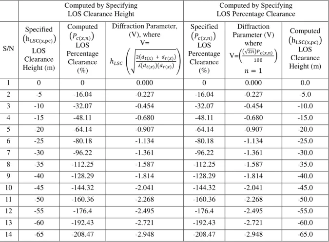
Table 1 shows the diffraction parameter, V, computed by the two methods. The first method is the existing method which uses the LOS clearance height, h89:(;,<=), wavelength , distance from the transmitter and distance from receiver to V. The second approach is the method proposed in this paper which computes V by using only the LOS percentage clearance (,) and the Fresnel zone n with which the percentage clearance is specified . The results in Table 1 is for a link with path length of 38887.6 m . For the LOS percentage clearance in the table , a location at the middle of the link is considered where the distance from the transmitter = distance from receiver = 19443.79 m. The percentage clearance is considered for the first Fresnel zone where n =1. The signal frequency is 3 GHz, speed of light is c = 3x10/0/2 such that the wavelength is 0.1 m. The radius of the first Fresnel zone at the point considered (that is, the middle of the link) is computed as 31.18 m.
Table 1 Diffraction Parameters Computed by the Existing Method and by the New Method
Computed by Specifying LOS Clearance Height
Computed by Specifying LOS Percentage Clearance
S/N
Specified
h89:(;,<=)
LOS Clearance Height (m)
Computed
(,)
LOS Percentage
Clearance (%)
Diffraction Parameter, (V), where
V=
ℎ>?@ OPʎ !()!() $ "()"()Q
Specified
(,)
LOS Percentage
Clearance (%)
Diffraction Parameter (V)
where
V=√(,)
R = 1
Computed
h89:(;,<=)
LOS Clearance Height (m)
1 0 0 0.000 0 0.000 0.0
2 -5 -16.04 -0.227 -16.04 -0.227 -5.0
3 -10 -32.07 -0.454 -32.07 -0.454 -10.0
4 -15 -48.11 -0.680 -48.11 -0.680 -15.0
5 -20 -64.14 -0.907 -64.14 -0.907 -20.0
6 -25 -80.18 -1.134 -80.18 -1.134 -25.0
7 -30 -96.22 -1.361 -96.22 -1.361 -30.0
8 -35 -112.25 -1.587 -112.25 -1.587 -35.0
9 -40 -128.29 -1.814 -128.29 -1.814 -40.0
10 -45 -144.32 -2.041 -144.32 -2.041 -45.0
11 -50 -160.36 -2.268 -160.36 -2.268 -50.0
12 -55 -176.4 -2.495 -176.4 -2.495 -55.0
13 -60 -192.43 -2.721 -192.43 -2.721 -60.0
14 -65 -208.47 -2.948 -208.47 -2.948 -65.0
-48.11%. Conversely, by specifying percentage clearance of -48.11% with respect to the first Fresnel zone, the diffraction parameter obtained is again -0.68 and the LOS clearance height obtained is -15 m.
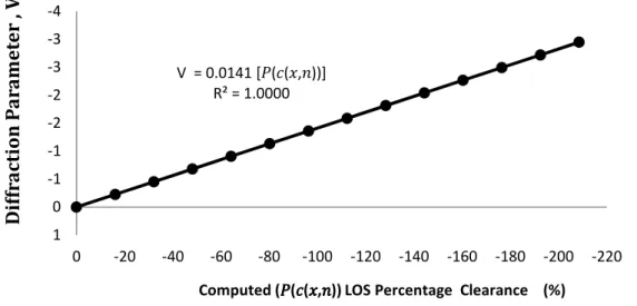
The graph plot of the computed diffraction parameter obtained from the specified LOS clearance and the computed LOS percentage clearance (%) is given in Figure 1. The trendline fitted to the graph shows that
V = 0.0141 S(,)T = .U
S(,)T = √ S(,)T
In this case, the model, V = √
S(,)T is now generated graphically based on the
results obtained when the LOS clearance height is given and then used to compute V and
(,). Essentially, Figure 1 is a graphical validation of the proposed model for
computing the diffraction parameter based on LOS percentage clearance.
Figure 1 The Diffraction Parameter, V, versus Computed (,), LOS Percentage Clearance (%)
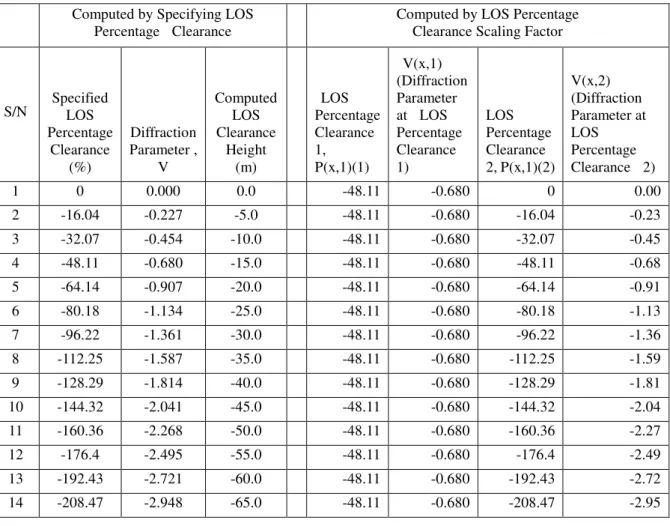
In Table 2, the diffraction parameter is computed for different percentage clearance. Also , the diffraction parameter is computed based on the diffraction parameter at LOS percentage clearance of -48.11%. At -48.11% clearance with respect to Fresnel zone 1 the diffraction parameter is -0.680. At -128.29% clearance with respect to Fresnel zone 1 the diffraction parameter is given as 0.680 AWX.Y
WUX.B = 1.81. The result is the same
as the diffraction loss obtained earlier with -128.29% percentage clearance. In this case, the LOS percentage clearance scaling factor WX.YWUX. is used to determine the diffraction parameter at -128.29% when the diffraction parameter at -48.11% is given as 0.680.
4. Conclusion
Mathematical expression and method for computing diffraction parameter as a function of line of site percentage clearance is presented. Also, the method for computing diffraction parameter at different line of site percentage clearance by using the line of site percentage clearance scaling factor is presented. The ideas presented in this paper make it easier to specify and compute the diffraction parameter and other allied parameters needed in the determination of diffraction loss for line of site communication links.
V = 0.0141 [(Z([,R))] R² = 1.0000 -4
-3
-3
-2
-2
-1
-1
0
1
-220 -200 -180 -160 -140 -120 -100 -80 -60 -40 -20 0
D
if
fr
a
c
ti
o
n
P
a
r
a
m
e
te
r
,
V
Table 2 Validation Result for the LOS Percentage Clearance Scaling Factor
Computed by Specifying LOS Percentage Clearance Computed by LOS Percentage Clearance Scaling Factor
S/N Specified LOS Percentage
Clearance (%)
Diffraction Parameter ,
V
Computed LOS Clearance
Height
(m)
LOS Percentage Clearance 1, P(x,1)(1)
V(x,1) (Diffraction Parameter at LOS Percentage Clearance 1)
LOS Percentage Clearance 2, P(x,1)(2)
V(x,2) (Diffraction Parameter at LOS Percentage Clearance 2)
1 0 0.000 0.0 -48.11 -0.680 0 0.00
2 -16.04 -0.227 -5.0 -48.11 -0.680 -16.04 -0.23
3 -32.07 -0.454 -10.0 -48.11 -0.680 -32.07 -0.45
4 -48.11 -0.680 -15.0 -48.11 -0.680 -48.11 -0.68
5 -64.14 -0.907 -20.0 -48.11 -0.680 -64.14 -0.91
6 -80.18 -1.134 -25.0 -48.11 -0.680 -80.18 -1.13
7 -96.22 -1.361 -30.0 -48.11 -0.680 -96.22 -1.36
8 -112.25 -1.587 -35.0 -48.11 -0.680 -112.25 -1.59
9 -128.29 -1.814 -40.0 -48.11 -0.680 -128.29 -1.81
10 -144.32 -2.041 -45.0 -48.11 -0.680 -144.32 -2.04
11 -160.36 -2.268 -50.0 -48.11 -0.680 -160.36 -2.27
12 -176.4 -2.495 -55.0 -48.11 -0.680 -176.4 -2.49
13 -192.43 -2.721 -60.0 -48.11 -0.680 -192.43 -2.72
14 -208.47 -2.948 -65.0 -48.11 -0.680 -208.47 -2.95
References
[1] Garlington, T. (2006) Microwave Line-of-Sight Transmission Engineering, WP No.
AMSEL-IE-TS-06015.
[2] Dawoud, M.M. (2003) High frequency radiation and human exposure.
In Proceedings of the International Conference on Non-Ionizing Radiation at UNITEN (ICNIR 2003) (pp. 1-7).
[3] Al Mahmud, M.R., Shabbir, Z. (2009) Analysis and planning microwave link to
established efficient wireless communications, Thesis, Blekinge Institute of
Technology.
[4] Brockel, K. ., Barnett, W.T., Chaney, K.D., Inserra, J.R., Locher, R.J., Loso, F.G.,
Procopio, V.J., and Vigants, A. (1991) Tactical line-of-sight radio propagation
reliability, No. CECOM-TR-91-3). Army Communications – Electronics Command, Fort Monmouth, NJ 07703-5203.
[5] Akkasli, C. (2009) Methods for Path loss Prediction, SE-351 95 VÄXJÖ, 09067.
[6] Rao, P.S. (2013) Performance Analysis of Diffraction Gain (Gd) Due to presence of
Knife-Edge as Compared to Free Space E-Field and Identifying the Position of
Obstacle in a Fresnel Zone, International Journal of Scientific and Research
Publications, 3(1), 1-7.
[7] Pelet, E. R., Salt, E. J., Wells, G. (2004, May). Signal distortion caused by tree
foliage in a 2.5 GHz channel. In Electrical and Computer Engineering, 2004.
[8] Klostius, R., Wieser, A., & Brunner, F. K. (2006) Treatment of diffraction effects
caused by mountain ridges. In Proceedings of 3rd IAG/12th FIG Symposium, Baden.
[9] Singh, S., Ziliotto, F., Madhow, U., Belding, E., Rodwell, M. (2009). Blockage and
directivity in 60 GHz wireless personal area networks: From cross-layer model to
multihop MAC design. IEEE Journal on Selected Areas in Communications, 27(8),
1400-1413.
[10]Prasad, M.V.S.N., Bhaskara Rao, S.V., Rama Rao, T., Sarkar, S.K., Sharma, S.
(2004) Double knife edge diffraction propagation studies over irregular
terrain. Indian Journal of Radio & Space Physics, 33(3), 180-184.