Application of IEEE 802.15 to Distribute Cell Phone Calls
through a Home Phone Network
Student Members:
Danny Szczotka
Chris Switzer
Project Advisor: Dr. Liuqing Yang
Graduate Student Advisor: Bo Yu
Department of Electrical and Computer Engineering
Colorado State University
Abstract
Our project, the wireless home phone system, is a wireless bridge device which allows a user to wirelessly connect their cell phone to their landline phone network currently in their home. The device allows the customer to send and receive calls on their existing landline phone without having to pay for the service associated with having a home phone. Especially with recent economic factors, families are looking for ways to reduce expenditures but not lose functionality. This device aims to eliminate the need for the less functional landline phone service, without sacrificing any functionality to the user.
The bridging functions of our device are performed by an Arduino development board, which is connected to a Bluetooth radio and a standard telephone line. The device pairs with a cell phone via a standard Bluetooth connection to ensure compatibility with standard cell phones as well as smartphones. This bridge needs to read in the wireless Bluetooth signal and convert it to an analog signal that a standard home phone can use. In addition, the bridge also needs to convert the analog output from the home phone to a digital format and send to the cell phone via Bluetooth. These two functionalities allow voice transmission over the landline phones without a landline phone service.
Introduction
Millions of people all over the world are currently paying for two or more telephone services: a traditional landline service from a telecom company, and a cellular service from a mobile phone provider. These services are redundant: everything you do on your landline phone can also be accomplished via your cell phone. Even the more basic cell phone subscription plans are becoming cheaper and more flexible, with such features as unlimited talk time to certain numbers, SMS (text) messaging, and others, not to mention the rising popularity of smartphones, which give users additional access to Internet, email, and more.
Especially with the current state of the economy, many people are cutting out landline service altogether in an effort to save hundreds or thousands of dollars per year. As demonstrated below in Figure 1, the number of people who have no landline service is on the rise. There are downsides to “cutting the cord” though. With abysmal battery life on modern smartphones combined with consumers’ busy daily schedules, users are forced to charge their phones whenever they are at home. This forces the phone to stay in one physical location, leading to many missed calls and messages. It also fails to utilize expensive landline phones that people have invested in over the years to provide themselves with the convenience of having a phone in every room of their home.
Figure 1: Graph of people with only wireless service with respect to time [1]
Some people have chosen to combat these drawbacks with voice over Internet protocol (VOIP) services, such as Skype, Vonage, or MagicJack. While these services are alluring because of their low price, they still require monthly fees. Call quality is often lower as well, but the most serious drawback is a lack of security. Because the information is packetized and sent over public Internet servers, conversations are frequently intercepted by unintended recipients [2].
Our device will provide customers with the best of both worlds: high security, low cost, reliable, feature-rich communication with the outside world. It wirelessly communicates with a cell phone and an existing landline network, with minimal invasiveness to the consumer. The device provides all features of both a cell phone and a landline phone, including sending and receiving calls and text messages, allowing users to keep their existing landline telephones to use with their cellular service.
Standards Applied
Bluetooth
Bluetooth (IEEE 802.15) is a wireless technology for short range communication to replace cables that would connect portable and fixed-position electronic devices. The main features of Bluetooth are its low power draw, ease of implementation, and application. According to the official Bluetooth SIG [3], the Bluetooth specification comes in two forms: Basic Rate (BR) and Low Energy (LE). Our focus is on the BR which includes the Enhanced
Data Rate (EDR) extension. The EDR boosts transmission speed from 721.2 kbps to 2.1 Mbps which will be able to handle voice transmission.
Bluetooth operates in the Industrial Scientific and Medical (ISM) band at 2.4 GHz and employs frequency hopping to reduce interference. The frequency hopping is divided into 79 1 MHz blocks between 2.402 and 2.480 GHz, and the radio switches at a rate of 1,600 times per second and is controlled by a common clock.
When devices come in-range of each other, the two radios communicate to attempt to connect although true connection requires the user to enter a passkey based on the Simple Secure Pairing (SSP) aspect of the second revision of the Bluetooth specification (Bluetooth 2.0). After pairing the 2 or more devices are classified as a Personal Area Network (PAN) or piconet. When devices are connected to the piconet, they are done in an ad-hoc manner and can take four positions: master, slave, parked, and standby. The purpose for the master and slave roles is to coordinate the clock for frequency hopping and to assign times when each device is to transmit or receive from the master. The parked position is used when there are more than seven active devices, as this is the limit of devices for a master to be actively connected to. After there are 7 devices active, then next 255 devices to be connected will be parked, or inactive, and the master can activate the parked device at any time. The last position is standby which is default for all devices. The standby mode is a low power mode and is not connected to “any piconet but listens for messages every 1.28 seconds over 32 hop frequencies” [4]
Bluetooth implements a modified version of the OSI Model [4]. As seen the figure below, the Bluetooth core protocols cover up to the Datalink layer of the OSI model and lets the applications handle processing the packets and presentation.
Figure 3: Bluetooth layers related to the OSI model
Bluetooth is special in that it uses profiles to carry out specific tasks. These profiles can be layered to pass functionality without having to encode each profile with redundant features. The Bluetooth Profiles define the required functions and features each layer (RF to RFCOMM/SDP) and how those layers interact from peer to peer. The Generic Access Profile (GAP) defines the basic requirements for a BT device depending on the mode of operation (BR or LE). In addition to the GAP, our device will need to use the Serial Port Profile (SPP) and the Headset Profile (HSP). The SPP generates a transport protocol for data by implementing a serial port emulator [3]. The Headset Profile inherits this emulated port from the SPP and adds a layer for converting voice to BT and adding features such as volume control, call answering, hang up, and voice dial.
Although we chose to use the Hands-Free profile (HFP) over HSP because of its added features such as higher quality audio- 8-bit, 16 KHz vs 8 KHz audio. HFP also allows for features such as voice dialing. The most typical setup for an HFP system is shown below in Figure 4.
Figure 4: Bluetooth channels in a typical wireless headset
The iWRAP protocol of our Bluetooth transceiver supports AT commands to set different profiles and perform basic functions. Shown in the figure above, the HFP commands that are able to be sent from the HFU to the HFP-AG. There are dozens of commands available to send the other direction, not listed below. The commands are sent via an established control channel, which is set up between the Hands-Free Unit and the Audio Gateway.
Landline Phones
Landline phones operate on the Public Switched Telephone Network (PSTN). This network consists of telephone lines, fiber optic cables, cellular networks, communication satellites, and undersea cables to enable communication with any other phone in the world. This network has been undergoing changes since it was created but the biggest move was from analog
to digital systems. Now all the back end operation is controlled digitally but still calls are delivered as an analog signal. When a call is made, the digital systems convert the analog call using 8-bit resolution at 8 kHz using nonlinear pulse code modulation as per the standard G.711 from ITU-T. In the United States, landline phones operate on a 90V sine wave at a -48V DC bias. The -48V bias is to run the ringer for analog phones since the PSTN provides power to phones so calls can still be made even if the power in the home goes out [6].
Modern phones use Dual-Tone Multi-Frequency (DTMF) signaling for placing calls. This system works by mixing two sinusoidal signals. The frequency of the sine waves is dependent on the button being pushed. By mixing these two frequencies one signal can be sent to the switching center which uses a demultiplexer to analyze what button was pushed and rout the call to the correct place. In addition to these tones, there are also dual tones for the dial tone (350 and 440 Hz), ring back tone (440 and 480 Hz), and busy signal (480 and 620 Hz).
Design
Software
The design of the system required applications of hardware and software. We considered several options for a development board, and we chose the Arduino because of its extensive community support, as well as its relatively simple C-based programming language. The most recent version of the Arduino development board is the model called the Arduino Uno R3 [5]. The board provides such features as 14 pins used for input or output, giving us plenty of room to expand and utilize features such as the Bluetooth shield and the RJ-11 breakout board. The Uno also provides six PWM pins, which will be used to transmit analog signal to the landline phone.
A typical Arduino program has a setup stage and a loop stage. The setup stage runs immediately after the unit receives power, and the run stage loops continuously, allowing us to power the unit with an AC adapter rather than via a USB port. We also chose the Arduino because it was compatible with an array of add-on hardware, such as the Bluetooth module.
In the setup stage, the program begins by defining pins to use as transmit and receive, since Bluetooth data transfer is serial and requires one input and one output line. The code sets the device as a Hands-Free Unit (HFU) in the Hands Free profile, which causes a cell phone to recognize the device as a Bluetooth headset. The loop section of the program follows the state diagram for the system, shown below in Figure 5, representing the calling process for a phone.
Figure 5: Software State Diagram
When the device is first powered on, it starts with an Idle state, where the bridge is not paired with a cell phone and the Bluetooth module is searching for a “known” or previously-paired cell phone. Once a cell phone is previously-paired via the Hands Free profile, the system can enter the second state, waiting for either an incoming call from the Bluetooth side, or for the landline phone to be lifted off the hook on the landline side, indicating an outgoing call. Once the landline phone is lifted off the hook, the system enters a stage where it “listens” for numbers pressed on the keypad which create different DTMF tones, and the system interprets those tones as numbers to be dialed out. Once ten numbers have been pressed, the system enters a stage where the number is dialed and the call is connected. If an incoming call is received on the cell phone, the Hands Free profile dictates that a signal is sent to the headset, which puts the system in a state where the landline phone to rings. From that state, if the landline phone is lifted off the hook, the system enters a state where the call is answered and then connected. When in a call, if at any time the landline phone is placed back on the receiver, the call is ended and the system returns to the Idle and Paired state.
Hardware
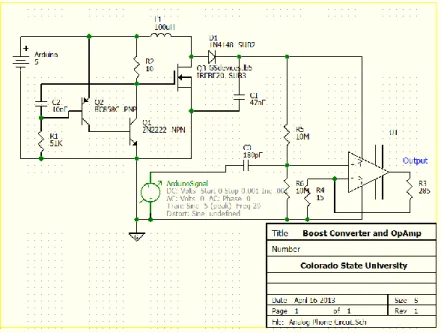
The output from the Arduino board is all digital outputs. Fortunately converting the digital signal to an analog AC signal is possible using Pulse-Width Modulation (PWM). There are 6 PWM pins on the Arduino allow us to simulate an analog signal. To amplify the signal we first need to build a circuit to boost the 5V DC to 115V DC. This is done with a boost converter.
The boost converter uses a variation of a ‘tank’ circuit. A regular tank circuit is a harmonic oscillator. Our boost converter uses a diode and power MOSFET to interrupt the return oscillation and instead, dump excess charge onto the capacitor; this boosts the capacitors voltage since the voltage on the capacitor is equal to the charge divided by its capacitance. So by sending charge from the inductor, across the diode, we are depositing charge onto the capacitor without it being fed back to the inductor because our diode blocks it. With this circuit, we are able to amplify the 5V DC signal to 115V DC.
We used the high voltage coming from the boost converter, to supply our high voltage Op Amp. We also used a voltage divider and a decoupling capacitor to bias the PWM signal from the Arduino. This is to get a full swing on the output because we are driving the Op Amp from ground to 115V DC. This means our bias point has to be at 62.5V so we can achieve a full signal swing on the output.
In theory, this configuration would lead to a successful phone ring; however, this configuration led to many problems. Since we are using a high voltage signal and are severely limited on current (40mA) we needed to use very high impedances to keep the output voltage stable. This led to another problem because the impedance between the positive and negative supply terminals on the Op Amp measured at 24 Ohms. Since this impedance was so low, it drew all available current away from the capacitor and essentially grounded the output voltage of the boost converter.
Development and Testing
Our original plans were to develop the hardware and software components separately, test them individually then integrate the two components. During the development we communicated what the hardware and software sides needed so that we could have minimal errors after integration.
The software aspect of the project called for incremental testing and development, to test features as soon as they could be realized. First we tested the Serial Port Profile (SPP) because the Handset and Hands-Free profiles are subsets of the SPP, and we wanted the simplest connection for initial Bluetooth testing. We were able to program the Arduino to broadcast as a simple Bluetooth device, then using an Android app called Bluetooth SPP, we were able to connect to the Arduino and send text-based messages between the phone and Arduino. With this system, we were able to use the phone’s screen as well as a terminal window on a PC to see messages and relevant information that was being sent and received, which immensely helped for debugging.
To further the project, we needed to move into HFP, which was not supported by the Bluetooth shield’s firmware, so we had to change the board to avoid rewriting firmware. The new board which supported HFP does not have a USB port to directly connect to a PC, so all software updates are transmitted via Bluetooth SPP to the board. We discovered that the Bluetooth module on the board closed the SPP connection with the host PC when the profile was switched to HFP. Therefore, we were unable to use the on-screen terminal to debug the information being transmitted over the Bluetooth device. We used reference manuals to infer which commands should be sent and received between the board, which acted as our HFU and the phone, which acted as the HFP-AG. We used LED’s on the outputs of the Arduino board to decipher if certain commands were passed, received, and interpreted correctly. We were able to see exactly when the phone paired, and when the software arrived at the various states in the state diagram in Figure 5.
On the hardware side, testing occurred in stages, similar to the software side. First the boost converter circuit was tested; this was to ensure the boost converter was outputting a sufficient voltage to ring the phone. The second test replaced the DC voltage with a sinusoidal AC signal but the output was 0 V. This was because the AC signal did not supply the boost converter with power during the negative half cycle. This led to a redesign where the output of the boost converter is connected to the supply of an opamp used to amplify the ring signal. To get the correct signal swing, biasing was needed through the voltage divider and decoupling capacitor.
When the opamp was connected the circuit failed. This was because the impedance between the positive and negative supply terminals was much less that the impedance of the voltage divider. The boost converter was not able to supply enough current to the opamp to keep its voltage at a sustainable level.
Conclusion
Unfortunately, we were not able to completely finish the project. We have our device able to pair with a cell phone using the Hands Free profile, and we are able to answer and hang up calls from our device. We are able to detect and answer incoming calls, but we are not able to transmit audio. We suspect that a large problem is the lack of processing power on the Arduino device, as well as its lack of analog-to-digital converters. We plan to advance the project further and continue to improve the system. In the future we want to look into transmitting SMS
messages and expanding the capabilities to transmit voice from other services, such as Skype or Google Voice.
References
1. Blumberg SJ, Luke JV. Wireless substitution: Early release of estimates from the
National Health Interview Survey, January–June 2011. National Center for Health Statistics. December 2011. Available from: http://www.cdc.gov/nchs/nhis.htm.
2. Vaishnav, Chintan and Fine, Charles H., A Dynamic Assessment of VoIP Adoption,
Innovation and their Interaction with CALEA Regulation (August 15, 2006). TPRC 2006. Available at http://ssrn.com/abstract=2119747
3. Specification of the Bluetooth System, v 4.0, vol 1, Bluetooth Special Interest Group,
Kirkland, WA, 2010.
4. C.S.R. Prabhu, Bluetooth: Technology and Its Applications with Java and J2ME, New
Delhi: PHI Learning, Ltd. 2006, pp 43-45.
5. Arduino Uno Specifications, Arduino, 2012, Available at
http://www.arduino.cc/en/Main/arduinoBoardUno
6. WiseGeek.org, What are DTMF Tones?, Available at
![Figure 1: Graph of people with only wireless service with respect to time [1]](https://thumb-us.123doks.com/thumbv2/123dok_us/8718287.2360742/3.918.242.676.127.409/figure-graph-people-wireless-service-respect-time.webp)
![Figure 2: Example of Bluetooth piconets [3]](https://thumb-us.123doks.com/thumbv2/123dok_us/8718287.2360742/4.918.213.705.619.974/figure-example-of-bluetooth-piconets.webp)