Avocent, the Avocent logo, The Power of Being There, DSView and Cyclades are trademarks or registered trademarks of Avocent Corporation or its affiliates in the U.S. and other countries. Microsoft and Internet Explorer are registered trademarks of Microsoft Corporation in the United States and/or other countries. Mozilla and Firefox are registered trademarks of the Mozilla Foundation. VMware, ESX, ESXi and VSphere are registered trademarks of VMware, Inc. Linux is the registered trademark of Linus Torvalds in the United States and other countries.
T A B L E O F C O N T E N T S
Introduction 1
Features and Benefits 1
Access options 1
Web Manager 2
IPv4 and IPv6 support 2
Flexible users and groups 2
Security 3
Authentication 3
VPN based on IPSec with NAT traversal 3
Packet filtering 3
SNMP 3
Data logging, notifications, alarms and data buffering 4
Auto discovery 4
Installation 5
ACS v6000 virtual console server requirements 5
Using Telnet or SSH 7
Accessing a Virtual Console Server via the Web Manager 11
Web Manager Overview for Administrators 11
Wizard Mode 12 Expert Mode 15 Access 15 System Tools 16 System 16 Security profiles 16
Date and Time 18
Help and Language 18
Information 19
Usage 19
VM Settings 19
Network 21
IPSec(VPN) 25 SNMP Configuration 27 Ports 28 Serial ports 28 CAS Profile 32 Authentication 35 Appliance authentication 36 Authentication servers 36
Users Accounts and User Groups 38
Local accounts 39 User groups 40 Event Notifications 46 Event List 46 Event Destinations 46 Data Buffering 47 Appliance Logging 48 Active Sessions 48 Monitoring 48 Change Password 49
Web Manager Overview for Regular Users 49
Appendix A: BootP Configuration Retrieval 51
Introduction
1
1
The Avocent ACS v6000 virtual advanced console server serves as a single point for access and administration of connected virtual machines. Virtual console servers support secure remote data center management and out-of-band management of IT assets from any location worldwide. Multiple administrators can be logged into the virtual console server at the same time and can use the web manager, the Command Line Interface (CLI) or DSView™ 3 management software (version 3.6.0.152 and greater) to access and configure the virtual console server.
Features and Benefits
Access options
Secure access is available through the following options: • LAN IP network connection.
• Target device connection. An authorized user can make a Telnet, SSH v1 or SSH v2
connection to a target device. For Telnet or SSH to be used for target device connections, the Telnet or SSH service must be configured in the Security Profile that is in effect.
• ACS v6000 virtual console server console connection. An administrator can log in using the Console via vSphere application and can use the CLI utility. The CLI utility prompt (--|-cli>) displays at login.
More than one administrator can log into the virtual console server and have an active CLI or web manager session. All sessions receive the following warning message when the configuration is changed by another administrator or by the system:The appliance configuration has been altered from outside of your session.Upon receipt of this message, each administrator needs to verify that changes made during the session were saved.
manager to troubleshoot, maintain, reboot connected devices and change their password. For more information on the web manager, seeAccessing a Virtual Console Server via the Web Manageron page 11.
IPv4 and IPv6 support
The virtual console server supports dual stack IPv4 and IPv6 protocols. The administrator can use the web manager or CLI to configure support for IPv4 addresses only or for both IPv4 and IPv6 addresses. The following list describes the IPv6 support provided in the virtual console server:
• DHCP
• DSView software integration • eth0 Ethernet interface • Firewall (IP tables) • HTTP/HTTPs • Linux kernel
• Remote authentication: Radius, Tacacs+, LDAP and Kerberos servers
• SNMP
• SSH and Telnet access • Syslog server
NOTE:Remote authentication NFS, NIS and IPSec are not supported with IPv6.
Flexible users and groups
An account can be defined for each user on the virtual console server or on an authentication server. Theadminandrootusers have accounts by default, and either can add and configure other user accounts. Access to ports can be optionally restricted based on authorizations an
administrator can assign to custom user groups. For more information, seeUsers Accounts and User Groupson page 38.
Security
Security profiles determine which network services are enabled on the virtual console server. Administrators can either allow all users to access enabled ports or allow the configuration of group authorizations to restrict access. You can also select a security profile, which defines which services (FTP, ICMP, IPSec and Telnet) are enabled and SSH and HTTP/HTTPS access. The administrator can select either a preconfigured security profile or create a custom profile. SeeSecurity profileson page 16.
Authentication
Authentication can be performed locally, with One Time Passwords (OTP), a remote Kerberos, LDAP, NIS, RADIUS, TACACS+ authentication server or a DSView 3 server. The virtual console server also supports remote group authorizations for the LDAP, RADIUS and TACACS+ authentication methods. Fallback mechanisms are also available.
Any authentication method configured for the console server or the ports is used for authentication of any user who attempts to log in through Telnet, SSH or the web manager.
VPN based on IPSec with NAT traversal
If IPSec is enabled in the selected security profile, an administrator can use the VPN feature to enable secure connections. IPSec encryption with optional NAT traversal (which is configured by default) creates a secure tunnel for dedicated communications between the virtual console server and other computers that have IPSec installed. ESP and AH authentication protocols, RSA Public Keys and Shared Secret are supported.
Packet filtering
An administrator can configure a virtual console server to filter packets like a firewall. Packet filtering is controlled by chains, which are named profiles with user-defined rules. The virtual console server filter table contains a number of built-in chains that can be modified but not deleted. An administrator can also create and configure new chains.
SNMP
If SNMP is enabled in the selected security profile, an administrator can configure the Simple Network Management Protocol (SNMP) agent on the virtual console server to send
notifications or traps to an SNMP management application.
The virtual console server SNMP agent supports SNMP v1/v2 and v3, MIB-II and Enterprise MIB.
An administrator can enable auto discovery to find the hostname of a target connected to a serial port. Auto discovery’s default probe and answer strings have a broad range. An
administrator can configure site-specific probe and answer strings. Auto discovery can also be configured through DSView 3 software.
Installation
2
5
ACS v6000 virtual console server requirements
The virtual console server runs as a virtual machine and it requires a VMware®ESX®or ESXi® server running version 4.1 and one vCenter server. A client PC running the VMware
infrastructure client software (vSphere®) is also necessary. The following are the minimum system requirements for the ACS v6000 virtual console server in the host system (VMware ESX or ESXi server).
• 2 GB hard drive space • 512 MB memory • Network adaptor
• Access to the ACS v6000 virtual console server ISO file
An ACS v6000 virtual console server can be installed from an ISO file. The installation procedure is a two-stage process: creating the virtual machine and installing the virtual console server onto the virtual machine.
To create the virtual machine using the vSphere client:
1. From the ESX or ESXi server home screen, click theVirtual Machine Wizardicon. 2. For the Virtual Machine configuration clickTypical, then clickNext.
3. Choose an appropriate name for your virtual console server, then clickNext.
4. Select the data storage volume on which you wish to create the new virtual console server, then clickNext.
5. Under Guest Operating System clickLinux, and from the pull-down menu selectRed Hat Enterprise Linux 2, then clickNext.
11. ClickEdit Virtual Machine Settingsin the Getting Started page.
12. Enter512MB in the Memory Size field and clickOKto save the configuration. To install the virtual console server onto the virtual machine:
1. Click theConsoletab from the summary screen of the created virtual machine for the virtual console server.
2. Turn on the virtual machine.
NOTE:The virtual machine will fail to boot since there is no operating system installed.
3. ClickConnect CD/DVD, and in the drop-down box select the virtual console server's ISO image.
4. Reboot the virtual console server by clickingCTL-ALT-INSERTin the console area. The virtual console server will reboot from the ISO image.
5. Read and accept the End User License Agreement. The virtual console server will reboot after installation.
6. After the virtual console server has rebooted, disconnect from the ISO image.
The virtual console server will now boot from GNU GRUB. PressEnterto boot the image or wait for the image to boot automatically. After booting the image, the virtual console server interface will be available. The virtual console server is ready to be configured and have the license for virtual serial ports installed.
It is necessary create and configure the virtual serial ports used by the virtual server. The serial port created on the virtual server will be connected to one of the serial ports created on the ACS v6000 virtual console server.
To add a virtual serial port to the virtual machine to be used as console: 1. Using the VMware vSphere client, log in to the vCenter.
2. Select the virtual machine.
3. ClickEdit Virtual Machine Settingsfrom the Getting Started tab. 4. ClickAdd, clickSerial Portand then click Next.
5. ClickConnect Via Networkin the Select Port Type field, then clickNext.
6. ClickProject. In the Port URI field, enter the serial port on the virtual console server the virtual machine will use to connect. The syntax of this field isACSID://ttySxx, where xx is the serial port number on virtual console server. You can enter justACSID if you do not have a specific serial port you want to use for the association.
NOTE:The virtual console server will append a unique ID after ttySxx to associate this virtual serial port to the specific virtual console server.
7. Enable use of the Virtual Serial Port Concentrator and enter the location in the vSPC URI field. The syntax of this field istelnet://<ACS v6000>:<vSPC port>where <ACS v6000> is the IP address or hostname of the virtual console server and <vSPC port> is the vSPC port configured in the virtual console server to listen for connections.
NOTE:You can skip step 7 if you do not know the virtual console server's IP address or the vSPC port.
8. ClickNext, review the information on the Ready to Complete page and clickFinish.
NOTE:To complete the association between the virtual machine's serial port and the virtual console server's serial port, you can use the the virtual console server's web manager or CLI. See Chapter 3 or the ACS v6000 Command Reference Guide for more information.
To complete configuration, you must redirect the virtual machine's console to the created serial port. Refer to the documentation included with your virtual machine for instruction on how to perform this step.
Using Telnet or SSH
An authorized user can use a Telnet or SSH client to make a connection directly to the console of a device if all of the following are true:
The Telnet or SSH:
• protocol is enabled in the selected security profile • protocol is configured for the port
• client is available, and it is enabled on the computer from which the connection is made Chapter 2: Installation 7
To use Telnet in a shell, enter the following command: # telnet [hostname|IP_address]
login:username:[portname | device_name]
-or-# telnet [hostname | IP_address]TCP_Port_Alias
login:username
-or-# telnetIP_Port_Alias
login:username
To close a Telnet session:
Enter the Telnet hotkey defined for the client. The default isCtrl ] + qto quit, or enter the text session hotkey for the CLI prompt and then enterquit.
To use SSH to connect to a device through a serial port:
For this procedure, you need the username configured to access the serial port, the port name (for example, 14-35-60-p-1), TCP port alias (for example, 7001), device name (for example, ttyS1), and the hostname of the virtual console server, IP address or IP Port alias (for example, 100.0.0.100).
To use an SSH client, enter the information in the dialog boxes of the client.
-or-To use SSH in a shell, enter the following command:
ssh -lusername:port_name [hostname | IP_address]
-or-ssh -lusername:TCP_Port_Alias [hostname | IP_address]
-or-ssh -lusername IP_Port_Alias
To close an SSH session:
At the beginning of a line, enter the hotkey defined for the SSH client followed by a period. The default is~. Or, enter the text session hotkey for the CLI prompt and then enterquit.
Accessing a Virtual Console Server
via the Web Manager
3
11
Once you’ve connected your ACS v6000 virtual console server to a network, you can access the virtual console server via the web manager. The web manager provides direct access to the virtual console server via a graphical user interface instead of a command-based interface.
NOTE:For instructions on accessing the virtual console server via the CLI or DSView 3 software see the Avocent ACS v6000 Command Reference Guide or the DSView 3 Installer/User Guide.
Web Manager Overview for Administrators
NOTE:For an overview of the web manager for regular users, seeWeb Manager Overview for Regular Userson page 49.
To log into the web manager:
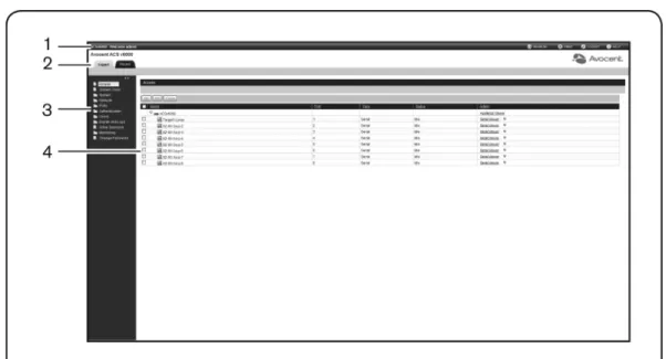
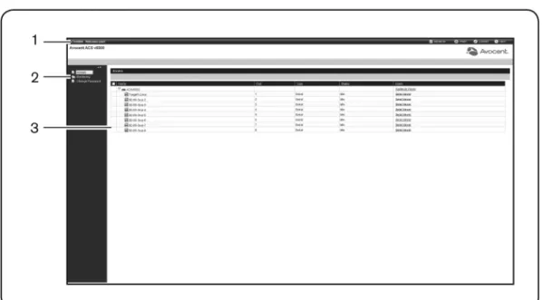
1. Open a web browser and enter the virtual console server IP address in the address field. 2. Log in as eitheradminwith the passwordavocentor asrootwith the passwordlinux. Figure 3.1 shows a typical web manager screen for an administrator and descriptions follow in Table 3.1.
Figure 3.1: Administrator Web Manager Screen
Number
Description
1 Top option bar. The name of the appliance and of the logged in user appear on the left side. Refresh, Print, Logout and Help buttons appear on the right. 2 Tab bar. Displays whether the admin is in Expert or Wizard mode.
3 Side Navigation Bar. Menu options for configuration, viewing of system information and access to devices. The options change based on user rights.
4 Content area. Contents change based on the options selected in the side navigation bar.
Table 3.1: Web Manager Screen Areas
Wizard Mode
The Wizard mode is designed to simplify the setup and configuration process by guiding an administrator through the configuration steps. An administrator can configure all ports in the
CAS Profile and set the Security Profile, Network, Users Settings and add licenses using the Wizard.
By default, the first time an administrator accesses the virtual console server through the Web Manager, the Wizard will be displayed. Subsequent log-ins will open in Expert mode, and once the virtual console server has been configured, Expert mode becomes the default mode. An administrator can toggle between Expert and Wizard modes by clicking the tab bar on the Web Manager administrator screen.
NOTE:The virtual console server has one serial port licensed by default. Click theLicensetab to configure the license before starting the Wizard configuration.
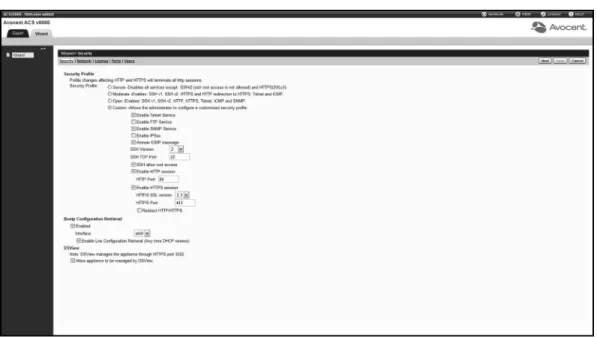
Figure 3.2 shows a typical screen when an administrator is in Wizard mode.
Figure 3.2: Wizard Screen
The following procedures describe how to configure the virtual console server from the Wizard. To configure security parameters and select a Security Profile:
1. Select theSecuritylink in the content area.
2. Select the desired Security Profile. If using a Custom Security Profile, click the checkboxes and enter values as needed to configure the services, SSH and HTTP and HTTPS options to conform with your site security policy.
1. Select theNetworklink in the content area.
2. Enter the Hostname, Primary DNS and Domain in the appropriate fields.
3. Select the IPv4 or IPv6 method for the ETH0 interface. If using Static, enter the Address, Mask and Gateway in the appropriate fields.
4. ClickNextto configure licenses or click theSecurity,License, PortsorUserslink to open the appropriate screen.
To configure licenses:
1. Select theLicenselink in the content area.
2. To add a license, click theAddbutton and enter the license in the License field.
-or-To delete a license, check the box next to the license you want to delete and click the
Deletebutton.
3. ClickNextto configure ports or click theSecurity,Network,PortsorUserslink to open the appropriate screen.
NOTE:Adding or deleting a license will save the license configuration and the configuration done in the other Wizard pages.
To configure Ports:
1. Select thePortslink in the content area. 2. Check the box(es) to enable all ports.
3. Use the appropriate drop-down menus to select the values for Protocol, Authentication Type and Data Buffering Status.
4. Select the Data Buffering Type. If using NFS, enter the NFS Server and NFS Path information in the appropriate fields.
5. ClickNextto configure users or click on theNetwork,Security, LicenseorUserslink to open the appropriate screen.
To configure users and change the default user passwords:
WARNING:For security reasons, it is recommended you change the default password for both root and admin users.
1. Select theUserslink in the content area.
2. Click a username (adminorroot) and enter the new password in the Password and Confirm Password fields.
-or-ClickAdd to add a user. Enter the new username and password in the appropriate fields.
3. (Optional) To force the user to change the default password, select theUser must change password at next login checkbox.
4. Assign the user to one or more groups.
5. (Optional) Configure account expiration and password expiration. 6. ClickNext.
7. Repeat steps 3-7 as needed to configure new user accounts and assign them to default groups.
NOTE:By default, all configured users can access all enabled ports. Additional configuration is needed if your site security policy requires you to restrict user access to ports.
8. ClickSave,then click Finish.
Expert Mode
The following tabs are available in the Side Navigation Bar of the web manager when an administrator is in Expert mode.
Access
ClickAccessto view all the devices connected to the virtual console server. To view and connect to devices using the web manager:
1. SelectAccessin the Side Navigation Bar. The content area displays the name of the virtual console server and a list of names or aliases for all installed and configured devices the user
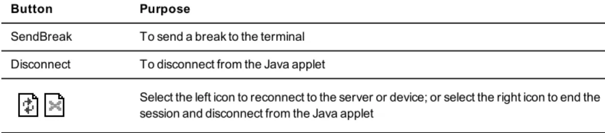
Button Purpose
SendBreak To send a break to the terminal Disconnect To disconnect from the Java applet
Select the left icon to reconnect to the server or device; or select the right icon to end the session and disconnect from the Java applet
Table 3.2: Java Applet Buttons for Connecting to the Virtual Console Server
System Tools
ClickSystem Toolsto display icons which can be clicked to reboot or shut down the virtual console server, upgrade the virtual console server’s software, save or restore its configuration or open a terminal session with the virtual console server.
NOTE:Use the web manager to shut down the virtual console server before turning it off.
System
ClickSystem to display information about the virtual console server and allow an administrator to configure the virtual console server’s system parameters. The following tabs are listed under System in the Side Navigation Bar.
Security profiles
Security Profiles determine which network services are enabled on the virtual console server. During initial configuration, the virtual console server administrator must configure security parameters to conform with the site security policy. The following security features can be configured either in the web manager, CLI or the DSView 3 software:
• Configure the session idle time-out • Enable or disable RPC
• Allow all users to access enabled ports or allow the configuration of group authorizations to restrict access
• Enable or disable BootP Configuration Retrieval and/or Live Configuration Retrieval • Select a Security Profile, which defines:
• Enabled services (FTP, ICMP, IPSec and Telnet) • SSH and HTTP/HTTPS access
The administrator can select either a preconfigured Security Profile or create a custom profile. All the services and the SSH and HTTP/HTTPS configuration options that are enabled and disabled for each Security Profile are shown in the Wizard - Security and the System - Security - Security Profile pages.
To configure the Security Profile:
1. SelectSystem - Security - Security Profile.
2. In the Idle Timeout field, enter the number of minutes before the virtual console server times out open sessions.
NOTE:This value applies to any user session to the appliance via HTTP, HTTPS, SSH or Telnet. The new idle time-out will be applied to new sessions only.
3. Under the Enabled Services section, enable or disable theRCPcheckbox.
4. Under the Serial Devices heading, enable or disable thePort access is controlled by authorizations assigned to user groupscheckbox.
5. Select the checkbox forCustom,Moderate,Open orSecureunder the Security Profile heading.
6. ClickSave.
You can also configure DSView 3 software security settings. When the virtual console server is managed by the DSView 3 software, the DSView 3 server will supply the certificate to the virtual console server. Under normal conditions, the DSView 3 software will manage the certificate to clear and replace it with a new certificate as needed. If communication with the DSView 3 software is lost, the DSView server will be unable to clear the certificate and the virtual console server cannot be used. Click theClear DSView Certificatebutton to configure the virtual console server in Trust All mode.
To configure DSView 3 software security settings: 1. SelectSystem - Security - DSView.
2. Click theAllow appliance to be managed by DSViewcheckbox and clickSave.
To set the time and date using NTP: 1. ClickSystem - Date And Time. 2. SelectEnable network time protocol.
3. Enter the NTP server site of your choice and clickSave. To set the time and date manually:
1. ClickSystem - Date And Time. 2. SelectSet manually.
3. Using the drop-down menus, select the required date and time and clickSave. To set the time zone using a predefined time zone:
1. ClickSystem - Date And Time - Time Zone. 2. SelectPredefined.
3. Select the required time zone from the drop-down menu and clickSave. To define custom time zone settings:
1. ClickSystem- Date And Time - Time Zone. 2. SelectDefine Time Zone.
3. Enter the Time Zone Name and Standard Time Acronym of your choice. 4. Enter the GMT Offset.
5. SelectEnable daylight savings timeif needed.
6. Select or enter the required values for daylight savings time settings and clickSave.
Help and Language
ClickSystem - Help And Languageand use the drop-down menu to select the virtual console server’s language. Enter the full URL of the online help, ending in /index.html, on the local
web server in the Online Help URL field. ClickSave. Online help
When the online help feature is configured for your virtual console server, clicking theHelp
button from any form on the web manager opens a new window and redirects its content to the configured path for the online help product documentation.
NOTE:Using the online help feature from the Avocent web site is not always possible due to firewall configurations, nor is it recommended. It is generally advisable for you to use the online help system provided with the product or download the online help .zip file and run it from a local server.
The system administrator can download the online help from Avocent. For more information on downloading the online help, contact Technical Support.
Once the online help file is obtained (in zip format), the files must be extracted and put in to a user-selected directory under the web server’s root directory. The web server must be publicly accessible.
NOTE:The default URL for online help is http://global.avocent.com/us/olh/acsv6000/v_2.3.0/en/index.html.
Information
ClickSystem-Informationto view the console server’s identity, versions and CPU information.
Usage
ClickSystem-Usageto view memory and disk usage.
VM Settings
ClickSystem-VM Settingsto configure the vCenter and to manage associations and licenses. VM Serial Ports
ClickSystem-VM Settings-VM Serial Portsto view all current associations between the virtual servers and the ACS v6000 virtual console server's serial ports. From this page, you can add, delete or resync associations. To delete an association, check the box next to the association(s) you want to delete and then clickDelete. To resync all associations, click Resync.
NOTE:Changes in the vSPC port configuration or in the ACS v6000 virtual console server's IP address may require the association to be resynced.
To add an association by Virtual Machine ID:
1. Click theAddbutton and selectVirtual Machine IDin the Search Available Machines By field.
6. Click theAddbutton to add the association. Repeat steps 2-3 for each association you want to add, then clickSave.
To add an association by Datacenter:
1. Click theAddbutton and selectDatacenter/Clusterin the Search Available Machines By field, then clickNext.
2. In the Select Datacenter field, select the data center. The Select Cluster(s) field shows all clusters in the selected data center.
3. ClickNextto see all virtual machines available in the selected data center.
-or-Select one or more cluster(s) to see all virtual machines available in the selected cluster(s). ClickNext.
4. In the Virtual Machine ID field, select the virtual server you want to associate. 5. In the Virtual Port field, select the virtual port you want to use in this association. 6. In the Serial Port field, select the serial port in the virtual console server to be associated
with the virtual machine/virtual port.
7. Click theAddbutton to add the association. Repeat steps 2-4 for each association you want to add, then clickSave.
vCenter
ClickSystem-VM Settings-vCenterto configure the vCenter that manages the virtual servers connected to the the ACS v6000 virtual console server.
To configure a vCenter:
1. Enter the IP address, username and password in the appropriate fields under the vCenter heading.
NOTE:Without the configuration of vCenter, the configuration of associations via the virtual console server and the power action of targets via the virtual console server will not be available. The password will be encrypted and stored in the appliance. The virtual console server will be registered in the vCenter as ACS v6000 and it will not show up in any list of available virtual machines for association.
2. Enter the vSPC port that is the TCP port the virtual console server will listen to for Telnet connections from the VMware ESX or ESXi server, then clickSave.
NOTE:Do not use a TCP port that conflicts with the TCP port alias of serial ports.
To power control targets using the web manager:
1. After you have configured a vCenter, selectAccessin the Side Navigation Bar. The content area displays the name of the virtual console server and a list of names or aliases for all installed and configured devices the user is authorized to access. The State column shows the current power state of the virtual machine.
2. If the user is authorized to power control the target, the power control operations (Power On, Power Off, Power Cycle and Suspend) are available in the Action column. Action buttons are available at the top of the table.
3. Select the target(s) and click the appropriate action button. The command will be sent to the vCenter to be performed.
NOTE:Power operations may take a long time to be performed. The user should be patient and refresh the page to check the state of the targets.
License
ClickSystem-VM Settings-Licenseto view license information for the ACS v6000 virtual console server. To add a license clickAdd, then enter the license number in the License field. To delete a license, check the box next to the license you want to delete, then clickDelete.
NOTE:A virtual console server supports up to 48 licensed serial ports. To license more than 48 serial ports, you must install another virtual console server and license the additional ports on that virtual console server. If you try to license more than 48 serial ports on a single virtual console server, the excess ports will not appear.
NOTE:The software comes with one virtual serial port open for evaluation purposes; it will be removed during the Add license process.
NOTE:Licenses that are duplicated will be detected and the total number of licensed serial ports will be reduced by the number provide by the duplicated license.
Network
ClickNetworkto view and configure the network options for Hostname, DNS, IPv6, IPv4 and IPv6 static routes, Hosts, Firewall, IPSec (VPN) and SNMP.
1. SelectNetwork - Devices. The Devices screen appears with a list of network interfaces and their status (enabled or disabled).
2. Click the name of the network device to configure. 3. Select one of the following IPv4 method options:
• SelectDHCPto have the IPv4 IP address set by the DHCP server. • SelectStaticto enter the IPv4 IP address and subnet mask manually. • SelectIPv4 address unconfiguredto disable IPv4.
4. Select one of the following IPv6 method options:
• SelectStatelessif the link is restricted to the local IP address. • SelectDHCPv6to have the IPv6 IP address set by the DHCP server. • SelectStaticto enter the IPv6 IP address and prefix length manually. • SelectIPv6 address unconfiguredto disable IPv6.
NOTE:The MAC Address for the device will be displayed after this option.
IPv4 and IPv6 static routes
To add static routes:1. SelectNetwork - IPv4 Static RoutesorIPv6 Static Routes.Any existing static routes are listed with their Destination IP/Mask, Gateway, Interface and Metric values shown. 2. ClickAdd.
3. SelectDefaultto configure the default route.
-or-SelectHost IP Or Networkto enter custom settings for Destination IP/Mask.
Enter the required Destination IP/Mask Bits with the syntax <destination IP>/<CIDR> in the Destination IP/Mask Bits field.
4. Enter the IP address of the gateway in the Gateway field.
5. Enter the number of hops to the destination in the Metric field, then clickSave.
Hosts
An administrator can configure a table of host names, IP addresses and host aliases for the local network.
To add a host:
1. SelectNetwork - Hosts. 2. ClickAdd to add a new host.
3. Enter the IP address, hostname and alias of the host you want to add, then clickSave. To edit a host:
1. SelectNetwork - Hosts.
2. Click on the IP address of the hostname you want to edit. 3. Enter a new hostname and alias, as applicable, then clickSave.
Firewall
Administrators can configure the virtual console server to act as a firewall. By default, three built-in chains accept all INPUT, FORWARD and OUTPUT packets. Select theAdd,Deleteor
Change Policybuttons to add a user chain, delete user added chains and to change the built-in chains policy. Default chains can have their policy changed (Change Policy) to accept or drop, but cannot be deleted. Clicking on theChain Nameallows you to configure rules for chains. Firewall configuration is available by clicking onNetwork - Firewall. Separate but identical configuration screens are available from either theIPv4 Filter TableorIPv6 Filter Tablemenu options.
Only the policy can be edited for a default chain; default chain policy options are ACCEPT and DROP.
When a chain is added, only a named entry for the chain is created. One or more rules must be configured for a chain after it is added.
Configuring the firewall
For each rule, an action (eitherACCEPT,DROP,RETURN,LOGorREJECT) must be selected from the Target pull-down menu. The selected action is performed on an IP packet that matches all the criteria specified in the rule.
Different fields are activated for each option in the Protocol pull-down menu.
IfNumericis selected from the Protocol menu, enter a Protocol Number in the text field. IfTCPis selected from the Protocol menu, a TCP Options Section is activated for entering source and destination ports and TCP flags.
IfUDPis selected from the Protocol menu, the UDP section is activated for entering source and destination ports.
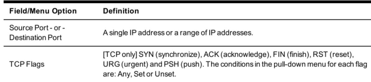
Field/Menu Option Definition
Source Port or
-Destination Port A single IP address or a range of IP addresses.
TCP Flags
[TCP only] SYN (synchronize), ACK (acknowledge), FIN (finish), RST (reset), URG (urgent) and PSH (push). The conditions in the pull-down menu for each flag are: Any, Set or Unset.
Table 3.3: Firewall Configuration - TCP and UDP Options Fields
IfICMPis selected from the Protocol menu, the ICMP Type pull-down menu is activated. If an administrator enters the Ethernet interface (eth0) in the input or output interface fields and selects an option (2nd and further packets,All packets and fragmentsorUnfragmented packets and 1st packets) from the Fragments pull-down menu, the target action is performed on packets from or to the specified interface if they meet the criteria in the selected Fragments menu option.
To add a chain:
1. SelectNetwork - Firewall.
2. Select eitherIPv4 Filter TableorIPv6 Filter Tableas needed. 3. ClickAdd.
4. Enter the name of the chain to be added. 5. ClickSave.
NOTE:Spaces are not allowed in the chain name.
6. Add one or more rules to complete the chain configuration. To change the policy for a default chain:
NOTE:User-defined chains cannot be edited. To rename a user-added chain, delete it and create a new one.
1. SelectNetwork - Firewall.
2. Select eitherIPv4 Filter TableorIPv6 Filter Tableas needed.
3. Select the checkbox next to the name of the chain you want to change (FORWARD,
INPUT,OUTPUT).
4. ClickChange Policyand selectAccept orDrop from the drop-down menu. 5. ClickSave.
To add a rule:
1. SelectNetwork - Firewall.
2. Select eitherIPv4 Filter TableorIPv6 Filter Tableas needed.
3. From the chain list, click the name of the chain to which you want to add a rule. 4. ClickAdd and configure the rule as needed, then clickSave.
To edit a rule:
1. SelectNetwork - Firewall.
2. Select eitherIPv4 Filter TableorIPv6 Filter Tableas needed.
3. From the chain list, click the name of the chain with the rule you want to edit. 4. Select the rule you want to edit and clickEdit.
5. Modify the rule as needed and clickSave.
IPSec(VPN)
Virtual Private Network (VPN) enables a secure communication between the virtual console server and a remote network by utilizing a gateway and creating a secured connection between the virtual console server and the gateway. The IPSec protocol is used to construct the secure tunnel and provides encryption and authentication services at the IP level of the protocol stack.
NOTE:IPSec(VPN) is not supported with IPv6.
WhenNetwork - IPSec(VPN)is selected, the IPSec(VPN) screen is displayed.
referred to as the local or left host. If left and right are not directly connected, then you must also specify a NextHop IP address.
The next hop for the remote or right host is the IP address of the router to which the remote host or gateway running IPSec sends packets when delivering them to the left host. The next hop for the left host is the IP address of the router to which the virtual console server sends packets to for delivery to the right host.
A Fully Qualified Domain Name should be indicated in the ID fields for both the Local (Left) host and the Remote (Right) host where the IPSec negotiation takes place.
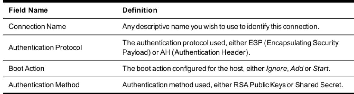
The following table describes the fields and options on theIPSec(VPN) - Addscreen. The information must match exactly on both ends for local and remote.
Field Name Definition
Connection Name Any descriptive name you wish to use to identify this connection.
Authentication Protocol The authentication protocol used, either ESP (Encapsulating Security Payload) or AH (Authentication Header).
Boot Action The boot action configured for the host, eitherIgnore,AddorStart. Authentication Method Authentication method used, either RSA Public Keys or Shared Secret.
Field Name Definition
Remote (Right) Side - and - Local (Left) Side
Enter the required address or text for each of the four fields for both Remote Side and Local Side: ID: This is the hostname that a local system and a remote system use for IPSec negotiation and authentication. It can be a fully qualified domain name preceded by @. For example,
[email protected]IP Address: The IP address of the host. NextHop: The router through which the virtual console server (on the left side) or the remote host (on the right side) sends packets to the host on the other side. SubNet: The netmask of the subnetwork where the host resides. Use CIDR notation. The IP number followed by a slash and the number of ‘one’ bits in the binary notation of the netmask. For example, 192.168.0.0/24 indicates an IP address where the first 24 bits are used as the network address. This is the same as 255.255.255.0.
RSA Key (IfRSA Keyis selected)
For IPSec(VPN) authentication, you need to generate a public key for the virtual console server and find out the key used on the remote gateway. Copy and paste for copying the RSA key from another source is supported. Pre-Shared Secret (If Secret is
selected) Pre-shared password between left and right users.
SNMP Configuration
An administrator can configure SNMP, which is needed if notifications are to be sent to an SNMP management application.
NOTE:The Avocent ACS v6000 Enterprise MIB text file is available in the appliance at: /usr/local/mibs/ACSv6000-MIB.asn. The Avocent ACS v6000 Enterprise TRAP MIB text file is available in the appliance at:
/usr/local/mibs/ACSv6000-TRAP-MIB.asn. Both files are also available at www.avocent.com.
To configure SNMP: 1. ClickNetwork - SNMP.
2. Click theSystembutton and enter the SysContact information (email address of the virtual console server’s administrator, for example,[email protected]).
3. ClickAdd to add a new community or v3 user.
4. Enter the community name for SNMP v1/v2 or the user name for SNMP v3 in the Name field and enter the OID.
5. Select the desired permission from the pull-down menu. Choices areRead and Writeor
Read Only.
Authentication Type (MD5orSHA), enter the authentication passphrase or password, enter the privacy passphrase for DES and select the Minimum Authentication Level (NoAuthNoPriv,AuthNoPriv,AuthPriv).
7. ClickSave.
Ports
An administrator can enable and configure serial ports and the CAS Profile from the Ports tab in the Side Navigation Bar.
Serial ports
On the Serial Ports table, you can clone the port, reset to factory defaults and enable/disable ports.
To enable or disable one or more serial ports: 1. SelectPorts - Serial Ports.
2. Click the checkbox for each port you want to enable or disable. 3. Click theEnabledorDisabledbutton.
To configure or edit one or more serial ports with the CAS Profile: 1. SelectPorts - Serial Ports.
2. Click the checkbox for each port you want to configure. 3. Click theSet CASbutton.
a. Enter the port name (when only one port was selected) or the port name prefix (when more than one port were selected). The port name will be <port name prefix>-p-<port number>.
b. Check the box to enable auto discovery. In this case, the port name will be used when auto discovery fails to discover the server name.
d. Enter the text session and power session hotkeys in the appropriate fields. e. Enter the TCP port alias in the appropriate field.
f. Enter the IPv4 or IPv6 alias and its interface in the appropriate field.
g. To allow a session only if DCD is on and to enable auto answer, check the appropriate boxes.
h. Use the drop-down menu to select the DTR mode and enter the DTR off interval. i. Use the drop-down menus to enable or disable line feed suppression and NULL after
CR suppression.
j. Enter the transmission interval, break sequence and break interval in the appropriate fields.
k. Use the drop-down menus to enable or disable log in/out multisession notification and informational message notification.
4. ClickNextor click theData Bufferinglink and use the drop-down menus to enable and configure data buffering.
5. ClickNextor click theAlertslink.
a. ClickEnable Alertsto enable detection of alerts.
b. ClickAdd to add an alert string. Enter the string in the Alerts String field and click
Nextto return to the Alerts screen.
c. Check the box next to an existing alert and clickDeleteto delete the string. d. ClickDelete Anyto delete all strings whether selected or not.
NOTE:ClickingDelete Anywill delete all alert strings. Selecting all the alert strings and clickingDeleteis not the same functon as it will not delete alert strings not shown in the table.
6. ClickSave.
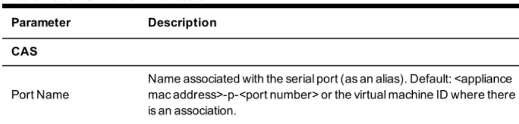
Parameter Description
CAS
Port Name
Name associated with the serial port (as an alias). Default: <appliance mac address>-p-<port number> or the virtual machine ID where there is an association.
Table 3.5: CAS Profile Parameters
Protocol
can use SSH and/or Telnet to connect to the console of a connected device simultaneously. Raw - Authorized users can make a Raw Socket connection to the console of a connected device. Default: SSH/Telnet.
Authentication Type Authentication type that will be used to authenticate the user during target session. Default: Local.
Text Session Hot Key
Hotkey to suspend the target session and go to the CLI prompt. Not available for Raw. Default:Ctrl-Z.NOTE:The default escape character for ts_menu isCtrl-X.
Power Session Hot Key
Hotkey to suspend the target session and display Power Management Menu to control the power state of the target. Not available for Raw. Default:Ctrl-P.NOTE:The default escape character for ts_menu is
Ctrl-X.
TCP Port Alias
For a Telnet/Raw session: TCP port to connect directly to a serial port. For SSH session: Alias of the port similar to ttySxx. Default: 70XX, where XX is the serial port number.
Port IPv4/IPv6 Alias IPv4/IPv6 address used to connect directly to a serial port. Default: not configured (empty).
Port IPv4/IPv6 Alias
Interface Interface (ETH0) associated with the IPv4/IPv6 alias. Allow Session Only if
DCD is On
When the DCD is OFF, the appliance will deny access for this serial port. Default: Disabled (allow access if DCD is OFF).
Enable Auto Answer
When the input data matches one input string configured in Auto Answer, the output string will be transmitted to the serial port. Default: Disabled.
DTR Mode
DTR Mode can be set to the following: Always On. Normal - the DTR status will depend on the existence of a CAS session. Off Interval -when the a CAS session is closed, the DTR will stay down during this interval. Default: Normal.
Parameter Description
DTR Off Interval Interval in seconds used by DTR Mode Off Interval in milliseconds. Default: 100.
Line Feed Suppression Enables the suppression of the LF character after the CR character. Default: Disabled.
Null After CR Suppression
Enables the suppression of the NULL character after the CR character. Default: Disabled.
Transmission Interval The interval the port waits to send data to a remote client in milliseconds. Default: 20.
Break Sequence Sequence used to send a break signal to the serial port. Not available for Raw. Default: ~break.
Break Interval Interval for the break signal in milliseconds. Not available for Raw. Default: 500.
Log In/Out Multi Session Notification
Enables the notification to multi-session users when a new user logs in or a user logs out. Not available for Raw. Default: Disabled.
Informational Message Notification
Displays an information message when a target session is opened. Not available for Raw. Default: Enabled.
Data Buffering
Status Enables or disables data buffering. Default: Disabled.
Type
Displays the type of data buffering: Local - stores the data buffering file in the local file system. NFS - stores the data buffering file in the NFS server. Syslog - sends the data to the syslog server. DSView - sends the data to the DSView 3 software. Default: Local.
Time Stamp When enabled, adds the time stamp to the data buffering line for a Local or NFS database. Default: Disabled.
Log-in/out Message Includes special notification for logins and logouts in data buffering. Default: Disabled.
Serial Session Logging Enabled - stores data at all times. Disabled - stores data when a CAS session is not opened. Default: Enabled.
Alerts
Status A special event notification will be generated when input data matches one of the alert strings. Default: Disabled.
Alert Strings Strings used to generate event notifications. Default: Empty.
TCP Port Alias, IPv4 Port Alias and IPv6 Port Alias.
To reset one or more serial ports to their factory configuration: 1. SelectPorts - Serial Ports.
2. Click the checkbox for one or more serial ports you want to reset to their factory configuration, then click theReset To Factorybutton.
NOTE:Serial ports are set to the CAS Profile and disabled in the factory configuration.
CAS Profile
An administrator can configure settings for auto discovery and for auto answer features. Auto discovery
The auto discovery feature will discover the target name of the server connected to the serial port. This name will be used as the alias of the serial port.
When auto discovery is active for a certain serial device, upon target connection (DCD ON event), the appliance will send probe strings and start analyzing target device answers using regular expressions. There will be predefined probe and match strings as well as customer-defined ones.
For each probe string sent, all regular expressions defined by the match strings will be tested. After the last cycle, the sequence restarts. This procedure will run for a certain period (given by the auto discovery time-out parameter) or until the target is successfully detected. If auto discovery fails, the target name will be reset to the configured target name or to the corresponding unique default target name.
NOTE:The configured target name will be used only after the auto discovery process fails.
NOTE:The auto discovery process starts when there is variation in the DCD signal from OFF to ON
(disconnect/connect the target's cable, turn off/on the target) and when the configuration of the serial port goes from disabled to enabled and there is a target connected in the port.
The match strings are regular expressions where “%H” is a placeholder for the target name you want to detect, such as:
“ \\(.*\\)(%H)\\(.*\\)” or just “xxx%Hyyy”. The first one will extract target name from things such as:
nanana(myTarget): à results: myTarget jhdsgjhas(tg2)kjafja à results: tg2 But would match for:
hsagdfjhagfxxxTARGETyyyyyy à resulting: TARGET
To configure the strings for probe/match used by auto discovery:
Perform this procedure to change the default settings or the probe or match strings used in auto discovery.
1. SelectPorts - CAS Profile - Auto Discovery. The Settings, Probe Strings and Match Strings options appear in the Side Navigation Bar.
2. To change the default auto discovery time-out or probe time-out, perform the following steps.
a. SelectSettings.
b. Enter a new value in the Auto Discovery Timeout and Probe Timeout fields. c. ClickSave.
3. To add a new probe or match string or delete an existing string, perform the following steps.
a. SelectProbe StringsorMatch Strings.
b. To add a string, clickAdd, enter a new string in the New Probe String or New Match String field and clickSave.
c. To delete a string, select the checkbox for the string and clickDelete. 4. ClickSave.
To configure the input/output strings used by auto answer: 1. SelectPorts - CAS Profile - Auto Answer.
2. To add an auto answer input and output string, clickAdd. Enter a new string in the Input String or Output String fields and clickSave.
the pool are taken, the connection to the pool is denied.
NOTE:All ports in the pool must share the same CAS protocol. The protocol is validated during the connection to the serial port. If the protocol does not match, the connection will be denied.
To configure a pool of CAS ports: 1. ClickPorts - Pool of CAS Ports. 2. To create a pool, click theAddbutton.
or
-To edit an existing pool, click the name of the pool you want to edit. or
-To delete a pool, check the box next to the pool you want to delete and click the
Deletebutton.
3. Enter the parameters for the pool in the appropriate fields.
4. In the left side of the Pool Members field, select the ports to be added to the pool and click
Add. or
-In the right side of the Pool Members field, select the ports to be removed from the pool and clickRemove.
5. ClickSave.
NOTE:A serial port can only belong to one pool at a time, but a user can create an empty pool and add ports to it later.
Parameter Description
Pool Name The name of the pool. The pool name is mandatory and should follow hostname guidelines, not exceed 64 characters and start with a letter.
TCP Port
Alias The TCP Port Alias where the pool responds. This parameter is optional. Pool IPv4
Alias The IPv4 address used by the pool. This parameter is optional. Pool IPv4
Alias Interface
The interface (Eth0) used by the IPv4 Alias.
Pool IPv6
Alias The IPv6 address used by the pool. This parameter is optional. Pool IPv6
Alias Interface
The interface (Eth0) used by the IPv6 Alias.
Table 3.6: Pool of CAS Ports Parameters
Authentication
Authentication can be performed locally, with OTP, or on a remote Kerberos, LDAP, NIS, Radius or TACACS+ authentication server. If the virtual console server is managed by a DSView 3 server, DSView authentication is also supported. The virtual console server also supports remote group authorizations for LDAP, Radius and TACACS+ authentication methods.
Fallback mechanisms of the following types are available:
Local authentication can be tried first, followed by remote, if the local authentication fails (Local/Remote_Method).
-or-Remote authentication may be tried first, followed by local (-or-Remote_Method/Local).
-or-Local authentication may be tried only if a remote authentication server is down (Remote_ Method_Down_Local).
An administrator can configure authentication using the CLI utility or the web manager. The default authentication method for the virtual console server and the serial ports is Local. Any Chapter 3: Accessing a Virtual Console Server via the Web Manager 35
When Single Sign-on Authentication is disabled, the virtual console server uses the individual port configurations. Users must use their password each time they access an individual port. If enabled, Single Sign-on Authentication will use the authentication server you choose from the pull-down menu for all ports and no further authentication will be needed when accessing the port after that.
NOTE:Selectingunconfiguredfrom the pull-down menu will allow the ports to continue to use individual
authentication servers, and will require your password the first time you access any port. After that, the port will not require password authentication if Single Sign-on Authentication is enabled.
To set authentication for the console server: 1. ClickAuthentication - Appliance Authentication.
2. Select the desired authentication server from the Authentication Type drop-down menu. 3. SelectEnable single sign-onto enable single sign-on authentication, and select the desired
authentication server from the Authentication Type drop-down menu. 4. ClickSave.
Authentication servers
When using an authentication server, you must configure its IP address and in most cases other parameters before it can be used. The following authentication servers require configuration: RADIUS, TACACS+, LDAP(S)|AD, Kerberos, NIS and DSView 3 servers.
To configure a RADIUS authentication server:
1. SelectAuthentication - Authentication Servers - RADIUS.
2. Enter the IP addresses of the First Authentication Server and First Accounting Server. 3. If used, enter the IP addresses for the Second Authentication Server and Second Accounting
4. Enter your secret word or passphrase in the Secret field (applies to both first and second authentication and accounting servers), then re-enter the secret word or passphrase in the Confirm Secret field.
5. Enter the desired number of seconds for server time-out in the Timeout field. 6. Enter the desired number of retries in the Retries field.
7. If you select theEnable Service-Type attribute to specify the authorization group
checkbox, enter the authorization group name for each of the following Service Types: Login, Framed, Callback Login, Callback Framed, Outbound and Administrative. 8. ClickSave.
To configure a TACACS+ authentication server:
1. SelectAuthentication - Authentication Servers - TACACS+.
2. Enter the IP addresses for the First Authentication Server and First Accounting Server. 3. If used, enter the IP addresses of the Second Authentication Server and Second Accounting
Server.
4. Select the desired service (PPP or raccess) from the Service drop-down menu.
5. Enter your secret word or passphrase in the Secret field (applies to both first and second authentication and accounting servers), then re-enter the secret word or passphrase in the Confirm Secret field.
6. Enter the desired number of seconds for server time-out in the Timeout field. 7. Enter the desired number of retries in the Retries field.
8. If you select theEnable User-Level attribute to specify the authorization groupcheckbox, enter the authorization group name for up to 15 User-Levels.
9. ClickSave.
To configure an LDAP(S)|AD authentication server:
1. SelectAuthentication - Authentication Servers - LDAP(S)|AD.
2. Enter the IP address of the server. 3. Enter the Base.
4. At the Secure drop-down menu, selectOff,OnorStart_TLS. 5. Enter the Database User Name.
2. Enter the IP address (Realm) of the server.
3. Enter the Realm Domain Name (example:avocent.com). 4. Enter the Domain Name (example:avocent.com). 5. ClickSave.
To configure an NIS authentication server:
1. SelectAuthentication - Authentication Servers - NIS.
2. Enter the NIS Domain Name of the server (example:corp.avocent.com). 3. Enter the NIS Server Address orbroadcast(default is broadcast). 4. ClickSave.
To configure a DSView authentication server:
1. SelectAuthentication - Authentication Servers - DSView.
2. Enter IP Address 1 - 4 for the DSView servers in the relevant fields. 3. ClickSave.
Users Accounts and User Groups
Access to ports can be optionally restricted, based on authorizations that an administrator can assign to custom user groups. The virtual console server has two default users (admin and root) and four pre-defined user groups: admin, appliance-admin, shell-login-profile and user.
A user account must be defined for each user on the virtual console server or on an authentication server. The admin and root users have accounts by default, and either
administrator can add and configure other user accounts. Each local user account is assigned to one or more of the user groups.
Local accounts
The admin and root are equivalent users but named differently to address users familiar with either Avocent or Cyclades™ appliances. Regular users can be granted permissions by administrators at any time. The virtual console server has three user account types:
• admin: Performs the initial network configuration. The factory default password for admin isavocent. The admin user is a member of the admin group and can configure the virtual console server and ports as well as user and group authorizations.
• root: Has the same permissions as the admin user. The factory default password for root is
linux. In the virtual console server, the root user is a member of the admin group and shell-login-profile groups. When a root user logs in via SSH or telnet, the session is pre-defined by the login profile to go directly to shell. The login profile can be customized so that it does not go directly to shell.
• Administrator-added regular users: Have limited access to the web manager features based on the group(s) to which they are assigned. Users can change their own passwords. By default, all users have access to all enabled ports.
To add new users:
1. ClickUsers - Local Accounts - User Names. The User Names screen is displayed with a list of all users.
2. ClickAdd.The Local User Information screen is displayed.
3. Enter the new username and enter a password, then confirm the password. 4. Select or deselectUser must change password at the next logincheckbox.
5. If you wish to add the user to an available user group, select the user group name in the box on the left and clickAdd(user is the default group). You can remove a user group from the box at right by selecting it and clickingRemove.
6. Enter the desired parameters for Password Expiration.
• Min Days: Enter the minimum number of days allowed between password changes. Password changes attempted sooner will be rejected. If not specified, -1 is the default which disables the restriction.
• Max Days: Enter the maximum number of days a password is valid. After this period, a password change will be forced. If not specified, -1 is the default which disables the restriction.
1. ClickUsers - Local Accounts - Password Rules.
2. If password complexity is desired (recommended), make sureCheck Password Complexity
is selected.
3. If password complexity is enabled, enter the desired values for password complexity. 4. Enter the desired values for Default Expiration.
5. ClickSave.
User groups
User groups are given access and authorizations either by default or as assigned by an administrator. Administrators can alter the permissions and access rights of users belonging to the appliance-admin or user groups or create additional groups with custom permissions and access rights. Administrators can add, delete or modify permissions and access rights for users from any group at any time.
If an administrator configures the virtual console server to restrict user access to ports, the administrator can assign users to groups that are authorized for port access. The administrator can also authorize groups for data buffer management.
This document and the software refer to users whose accounts are configured on remote authentication servers as remote users. Remote users do not need local accounts.
Radius, TACACS+ and LDAP authentication services allow group configuration. If a remote user is configured as a member of a remote group, the authentication server provides the group name to the virtual console server when it authenticates the user. A local group by the same name must also be configured on the virtual console server. If an authentication server authenticates a remote user but does not return a group, then the remote user is, by default, assigned to the user group.
admin group
Members of the admin group have full administrative privileges that cannot be changed, the same access and configuration authorizations as the default admin user. Administrators can
configure ports and add users.
NOTE:The only configuration allowed for the admin group is adding or deleting members.
To view admin Appliance Access Rights:
1. ClickUsers - Authorization - Groups. The Group Names screen is displayed, showing the three default user groups along with any groups that have been created.
2. Click onadminunder the Group Name heading. The content area will display the Members screen listing all members belonging to the admin group (default members are admin and root users).
NOTE:When any Group Name is selected, both the content area and side navigation bar change. The side navigation bar will display specific menu options for Members and Access Rights (which include Serial and Appliance rights).
3. In the side navigation bar, clickAccess Rights - Serial to access the screens displaying the fixed access rights and permissions for members of the admin group pertaining to serial ports.
NOTE:The Serial screen is read-only and cannot be changed.
4. In the Side Navigation Bar, click onAccess Rights - Appliance. The Appliance Access Rights screen appears and lists all access rights available to a member belonging to the admin group. All appliance access rights are shown enabled (checked). Available appliance access rights are:
• View Appliance Information
• Disconnect Sessions and Reboot Appliance • Appliance Flash Upgrade and Reboot Appliance • Configure Appliance Settings
• Configure User Accounts • Backup/Restore Configuration • Shell Access
• Transfer Files
NOTE:The Appliance Access Rights screen for the admin and appliance-admin user groups is read-only and cannot be changed. Unchecking any box and clickingSavewill result in an error message. The console server will maintain all rights selected.
administrator but have no access rights for the virtual console server. Administrators can add appliance access rights and permissions, or can add users to custom user groups to add permissions and access rights as needed. By default, all selections on the Appliance Access Rights screen will be disabled.
NOTE:The Appliance Access Rights screen for the user group can be changed at any time by an administrator. This will change the access rights for all members of the console server’s user group.
shell-login-profile
Members of the shell-login-profile group have access to the shell after logging in. By default, the root user belongs to this group. This is not a protected group and can be deleted.
Managing user groups
Administrators and members of the admin group can create custom user groups that contain any users. Permissions and access for custom user groups will be determined by the top-level user group permissions.
To create a custom user group:
1. ClickUsers - Authorization - Groups. The Groups screen is displayed and contains a list of the three default user groups and any additional custom user groups that have been created. 2. ClickAdd in the content area.
3. Enter the name of the new user group you are creating. 4. ClickSave.
To add members to a user group: 1. ClickUsers - Authorization - Groups.
2. Click the user group name.
3. ClickAdd. The Members Assignment screen is displayed showing a list of available users in the left box and an empty box on the right.
4. Move users from the Available Users box on the left to the box on the right by double-clicking on the username, or by selecting the name and double-clicking theAddbutton. You can remove any names from the box on the right by double-clicking on the name or by selecting the name and clicking theRemovebutton.
5. If you want to add remote users to the new user group (these must be valid names in your remote authentication server), add them in the New Remote Users field.
6. ClickSave.
To remove members from a user group: 1. ClickUsers - Authorization - Groups. 2. Click the user group name.
3. Check the box(es) of the member(s) you want to remove. ClickDeleteto delete the selected members.
To configure a login profile for a user group: 1. ClickUsers - Authorization - Groups.
2. Click on the name of the group whose login profile you want to set. In the Side Navigation Bar, clickLogin Profile.
3. Check theEnable Log-In Profilebox.
4. Clickts_menu to use the ts_menu application when a member of the selected user group opens a session in the console server. Enter the ts-menu options in the Options field.
-or-ClickCLIto use CLI when opening a session. Enter the CLI command in the CLI cmd field and check the box if you want to exit after executing the command.
5. ClickSave.
NOTE:If the user belongs to multiple groups, the login profile used will be the first enabled login profile based on alphabetical order of the group.
Command Description
-p Displays TCP port
-i Displays local IPv4 assigned to the serial port
Table 3.7: ts_menu Options
-ro Read-Only mode
<portname> Connect directly to a serial port
-t Idle time-out in seconds to choose the target
To add access to serial ports for a user group: 1. ClickUsers - Authorization - Groups.
2. Click the new user group name.
3. In the Side Navigation Bar, clickAccess Rights. 4. In the content area, clickAdd.
5. Move serial target devices from the Available Target box on the left to the box on the right by double-clicking on the serial target name, or by selecting the target and clicking the
Addbutton. You can remove any targets from the box on the right by double-clicking on the target or by selecting the target and clicking theRemovebutton.
6. Select the desired access rights.
7. ClickSave. The Serial screen will appear and show the serial target devices you have authorized for use by the user group with configured permission(s).
8. Edit the access rights by selecting the checkbox next to one or more of the target names in the list as needed and clickEdit. The Target Access Rights screen is displayed with the access rights. Select the desired access rights and clickSave.
To assign appliance access rights for custom user groups: 1. ClickUsers - Authorization - Groups.
2. Click the new user group name.
3. In the Side Navigation Bar, clickAccess Rights - Appliance.