Proceedings of the
Second International Workshop on
Bidirectional Transformations
(BX 2013)
Understanding bidirectional transformations with TGGs and JTL
Alessio Bucaioni, Romina Eramo
20 pages
Guest Editors: Perdita Stevens, James F. Terwilliger
Managing Editors: Tiziana Margaria, Julia Padberg, Gabriele Taentzer
Understanding bidirectional transformations with TGGs and JTL
Alessio Bucaioni1, Romina Eramo1
1name.surname@univaq.it
Dipartimento di Ingegneria e Scienze dell’Informazione e Matematica Universit`a degli Studi dell’Aquila, Italy
Abstract: In Model-Driven Engineering bidirectional model transformations emer-ged as an important ingredient to cope with scenarios such as change propagation, synchronization and to keep consistent system views whenever changes occurring on some view have to be propagated over the others. However, bidirectional map-pings open a number of intricate issues that have been only partially solved by re-search.
This paper identifies a set of features characterizing bidirectional transformations and validates them against two existing approaches. In particular, a scenario based on the UML2RDBMS transformation and consisting of two different configurations is implemented by means of two different approaches, such as Triple Graph Gram-mars and the Janus Transformation Language, for understanding bidirectional trans-formations with respect to the elicited features.
Keywords:TGGs, JTL, bidirectional transformations, MDE
1
Introduction
In Model-Driven Engineering (MDE) [Sch06] model transformations are considered as the gluing mechanism between the different abstraction layers and viewpoints by which a system is described [B´ez05, SK03]. Given the variety of scenarios in which they can be employed, each transformation problem can demand for different characteristics making the expectation of a single approach suitable for all contexts not realistic.
The contribution of this work is: (i) to identify a set of pragmatic features characterizing bidi-rectional model transformations and (ii) to validate them against two bidibidi-rectional approaches, such as the Triple Graph Grammars (TGGs) [Sch95], a bidirectional approaches based on graph grammars and the Janus Transformation Language (JTL) [CDEP11], a constraint-based bidirec-tional language.
The UML2RDBMS transformation scenario consisting of two different configurations is im-plemented by means of the selected approaches for understanding the practicality of bidirectional transformations with respect to the elicited features. At the same time an evaluation of the imple-mentations is provided highlighting differences and similarity between the approaches and giving a cue to identify their possible applications. We take into account a different version as the trans-formation is proposed in the literature, i.e., with the non isomorphic source (UML) and target (RDBMS) modeling languages. In order to apply the approaches to specific contexts concerning bidirectionality and change propagation, we implement the transformation by means of selected tools: in particular, we consider the EMorF and the eMoflon tools (both implementing TGGs) and the JTL framework. On the one hand, TGGs are a formally founded bidirectional language relying on multiple implementations, while JTL is a promising approach actively researched. On the other hand, they both consider intrinsic characteristics affecting bidirectionality.
The structure of the paper is as follows: Section2presents theUML2RDBMSscenario, while Section 3 introduces our set of features for bidirectional approaches. Section4 describes the TGGs and JTL approaches and shows how the transformations are specified, while Section5 execute them on the considered transformation and discusses the selected features of the consid-ered bidirectional approaches. Furthermore, Section6provides an overview of related works in the area. Finally, Section7draws the conclusions and presents future works.
2
Scenario
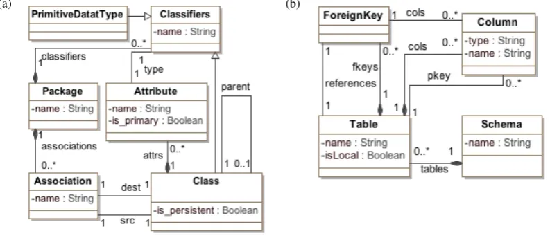
Bidirectional model transformations brings some not obvious issues mainly addressable to the non-injectivity and the non-totality of transformations as well as its own expressivity [HLR08]. To better illustrate such difficulties, hereafter we will consider a non-bijective class diagram to relational data base (UML2RDBMS) benchmark scenario [CFH+09,HLR08]. A simplified ver-sion of the UML and RDBMS metamodels are depicted in Figure1aand Figure1b, respectively. Only persistent classes are mapped to correspondent tables and their attributes to columns in the tables, including inherited attributes. In order to preserve all the information of the source dia-gram attributes of non-persistent classes have to be distributed over those tables stemming from persistent classes which access non-persistent ones.
2.1 Scenario configuration 1
Dealing with bidirectional transformations the invertibility of the function may be frustrating when the transformation is not bijective, which causes ambiguities when trying to map back corresponding target.
(a) (b)
Figure 1: Simplified UML (a) and RDBMS (b) metamodels
(a)
Person
name {is_primary}
Worker
working_address department
Employer {persistent} University PK name working_address University Employer department PK name working_address Professor department number_of_publications number_of_publications Professor {persistent} (b) Person
name {is_primary}
Worker working_address department Employer {persistent} University PK name working_address University Employer department PK name working_address Professor department number_of_publications number_of_publications Professor {persistent}
Figure 2: The UML model (a) and the correspondent RDBMS model (b)
In order to illustrate the difficulties which may occur, Figure2ashows a UML model. In par-ticular, the packageuniversityis composed of an inheritance hierarchy of classes. The persis-tent classprofessor, with attributenumber of publications, inherits from the persistent classemployer, with attribute department. The parent class workeris not persistent and contains the attributeworking address. Finally, the top parent non-persistent classperson
Applying theUML2RDBMS transformation to the class diagrams depicted in Figure2a, the schema in Figure2bis obtained. In particular, the inheritance hierarchy of non-persistent classes
personandworkerand persistent classemployeris flattened as a single tableemployerthat has columns for all the fields of the various classes. In general, attributes of the parent classes induce the corresponding columns in both the parent and child classes, then the tableprofessor
inherits all the attributes of the tableemployer. It gives rise to non-injective mappings.
Furthermore, in order to obtain the original source model from the target, the transformation should be able to preserve all the information of the UML model: i.e., non-persistent classes have to be generated again and attributes have to be restored in the original classes.
2.2 Scenario configuration 2
It is common that manual changes might be performed by designers on the generated models in order to resolve unforeseen requirements or limited expressiveness of the involved metamodels. For example, let us suppose that the generated model is manually modified as depicted in Figure3a. The first change involves a new column emailwhich has been added in the table
employer. This gives place to an interesting situation since such modifications can be reflected to the source model in Figure2a in three alternative ways: the attribute (corresponding to the manually added column) can be associated with the class employer or with each of parent classesworkerandperson, as in Figure3b. Consequently, more than one source model cor-rectly propagating the changes exist.
(a)
(b)
Figure 3: The modified RDBMS model (a) and the correspondent UML model (b)
has to be considered as shown in the new version of the RDBMS model in Figure3a. Because of the limited expressive power of the considered UML metamodel which does not support this annotation, such a revision does not have counterparts in the UML model in Figure3b.
3
Evaluation features
In this section we identify and describe a set of pragmatic features which we use to characterize the considered bidirectional model transformation approaches. The relevance to address bidi-rectional requirements has been acknowledged in the literature. In particular, by relying on the classification of model transformation approaches in [CH06], the definitions given in [HLR08] and the requirements and issues provided in [Ste09], we have selected a number of features, which are considered relevant for evaluating bidirectional approaches, preserving the opportu-nity to extend this set. In this work we focus mainly only on those features which are differently supported by the considered approaches.
3.1 Reverse
There are two main approaches for realizing bidirectional transformations: (i) by programming forward and backward transformations in any convenient unidirectional language, i.e., the back-ward transformation is given by user (we refer this case withgiven) or (ii) by using a bidirec-tional transformation language where each program describes both a forward and a backward transformation simultaneously (we refer this case with computed). A major advantage of the latter approach is that the consistency of the transformations can be guaranteed by construction. Contrariwise, an approach requiring the reverse transformation to be given by the user is cum-bersome and error-prone; in fact, the designer needs to manually ensure the consistency. The user has to guarantee also that the given reverse behaves like the mathematical inversion, i.e., it has to be guaranteed that f= f◦f−1◦f. If this property cannot be guaranteed, synchronization possibilities are reduced [HLR08].
3.2 Non-injective source/target relationship
The difficulty faced with bidirectional transformation is the often neglected fact that transforma-tions arenon-injectivein general.
To deal with this kind of situations there are at least two kinds of techniques. In particular, additional constraints can be added during the implementation of the transformation in order to avoid ambiguities. In other words, the mappings are made injective, in the sense that there can be only one way (encoded in the transformation code) to restore the consistency relation (programmatic solution). Alternatively, depending on the adopted tool, the transformation is able to generate all the feasible solutions according to the consistency relation embodied in the specified transformation (multiple solutions).
3.3 Partial domain coverage
Transformations in general arepartial, i.e. there are concepts in the source model that do not have a correspondence in the target model and vice-versa. Considering a transformation as a function, the partiality correspond to anot surjectivefunction (i.e., the image does not fill the whole co-domain of the function). By running the transformation in the backward direction, elements which do not have a counterpart may be lost (e.g., see the non-persistent classes in Figure2, and the added propertyisLocalin Figure 3). A bidirectional approach can be able to deal with a partial coverage of the transformation domains in two different way: by modify-ing the transformation with mappmodify-ings involvmodify-ing the neglected elements (forced mapping) or by implementing a dedicated supportto maintain and re-generate elements which are outside the transformation domain.
3.4 Tracing
Some of the difficulties arising from the forward and backward executions of transformations can be addressed by means of a dedicated management oftracing information[PDK+11] which collect different aspects of transformation executions.
In particular,trace linksbetween source and target model elements may be created and main-tained to contribute to the resolution of some ambiguities (for example, when restoring back the attributes in the original parent classes in Figure2). Furthermore, links between source and target elements should also consider elements discarded by the mapping for recording the information lost in the current execution of the transformation, which need to be stored and regenerated during the backward transformation (for example, the added propertyisLocalin Figure3).
The relevance of these features emerges in those applications demanding the preservation of a coherent description of the whole system, when asynchronous changes occur on source or target model and need to be propagated in the opposite direction (e.g., consistency management, synchronization, change propagation, round-trip engineering).
de-velopers may restrict transformations using programmatic solutions for efficiency reasons.
3.5 Incrementality
Incrementality refers to the ability to update existing target models based on changes in the source models, and vice versa [CH06]. In particular, incremental transformations synchronize two models by propagating modifications such that information not covered by the transforma-tion can be preserved and the computatransforma-tional effort can be minimized. In contrast, a classical batch transformation synchronizes two models taking a source model as input and computes the resulting target model from scratch, and vice versa [GW09].
Incrementality is used in change propagation scenario in order to update existing target models based on changes in the source models. A subsequent execution with the same source models as in the previous execution has to detect that the needed target elements already exist. This detection can be achieved, for example, by using traceability links. When any of the source models are modified and the transformation is executed again, the necessary changes to the target are determined and applied. At the same time, the target elements may be preserved. In general, incremental transformations are able to avoid information loss ( for example, elements discarded by the mapping as depicted in the previous Section).
Incrementality is an important feature in model transformation that deserves a more extensive discussion. However, for the purposes of this work, technical details will not be processed and incrementality is discussed focusing on the benefits gained with regard to the considered issues .
In the following sections, we present how the considered scenario is specified and executed by means of TGGs and JTL and discuss the evaluation of the approaches using the features defined in this section.
4
Specifying the transformation with TGGs and JTL
This section introduces the TGGs and the JTL approaches and how theUML2RDBMS transfor-mation is specified by means of them1. The TGGs transformation specification is given with the EMorF notation, which can be considered as a general abstract syntax for the approach. Whereas, the JTL transformation is specified by means of its own textual syntax.
4.1 TGGs
TGGs as introduced by Sch¨urr [Sch95,KS06] belong to the class of graph transformations, and it is considered as a natural framework for specifying bidirectional model transformations.
Formally, atriple graph grammar T GG:= (T G,R)consists of atype graph triple T Gand a finite set Rof rules, where T Gis a triple of connected type graphs denoted asT G=T GS←
T GC →T GT, while a rule r= (LHS,RHS) can be considered as a graph rewriting rule
com-posed by a left-hand sideLHS and a right-sideRHS. Exploiting the similarities between graph
1In this paper the details about the whole implementation are not described due to space restrictions. The interested
schemata and metamodels, graph and models, in TGGs the three graph schemata represent the source and the target metamodels, and the correspondence metamodel, which keeps track of the links between the source and the target elements. TGG specifies consistent mappings between elements of the source and the target metamodels. A TGG rule is applied whenever a match of
LHSoccurs in a modelm, yielding to a new modelm0 where the elements ofmbound toLHS
are replaced byRHS.
TGG rules are used to generate the related TGG language, thus the class of consistent triple graphs (i.e. source, correspondence and target). Moreover, starting from their specification,
operational forwardandbackwardrules for implementing bidirectional model transformations are automatically derived.
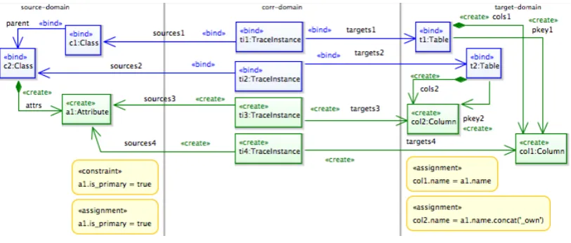
Figure 4: TGGs rule in EMorF notation
Within the available tools for TGGs, eMoflon2 has been widely considered as the reference one. It is able to deal with both batch and incremental model transformation [LAVS12] and it is realised as a set of two plug-ins: one add-in for the Enterprise Architect (EA) tool3and one plug-in for EMF. The usage of eMoflon is basically a two-steps-chaplug-in: the rule specification plug-inside EA, and the transformation execution inside EMF. Another emerging TGGs tool, developed from the FUJABA creators, is EMorF4which is an Eclipse Modelling Framework (EMF) tool
and offers, perhaps, an easier way to manage TGGs avoiding tools chains. It allows the modeller to graphically specify a model transformation between a source and target models conforming to some EMF metamodels. The TGG rules within a transformation scenario are specified by a set of
.emorf diagramfiles and grouped in a single.emorf file: this file is actually a metamodel with the
.emorf diagramfiles as elements. Once the rules are successfully specified, the transformation can be launched in forward, reverse or mapping mode.
Figure 4 depicts a TGG rule in EMorF notation; it represents one of the rules specifying the mapping between Attribute and Column described in Section 2. Intuitively, a TGG rule
specifies consistent mapping between elements of the source and target metamodels, e.g. in Figure4the metaclass Attributeof the source domain is mapped in the metaclassColumn
of the target domain. The separation of the metamodels is given by vertically splitting the rule in three areas. The top-part of the rule represents the pre-condition, whose elements are marked with the modifier <<bind>>; all the other elements marked with the modifier<<create>> compose the body of the rule. In the bottom part four OCL expressions are visible: they are used to constraint the rule behaviour, i.e. <<constraint>>, or to specify the value of some model element properties, i.e.<<assignment>>.
According to the transformation, the rule generates two columns for each primary attribute of a parent persistent class: one in the table generated from the parent class and one in the table generated from the child class. Additionally the columns are marked as primary key of the respective tables. Being more precise, the body of the rule is executed whenever the precondition is satisfied, thus each time two classes,c1andc2, related by a parent relationparent, map the corresponding tables, t1 andt2; consequently, each primary attribute a1of the parent class, is transformed in two columns, c1andc2, one for each table considered in the precondition; moreover the name of the columns is specified according to the OCL assignments on the target-domain side of the rule. The whole specification of the transformation is a set of nine rules.
4.2 JTL
JTL is a constraint-based model transformation language specifically tailored to support bidirec-tionality. The implementation relies on the Answer Set Programming (ASP) [GL88], which is a form of declarative programming oriented towards difficult (primarily NP-hard) search problems and based on the stable model (answer set) semantics of logic programming.
1transformation uml2rdbms(uml:UML, rdbms:RDBMS) { 2 ...
3 relation AttributeToColumn { 4 an, at : String;
5 enforce domain uml c:Class {
6 attrs = attr: Attribute { name = an, parent = c, is_primary = false } 7 };
8 enforce domain rdbms t:Table {
9 cols = col: Column { name = an, parent = t } 10 };
11 }
12 top relation SuperAttributeToColumn{ 13 enforce domain uml c: Class { 14 parent = sc: Class { } 15 };
16 enforce domain rdbms t: Table { 17 };
18 when {{ ClassToTable(c, t); } or { SuperAttributeToColumn(cc, t); cc = c.parentOf; }} 19 where { AttributeToColumn(sc, t); }
20 } 21}
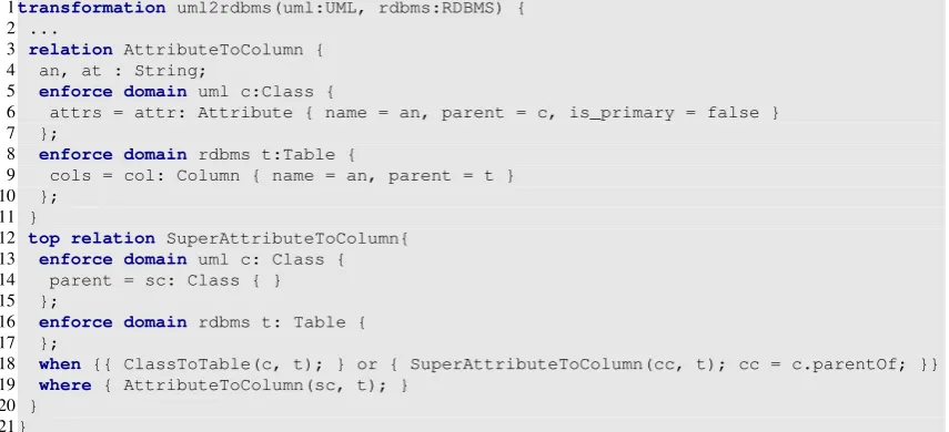
Listing 1: Fragment of the UML2RDBMS transformation in JTL
candidate models is specified as a set ofrelations that must hold for the transformation to be successful: in particular, it is defined by twodomains and includes a pair of whenandwhere
predicates which specify the pre- and post- conditions that must be satisfied by the elements of the candidate models. A transformation can be invoked forenforcementor ascheckonly. When invoked for enforcement, it is executed in a particular direction by selecting one of the candidate models as the target. A transformation can also be invoked in bidirectional mode by marking as enforcement both domain directions.
The semantics is given in terms of ASP. Thetransformation engineis written in the ASP lan-guage and consisting of bidirectional rules able to interpret the correspondences among elements and execute the transformation. Then the ASP solver finds and generates, in a single execution, all the possible models which are consistent with the transformation rules by a deductive pro-cess. A JTL program (as well as models and metamodels) is automatically translated into an ASP program. In order to understand how a model transformation is derived in ASP, we define a transformationTASP:= (Σ,R,C)which consists of a signatureΣspecifying the input and output
types of the transformation, a set of relationsR, which describe correspondences among element types of the source and target metamodels, and a set of constraintsC, which specify restrictions on the given relations. Relations between element types are derived from the relations of the JTL transformation, whereas constraints translate: (i) the model patterns that must be matched by the model elements of the domain and (ii) pre- and post-conditions that must be respected.
The overall architecture of the JTL framework has been implemented as a set of plug-ins of the Eclipse framework and mainly exploits the Eclipse Modelling Framework (EMF)5.It makes use of theDLV solver6(which has been wrapped and integrated in the overall environment) to execute transformations in both forward and backward directions.
Listing 1depicts a fragment of theUML2RDBMS transformation, which is expressed in the textual concrete syntax of JTL and applied on models given by means of their Ecore repre-sentation within the EMF framework. In particular, the following relations are defined: a) At-tribute2Column, which relates attibutes and columns in the two different metamodels andb) Su-perAttribute2Column, which relates attributes of the parent class to columns of the corresponding child table. Thewhenandwhereclause specify conditions on the relation. In particular, the when clause in Line18allow to navigate the parent classes of each attribute, then the where clause in Line19generates the correspondent columns. These relations are bidirectional, in fact both the contained domains are specified with the constructenforce.
According to the proposed approach, the designer task is limited to specifying relational model transformations in JTL syntax and to applying them on models and metamodels defined as EMF entities within the Eclipse framework.
5
Executing transformations in dedicated operational environments
In this Section we discuss the execution of theUML2RDBMStransformation specified by means of TGGs and JTL. To this end, the corresponding execution environments are considered and characterized with respect to highlighted features. In particular, we consider EMorF and eMoflon
for TGGs, and the JTL framework for the JTL language.
5.1 Scenario configuration 1
In this Section the UML2RDBMS transformation specified in the previous Section is executed in configuration 1 by means of EMorF, eMoflon and JTL framework.
5.1.1 Scenario configuration 1: EMorF
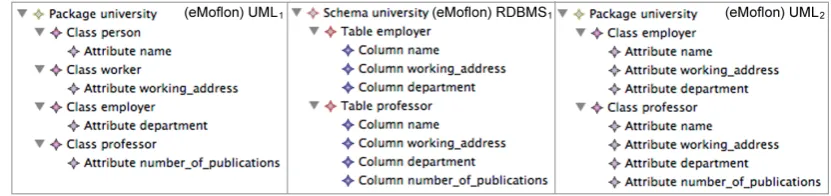
The models involved in the first scenario configuration are those in Figure2: the source UML model is basically a hierarchy of four classes: employerandprofessorare non-persistent in contrast withpersonandworker that are persistent. The forward execution of the trans-formation has unexpectedly generated theRDBMS1 model in Figure5 slightly different from the one depicted in Figure2: the tables employerandprofessorinstead of containing all the attributes inherited from all the parent classes, contain the column representing the owned attributes, and theworking addressandnumber of publicationsattributes, derived from thepersonandworkerparent classes. From the best of our knowledge, this issue is due to the EMorF implementation, which is not strictly aligned with the TGGs theory and does not support transitive-closures. Theoretically, in TGGs, it could be possible to navigate a model for obtaining all the necessary bindings, by means of OCL constraints. An example of such a constraint might be:c1→closure(parent)→includes(c2),wherec1 represents the child class andc2 the parent one. However, the current implementation of EMorF does not support the multiple bindings for the elements marked as<<bind>> in the rule specification. An improvement of the EMorF engine could overcome this lack of expressiveness.
Figure 5: Scenario configuration 1 - execution within EMorF
model in Figure 7). Conceptually, this is caused by the loss of information due to the non-surjectivity of the transformation that, being partial, does not involve all the source/target model concepts in the transformation itself. The naming convention, as other techniques, try to over-come this issue forcing the surjectivity of the transformation. It is important to note that, we presume a correct target UML model could be obtained introducing other naming conventions. Nevertheless such techniques, even if theoretically feasible, can be time consuming and error prone. Tracing mechanisms [PDK+11] might be employed to overcome all those issues due to non-bijectivity of the transformation: in such a case an improvement of the TGGs paradigm is re-quired in order to manage the tracing instances used to record also elements which are discarded during the transformation execution.
5.1.2 Scenario configuration 1: eMoflon
The considered scenario configuration has been realized as a batch transformation and its result is depicted in Figure6. Despite both EMorF and eMoflon rely on the same model transformation approach, thus TGGs, the result of the execution maintain some differences due to the maturity of the tools. More precisely, the forward transformation within eMoflon has produced the expected RDBMS model, i.e. the model in which the two persistent classesemployer,professorare correctly transformed along with all the attributes in the hierarchy. This was possible thanks to the usage of so called auxiliary rules and a runtime configuration mechanism. The former are normal unidirectional graph transformation rules which increase the expressiveness of the trans-formation (in our example they are used in order to perform the transitive closure). The latter is a mechanism which helps eMoflon to handle the non-determinism of a transformation, detecting any potential rule overlappings and asking to the user, i.e. at run-time, to solve ambiguities. Considering the backward execution, the generated UML model, i.e.U ML01in Figure6, still dif-fers from the expected one depicted in Figure2since it does not contain the two non-persistent classespersonandworker. It is important to note that the kind of information loss deriving from the different expressiveness of the two metamodels remain untreated.
Figure 6: Scenario configuration 1 - execution within eMoflon
5.1.3 Scenario configuration 1: JTL
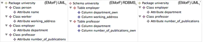
given in Listing 1 is able to produce exactly the expected target model (RDBMS1 model in Figure7), thus the tool is able to navigate all the parent hierarchy in the UML source model and to correctly generate all the columns in the RDBMS target model. In fact, JTL, by means of a series of recursive calls (e.g., in Line18of Listing1), is able to perform the transitive closure.
Even though the backward transformation is non-injective, the execution of the reverse trans-formation produces exactly the sameU ML1 model from which we started the transformation chain. In this case the correctness of the transformation is ensured by the usage of the JTL trace mechanism, which also keeps track of the non-transformed elements (in the considered example, they are classes thepersonandworkertogether with the parents relations).
Figure 7: Scenario configuration 1 - execution within JTL framework
5.2 Scenario configuration 2
In this Section the UML2RDBMS transformation specified in the previous Section is executed in configuration 2 by means of EMorF, eMoflon and JTL framework.
5.2.1 Scenario configuration 2: EMorF
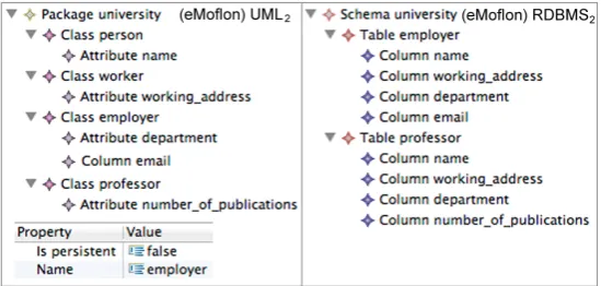
In this scenario configuration the models in Figure 3are taken into account. Essentially, they represent an evolution of the original models, and they have been defined in order to evaluate the change propagation facilities of the considered transformation tools. The changes operated on the model in Figure2b give place to additional difficulties related to the adopted naming conven-tion. In fact, a modeler might not be aware of all the modeling techniques used in the previous implementations and consequently could not be obvious that a columnemailwithout the suffix
depending on which class will be considered to be the owner. In our implementation, EMorF would not transform the columnemail meaning that it has been considered to belong to one of the two non-persistent classes (U ML2model in Figure8). But again, which one of the two? The naming convention, as well as any forcing mechanism, practically introduces further and not obvious issues, generally increasing the complexity of the transformation itself.
Figure 8: Scenario configuration 2 - execution within EMorF
Figure 9: Scenario configuration 2 - execution within eMoflon
5.2.2 Scenario configuration 2: eMoflon
As aforesaid eMoflon is able to realize both batch and incremental transformations. The consid-ered scenario configuration has been realized as an incremental transformation and the resulting models are those depicted in Figure 9. Within eMoflon, the changes introduced in this sce-nario configuration, i.e. the addition of the columnemailand the involvement of the property
with that modification. Theoretically, it could be possible to exploit the configuration mechanism to handle this non-functional choice with a set of dedicated rules, supporting the possibility to chose at run-time, which model the user wants to be generated. Nevertheless, even with help from the eMoflon developers, it was not possible to model this freedom of choice in the TGG as required for the scenario configuration due to limited expressiveness.
5.2.3 Scenario configuration 2: JTL
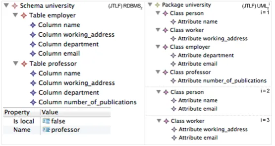
As previously mentioned, JTL is able to deal with non-injective situations by exploiting tracing information. However, considering theRDBMS2 model in Figure10, no trace information are available concerning the newly added elementemail, thus the non-injectity has to be solved generating all the feasible solutions consistent with the target models and with the changes. Being more precise, the transformation execution produces a set of three models: each one rep-resents a different solution where the columnemailis thought to come from each of the three different classes of the hierarchy. The ability to generate multiple solutions as result of a trans-formation come straight from the underlying ASP engine. Please note that, even if the property
is local(see theRDBMS2 model in Figure10) is not directly involved in the transformation (thus not mapped in the UML metamodel/model), its correctness is ensured by means of tracing mechanism.
Figure 10: Scenario configuration 2 - execution within JTL framework
5.3 Summary of the evaluation
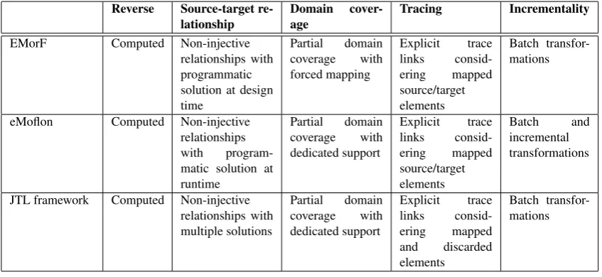
As shown in Table1, all the considered implementations (EMorF, Moflon, and JTL framework) do not require the explicit definition of the backward transformation. In fact, the reverse function is automatically computed by the tools themselves.
non-functional transformations and resolves multiple choices at runtime, perhaps demanding an hu-man interaction. Contrariwise, in these cases the JTL framework, by relying on the ASP theory, is able to generate all the possible models. In this way developers can focus on the implemen-tation of the transformation behaviour and can neglect the explicit management of non-injective cases (e.g., as done in the transformation given in Listing1).
The JTL framework offers a dedicated support, implemented by means of tracing mechanism, which permits to record all the information required to ensure the correctness of the transfor-mation when an infortransfor-mation loss occurs. This is shown, in the backward transfortransfor-mation imple-mentation of (i) the first scenario configuration in Figure7, when the JTL framework is able to re-generate the class hierarchy, including the two non-persistent classespersonandworker, and (ii) the second scenario configuration in Figure10, when the new propertyisLocalis re-generated. EMorF constrains the transformation with forced mappings which can be further added within the rule set: in such way the transformation is made total on the elements consid-ered in the transformation. This aspect emerges, for example, in the first scenario within EMorF, when we had to develop further rules for the missing elements. As aforesaid, eMoflon can be used for batch transformations, typically with information loss, or for incremental transforma-tions, where the old triple of models is incrementally modified to avoid information loss.
Reverse Source-target
re-lationship
Domain
cover-age
Tracing Incrementality
EMorF Computed Non-injective relationships with programmatic solution at design time Partial domain coverage with forced mapping Explicit trace links consid-ering mapped source/target elements Batch transfor-mations
eMoflon Computed Non-injective relationships with program-matic solution at runtime Partial domain coverage with dedicated support Explicit trace links consid-ering mapped source/target elements Batch and incremental transformations
JTL framework Computed Non-injective relationships with multiple solutions Partial domain coverage with dedicated support Explicit trace links consid-ering mapped and discarded elements Batch transfor-mations
Table 1: Summary of the evaluation
EMorF, as eMoflon as well, creates trace links between the transformed elements. In particu-lar, they only keep track of the elements involved in the transformation rules, but unfortunately this information is not used in further executions to solve ambiguities. EMorF is simply not incremental and only supports batch transformations. In this case one has to somehow resort to encoding the information (e.g., naming convention). Within eMoflon, incremental transforma-tions are used to avoid information loss.
JTL framework does not support incremental transformations.
This study reveals that the characteristics an approach is able to provide do not only de-pend on the transformation language, but some aspects are related on the operational environ-ments and their implementations. In fact, characteristics as reversibility or the ability to specify non-bijective transformations strictly depend on the transformation languages (in particular, we showed that both the theory of TGGs and the JTL languages provide them). On the other hand, the highlighted issues in dealing with critical aspects (i.e., loss of information, partiality, non-injectivity) are not limitations of the languages, but often depend from some precise implemen-tation choices as well as the maturity of the tools.
6
Related Work
As already mentioned, model transformation is intrinsically difficult, and its nature poses a num-ber of obstacles in providing adequate support for bidirectionality and change propagation. As a consequence a large number of proposals impose relevant restrictions of the characteristics of the involved transformations, i.e. mappings are required to be bijective. Such comparison is discussed in [HLR08]. [Ste08] organizes the existing bidirectional transformation solutions in different categories by distinguishing approaches based on QVT-R, graph transformation tech-niques, and XML-based options, to mention a few. Characterizations of model transformation languages based on the features they satisfy are presented in [CH06,MG06]. The taxonomy proposed in the latter aims to help developers in deciding which model transformation approach is best suited to deal with a particular scenario.
Stevens, in [Ste09], discusses bidirectional transformation focusing on basic properties which such transformations should satisfy: the paper considers QVT-R as applied to the specification of bidirectional transformation and analyse requirements and open issues. Furthermore, it points out some ambiguity about whether the language is supposed to be able to specify and support non-bijective transformations. Despite the potentiality of the language, its tool support remains limited. Currently Medini QVT7and ModelMorf8are two of the most used tools.
A number of different approaches based on TGGs have been proposed. Remarkable is the PROGRES approach [BHLW07] a TGG solution to create integration tools also taking care of non-deterministic cases. PROGRES demands users intervention to rule execution, meaning that users will have to foresee the effects of each rule application and choose the desired behaviour. Furthermore, a series of works dealing with correctness and functional behaviour of model trans-formations and model synchronizations based on TGGs exists. In particular, [HEGO10] shows how to increase the efficiency of TGGs without losing correctness and completeness and how the so-called filter NACs can be used to reduce the non-determinism of TGGs. [HEO+11] proposes a formal framework for model synchronisation where TGGs are used to generate bidirectional update propagation operations. Furthermore, the authors prove the correctness and completeness of the framework.
Some interesting solutions have been proposed as based on lenses [FGM+07], where lenses define a state-based framework for asymmetric synchronization. Lately the works on lenses shift
7http://projects.ikv.de/qvt
the focus on the delta-based framework for considering the symmetric synchronization [XCE+11]. Unfortunately, the management of non-bijective problems is not clearly addressed, even though it could be theoretically supported by means of delta merging and conflict resolution. Moreover, at now there exist no available implementations relying on such theories.
A number of interesting applications is available, varying from incremental techniques [HLR06, GW09] to the automation of transformation specifications by means of the inductive construction of first-order clausal theories from examples and background knowledge [BV09].
7
Conclusion and Future Work
Bidirectional transformations are a mechanism for establishing, and re-establishing, relationships among related models, in particular, when they are edited independently. In the last decades, bidi-rectionality has been acknowledged as a common denominator for a set of different applications as consistency management, synchronization, change propagation, and round-trip engineering.
In this paper, we have identified a set of features which characterize the bidirectional transfor-mation approaches and their implementations. Additionally, we have studied two of the existing approaches, namely TGGs and JTL, to validate the elicited features and to understand differences and similarities between them.
From this analysis arise how each one of these languages is characterized by a set of spe-cific properties pertaining to a particular application. In our opinion, the study of bidirectional transformations cannot neglect non-determinism and its management. There exist scenarios in which having multiple solutions to a model transformation problem is a desired outcome: in this respect, JTL is a promising approach for all the application involving change propagation where mappings can be non-injective and the transformation can be partial. Even though in our experience the time required to execute JTL model transformations is more than acceptable, the generation of a number of models may cause efficiency problems due to the models manage-ment. For this reason, a bidirectional language may choose to force the mappings to be bijective through additional constraints especially in those applications, which do not demand for multiple choices. TGGs are an effective mechanism in dealing with model synchronization as intended in [HLR08]: relying on bijective mappings, synchronisation does not expose TGGs to the issues related to the naming convention and the other described techniques.
Since the aforesaid applications seem require different combination of the highlighted fea-tures, as future work, we plan to investigate these exact configurations. Moreover, we propose to extend this analysis to further bidirectional model transformation approaches.
Acknowledgements
We would like to thank Anthony Anjorin for his precious contribution in this work. Furthermore, we would like to thank Alfonso Pierantonio, Davide Di Ruscio, Antonio Cicchetti and Lilija Klassen for their help and their comments.
Bibliography
[BHLW07] S. M. Becker, S. Herold, S. Lohmann, B. Westfechtel. A graph-based algorithm for consistency maintenance in incremental and interactive integration tools.Software and System Modeling6(3):287–315, 2007.
[BV09] Z. Balogh, D. Varr´o. Model transformation by example using inductive logic pro-gramming.Software and System Modeling8(3):347–364, 2009.
[CDEP11] A. Cicchetti, D. Di Ruscio, R. Eramo, A. Pierantonio. JTL: a bidirectional and change propagating transformation language. InProcs. of SLE 2010. LNCS 6563, pp. 183–202. Springer, 2011.
[CFH+09] K. Czarnecki, J. N. Foster, Z. Hu, R. L¨ammel, A. Sch¨urr, J. F. Terwilliger. Bidirec-tional Transformations: A Cross-Discipline Perspective - GRACE meeting notes, state of the art, and outlook. In ICMT2009. LNCS 5563, pp. 260–283. Springer, 2009.
[CH06] K. Czarnecki, S. Helsen. Feature-based Survey of Model Transformation Ap-proaches.IBM Systems J.45(3), June 2006.
[FGM+07] J. Foster, M. Greenwald, J. Moore, B. Pierce, A. Schmitt. Combinators for bidirec-tional tree transformations: A linguistic approach to the view-update problem.ACM Trans. Program. Lang. Syst.29(3), 2007.
[GL88] M. Gelfond, V. Lifschitz. The Stable Model Semantics for Logic Programming. In Procs. of the ICLP 1988. Pp. 1070–1080. The MIT Press, Cambridge, Mas-sachusetts, 1988.
[GW09] H. Giese, R. Wagner. From model transformation to incremental bidirectional model synchronization.Software and Systems Modeling8(1):21–43–43, 2009.
[HEGO10] F. Hermann, H. Ehrig, U. Golas, F. Orejas. Efficient analysis and execution of correct and complete model transformations based on triple graph grammars. In Proceed-ings of the First International Workshop on Model-Driven Interoperability. MDI ’10, pp. 22–31. ACM, 2010.
[HEO+11] F. Hermann, H. Ehrig, F. Orejas, K. Czarnecki, Z. Diskin, Y. Xiong. Correctness of Model Synchronization Based on Triple Graph Grammars. In MoDELS. Pp. 668– 682. 2011.
[HLR06] D. Hearnden, M. Lawley, K. Raymond. Incremental Model Transformation for the Evolution of Model-Driven Systems. In Procs. of MoDELS 2006. LNCS 4199, pp. 321–335. Springer-Verlag, 2006.
[HLR08] T. Hettel, M. Lawley, K. Raymond. Model Synchronisation: Definitions for Round-Trip Engineering. InProcs. of ICMT 2008. 2008.
[KS06] A. K¨onigs, A. Sch¨urr. Tool Integration with Triple Graph Grammars - A Survey.
Electronic Notes in Theoretical Computer Science148:113–150, 2006.
[LAVS12] M. Lauder, A. Anjorin, G. Varr´o, A. Sch¨urr. Efficient Model Synchronization with Precedence Triple Graph Grammars. InICGT. Pp. 401–415. 2012.
[PDK+11] R. F. Paige, N. Drivalos, D. S. Kolovos, K. J. Fernandes, C. Power, G. K. Olsen, S. Zschaler. Rigorous identification and encoding of trace-links in model-driven en-gineering.Software and System Modeling10(4):469–487, 2011.
[Sch95] A. Sch¨urr.Graph-Theoretic Concepts in Computer Science. Chapter Specification of graph translators with triple graph grammars, pp. 151–163. Springer, 1995.
[Sch06] D. Schmidt. Guest Editor’s Introduction: Model-Driven Engineering. Computer
39(2):25–31, 2006.
[SK03] S. Sendall, W. Kozaczynski. Model Transformation: The Heart and Soul of Model-Driven Software Development.IEEE Software20(5):42–45, 2003.
[Ste08] P. Stevens. A Landscape of Bidirectional Model Transformations. InGTTSE 2007. LNCS 5235, pp. 408–424. Springer, 2008.
[Ste09] P. Stevens. Bidirectional model transformations in QVT: semantic issues and open questions.Software and Systems Modeling8, 2009.
[Wit05] S. Witkop. MDA users’ requirements for QVT transformations. 2005. OMG docu-ment 05-02-04.