Volume 1 (2006)
Proceedings of the
Third International Workshop on Graph Based Tools
(GraBaTs 2006)
Specifying Distributed Graph Transformation Systems
Ulrike Ranger, Erhard Schultchen, and Christof Mosler
12 pages
Guest Editors: Albert Z ¨undorf, Daniel Varr ´o
Managing Editors: Tiziana Margaria, Julia Padberg, Gabriele Taentzer
Specifying Distributed Graph Transformation Systems
Ulrike Ranger1, Erhard Schultchen1, and Christof Mosler1
1RWTH Aachen University, Department of Computer Science 3,
Ahornstrasse 55, 52074 Aachen, Germany
[ranger|erhard|christof]@i3.informatik.rwth-aachen.de
Abstract: Graph transformation systems simplify software development by mod-eling the system in a visual and declarative language. Despite their expressive-ness, they fail to support specifiers in modeling distributed systems. As software projects increasingly demand support for distribution, we aim to fill this gap for graph transformation systems. With our concepts, specifiers can visually specify graph transformations affecting multiple applications simultoniously. Based on this visual specification, the corresponding distribution to the different applications is automatically derived. We introduce our concepts in general and demonstrate their applicability by means of an example.
Keywords:Graph Transformations, Distributed Systems, Visual Specification
1
Introduction
Graph transformation systems (GTS) provide suitable means to model complex applications vi-sually and in a declarative way. By declarative, we understand to model what an application should do instead ofhowthe result should be achieved. PROGRES [Sch91] is one representative of these systems and has been applied successfully in various large projects from different do-mains. However, PROGRES in particular and graph transformation systems in general provide only little support for modelingdistributedsystems. As modern large-scaled software projects often require the interaction of separated applications, this lack constitutes a severe drawback of GTS.
In common approaches for distributed systems, the coupling is modeled using textual elements like remote procedure calls or messages. This is even true for visual programming environments like Fujaba [FNTZ00]. E.g. [Tic02] describes the modeling of component-based systems using remote procedure calls. However, no support for modeling distributed graph transformations in a visual way is provided.
are left out in this paper as we focus on purely visual modeling of distributed systems.
The development of a distributed system is divided into two different steps: (1) Using an import/export mechanism,interfacescan be exchanged between specifications containing node and edge types. (2) The interfaces exported by specifications may be used to modeldistributed graph transformationsconcerning several applications. In this paper, we focus on the second step of modeling distributed systems, by a visual approach. Although this approach is very general, we focus on PROGRES in this paper.
Until now, our work does not especially focus on parallelism of distributed graph transfor-mations. As a distributed transformation is executed on separated computers, it is inherently executed in parallel. However, synchronization is solely assured by the underlying infrastructure and not modeled explicitly by the specifier. Research activities on parallel graph transformations are presented e.g. in [LETE04]. We are still investigating how these results can be included into our work.
The paper is structured as follows: InSection 2we introduce our concepts in a general form.
Section 3 gives an example for distributed system modeled in a visual way. Implementation aspects are presented inSection 4. The paper gives an outlook on future work inSection 5and is summarized inSection 6.
2
Distributed Graph Transformation Systems
In this section, we present our concepts for specifying distributed graph transformation systems in a visual way. These concepts will be illustrated in Section 3considering a simple process management system as example.
2.1 Structure of a Distributed System
In our concept, a distributed system is modeled in a similar way as a non-distributed software application. The standard proceeding is as follows: First, the structure and the behavior of the software is modeled within a specification consisting of a graph schema and of appropriate graph transformations. Afterwards, adequate source code for the specification is generated. This code can be executed e.g. as a prototype based on the UPGRADE framework [BJSW02]. The executed application stores a runtime graph representing the application’s state. Furthermore, the specified graph transformations can be applied via the prototype changing the state of the application and thus of the runtime graph.
In contrast to a non-distributed software application, a distributed system consists of several applications, which are in turn graph transformation systems. Each of these applications is de-veloped in the standard way (as described above), and is executed separately at runtime. Thus, every application stores its own runtime graph, and may perform graph transformations. To couple these applications, we usedistributed graph transformations, which affect several appli-cations simultaneously.
coordination of the distributed applications. It contains all information required for modeling the distributed transformations, like node and edge types1of the coupled applications. Figure 2
shows the structure of a sample distributed system, whose details will be explained in Subsec-tion 3.1. The coupling logic does not have to be modeled necessarily in an own specification, but otherwise the coupling logic has to be integrated in the specifications of the coupled appli-cations in addition to their actual functionality. As the coupling logic may be very complex and extensive, this may lead to confusing specifications, which are difficult to maintain.
2.2 Exchanging Specification Interfaces
Before distributed graph transformations can be visually specified, the Coupling Specification needs information about node and edge types of the coupled applications. Therefore, for each application aninterfaceis defined consisting of graph schema elements. The schema elements that should form the interface are marked with the<e>stereotype, an abbreviation forexport this element. The interface covers also public attributes of node types. Additionally, certain consistency and completeness constraints for the interface have to be checked. For example, for every edge type of the interface the node types of its source and target node have to be contained in the interface, too. If one constraint is violated, a corresponding error message is shown to the specifier. After defining the interfaces, the Coupling Specificationuses these interfaces by
importingthe node and edge types into its graph schema.
Used elements areread-onlyand thus can not be changed e.g. by adding a new attribute to a node type or changing the type of an attribute. Though read-only, the used schema elements can be applied within the specification similar to self-defined elements, e.g. in visual graph transfor-mations or queries. To distinguish between self-defined and used types within the specification, nodes and edges of used types are illustrated as striped rectangles resp. dashed arrows. The specifier can define edge types between self-defined and used node types or just between used types. That way, he integrates the imported schema elements into his specification, and defines new relations between schema elements of different applications. An example for exchanging interfaces is depicted inFigure 2described inSubsection 3.1.
2.3 Distributed Graph Transformations
Before distributed graph transformations can be modeled, we have to point out the difference between nodes and edges of used and of self-defined types: Nodes and edges of used types refer to remote objects, in contrast to nodes and edges of self-defined types, which refer to local objects like in non-distributed applications. Therefore, instances of used types are not stored in the Coupling Specification, but in the application which is based on the specification defining the element’s type. For sake of simplicity, we assume that every specification is executed exactly once within a distributed system. This simplifies determining the application storing the instance of a used type, as specifications may be executed simultaneously several times. Section 5will present appropriate concepts to relieve this restriction.
1 In the following we regard PROGRES graph transformations, but do not consider the two-level typing system.
We use reference nodes as helper structures for accessing remote objects, instead of repli-cating remote objects in the local runtime graph. In contrast, we do not store reference edges
as references in general are helper structures and have only little semantics. But the storage of reference nodes simplifies the realization of edges between nodes of different applications. Ref-erence nodes do not store any information except the location of the actual remote node. The management of references is implicitly handled by the application and the runtime environment. All operations performed on a reference node are transparently propagated to the remote node. For propagating remote operations and the management of reference nodes, we use the features of the database DRAGOS [B¨oh04] (seeSection 4).
Distributed graph transformations can be specified in a similar way as standard graph trans-formations. Subsection 3.2will give an example considering the distributed transformation of
Figure 3. Note that by using DRAGOS even distributed graph transformations are executed as transactions. The creation of a remote node is triggered in the same way as the creation of a node of a self-defined node type, i.e. by using the node only on the right-hand side of a graph transformation. Thus, a new node will be created in the remote application and an appropriate reference node is automatically inserted in the local graph, which stores a link to the remote node. To destroy a remote node, the corresponding variable is used only on the left-hand side of a transformation. This will cause the instance node to be located and deleted in the remote application. Consequently, the local reference node is deleted, too. The same mechanism is used for creating and deleting remote edges, which is triggered by applying used edge types.
As reference nodes are only helper structures, they are not created explicitly within transfor-mations, but instantiated on-demand in the local runtime graph. A reference node is inserted in two different scenarios: Either, the reference is automatically created when a new remote node is created (as described above), or if the corresponding node is used in the left-hand side of a transformation. In the latter case, the local application is searched for a reference node fulfilling the transformation conditions. If no adequate node is found, an appropriate node is requested from the remote application and a reference node is created in the local graph. The deletion of reference nodes is triggered automatically if the actual remote node is destroyed – independent of the application which has caused the deletion of the actual node.
Up to now, we have assumed that we can create and delete remote nodes and edges without any restrictions. In practice, additionalconstraintsmay apply for performing modifications on remote runtime graphs ensuring their consistency. For example, an additional actions for the consistency have to be performed. In some cases, it might even be required that an applica-tion forbids the creaapplica-tion or deleapplica-tion of nodes and edges by remote applicaapplica-tions as described in [HEET99]. For these reasons, we are developing arule engine, which will perform constraint validations at certain graph modifications and triggers actions preserving the consistency.
Requirements Definition successor Architecture
Software Architect
capability assigned
needs
...
needs
Requirements Specialist John Smith
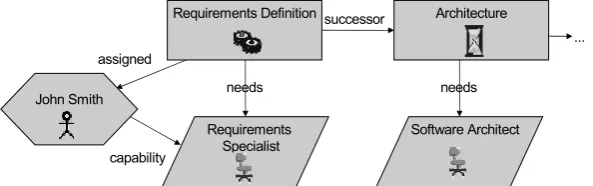
Figure 1: Sample runtime graph of the simplified PMS
to prove our concepts. For lack of space, in the next section we present only a little example according to the simplified approach and show the usage of the presented concepts.
3
Example
One of the largest PROGRES specifications is that of the process management system AHEAD [JSW00] (250 pages). Using AHEAD, complex development processes can be modeled and ex-ecuted. Managers get an overview of the process’s progress and developers receive an agenda of their tasks. A process management system (PMS) comprises different management aspects, so modularization is beneficial to retain maintainability. Also, the management aspects are com-monly used by different persons, and so the PMS is an interesting application for distributed systems.
This section illustrates the concepts explained in Section 2 by means of a simplified PMS.
Figure 1shows a simple runtime graph of this system for a software development project. The process in Figure 1is modeled by two tasks, Requirements Definitionand modeling of the soft-ware’sArchitecture. Other tasks like the implementation have been left out for lack of space. As requirements have to be defined before the architecture can be described, asuccessorrelation is modeled between the two tasks.
Resources are required to perform a task. For resource management, we distinguish between abstract resources and concrete resources. Abstract resources denote capabilities or roles (like
Requirements Specialist), whereas concrete resources refer to objects or persons (likeJohn Smith).
With theneedsedge, tasks express a demand for an abstract resource. For this abstract resource, an appropriate concrete resource has to be assigned before the task can be started. Here, the task
Requirements Definitionis associated with the abstract resourceRequirements Specialist. The
con-crete resource (person)John Smithis capable of working as aRequirements Specialist, as indicated by thecapabilityedge. Therefore, he is assigned to the task. As the task’s needs are fulfilled, it is put into the state ’started’ indicated by the gears icon.
specifica-Legend
Self-defined node class
Used node class Self-defined edge type Used edge type
<e> Export stereotype
Resource Manager Specification CR <e> <e> o:=f AR <e> * * Coupling Specification Specification AR R * * *
* 1 CR 1 1
o:=f T s:=d 1 1 Task Manager Specification * T <e> <e> s:=d
TM 1 *
uses uses
n n
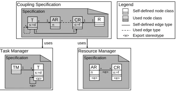
Figure 2: Distributed system modeled by different specifications
tions are coupled statically by means of their graph schemes. Afterwards, the system’s program logic is modeled using distributed graph transformations, providing the dynamic coupling.
3.1 Static Structure
The PMS depicted in Figure 2is split up into two separated Managers, which encapsulate in-dependent parts of the system’s functionality. For simplicity, only relevant attributes are shown. In the left-lower part of the figure, theTask Managerdefines the node typeTrepresenting tasks, which are ordered by a successor relation indicated by a reflexive edge type. Tasks have an at-tributesindicating their state, for examplein Definitiondif the task has been defined, but not yet started. The node typeTMmanages all tasks of a project and is used to group tasks. In the right-lower part, theResource Managermanages abstract and concrete resources. Abstract resources are modeled by node typeARand identified by an unique name attributen. Concrete resources CRmay be marked as free or occupied using a boolean attribute (o := fresp. o := t). The relation between both node types defines a capability.
Figure 2also depicts the Coupling Specification, which is used to couple both Managers. To model the Coupling Specification, the specifier needs to know parts of the Task and Resource Manager’s graph schema. These are provided by an import/export mechanism, which works as follows: First, the specifiers of the Manager specifications decide, which node and edge types should be accessible from outside the specification. These elements are marked as exported, depicted by<e> markers in Figure 2, and form the specification interface. Second, marked elements are exported in a textual document, which is passed to the Coupling Specification. Third, the specifier of the Coupling Specification imports the interfaces.
Coupling Specification
Specification
transformation assignConRes(t:T) =
Runtime-Graph Runtime-Graph
::=
Legend
Edge of a self-Defined edge type Specification
Runtime-Graph Node of a self-Defined node class a:AR t r:R c a t s:=r o:=t T1 AR1 CR1 T1 AR1 R1 Resource Manager Runtime-Graph Runtime-Graph AR1 CR1 CR1 o:=t AR1 Runtime-Graph Runtime-Graph T1 T1 s:=r Task Manager
Node of a used node class
Edge of a used edge type Local edge Reference node Local node c:CR o!=t
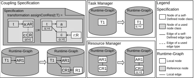
Figure 3: Transformation for assigning a concrete resource
edge types between two used node types: The edge type connectingTandCRis defined locally in the Coupling Specification and indicates the assignment of resources to tasks. Note that this connection cannot be modeled within a Manager specification as only one of the connected node types is available in each of them.
Graph transformations modeled in the Coupling Specification can use both self-defined and used elements. Utilizing used elements invokes remote applications at runtime. To execute the transformation, its distribution to the corresponding Managers is derived automatically. We demonstrate such a transformation in the following section.
3.2 Dynamic Coupling
As an example for a distributed graph transformation, the transformationassignConResfor find-ing a concrete resource for a task is presented. For the task’s abstract resource, a concrete re-source is requested from the Rere-source Manager and assigned to the task. The concrete rere-source must fulfill the abstract resource and may not be assigned to another task. Furthermore, a rating for the concrete resource is created and the task’s state is changed. Based on the Coupling Spec-ification’s graph schema ofFigure 2, we model the transformationassignConResas depicted in
Figure 3, given tasktof node typeTas an input parameter. The transformation looks similar to a local transformation in the Coupling Specification2.
In the left-hand side of the transformation, tasktis shown with its assigned abstract resource
a. Moreover, a nodec of node typeCR is required, which fulfills the abstract resource a, and
whose attributeoshould be unequal to valuet. As all nodes within the left-hand side are of used node types, they are represented as striped rectangles. In contrast to the edge incident tot, the edge connecting the abstract resourcea and the concrete resourcecis dashed, representing an used edge type.
The right-hand side of the transformation defines the effects of applying the graph transfor-mation rule. Besides the nodes and edges of the left-hand side, a new noderof node typeRis
2 For sake of simplicity, we do not follow the PROGRES syntax exactly, instead we use an abstract syntax where
depicted. This node is created by the transformation and connected to the concrete resourcec by an edge. The rating node is used to assess the concrete resource. Additionally, a new edge is created connectingtwith the found concrete resourcec. Furthermore, the attributes oftandcare updated representing their execution status and the occupied status, respectively.
The effects of the transformation’s execution on the applications are also depicted inFigure 3: For each application two runtime graphs are shown, describing sample runtime graphs before and after the transformation. In the Task Manager, only the attribute sof task T1(represented by nodetin the transformation) has to be modified. No modifications have to be performed to the corresponding reference nodeT1in the Coupling Specification. In the Resource Manager, the attribute o of the concrete resource CR1 (represented by node c in the transformation) is set to t indicating its occupation. In the runtime graph of the Coupling Specification, a new reference node pointing toCR1in the Resource Manager is inserted. Furthermore, two new edge are created: one connectingCR1andT1, and one edge connectingCR1and the new objectR1 (represented by noder in the transformation). Please note, that the edge betweenCR1andAR1 does not exist in the Coupling Specification because reference edges are not stored.
4
Realization
As our approach is very general, we are currently implementing the basic functionality not only in PROGRES, but also in the open-source CASE tool Fujaba [FNTZ00]. Both systems have been extended by an import/export functionality using the standardized XMI format as a com-mon textual exchange format for interfaces. Furthermore, we have adapted both systems so that used elements cannot be modified by the specifier. For the implementation of distributed graph transformations, changes to the code generation of PROGRES and Fujaba have been made. De-tails on the modifications are presented in [RL06].
The code generated requires some special functionality which has to be provided by the under-lying infrastructure. This functionality can be subsumed under the following four requirements: (1) The runtime state of each application has to be stored persistently; (2) for the realization of reference nodes, each application has to provide unique identifiers for remotely accessible nodes; (3) concurrent modifications to an application’s runtime graph by several remote applications have to be handled w.r.t. the ACID properties known from databases; (4) for the implementa-tion of the rule engine menimplementa-tioned in Subsection 2.3, an event mechanism has to inform rules about changes to the local runtime graph. These rules check violated consistency constraints and trigger appropriate transformations.
The four requirements are fulfilled by the graph-based database DRAGOS, which is already used by PROGRES prototypes for the persistent storage of the runtime graph. Similar support for applications generated by Fujaba has recently been added. Due to its extensible architecture, DRAGOS can easily be extended for operation in distributed systems. For example, we have implemented a new transaction manager for distributed transactions using the two-phase-commit protocol.
communi-Coupling Specification
Specification
transformation delegateNewTask(t:T) =
::= t dt:T
t
distribution t = „contractor“; dt := „subcontractor“; end;
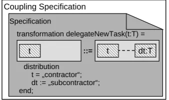
Figure 4: Transformation for delegating a task
cation required for message-based coupling is provided by an appropriate service, too. CORBA also provides a distributed transaction manager, which is used to coordinate the applications’ local transaction managers. However, other middleware architectures, like RMI, could be used for this purpose as well, as the middleware is only an implementation detail.
Our conceptual work focuses on visual and declarative modeling of distributed systems. There-fore, we do not concentrate on network-related details of the coupling, which have been devel-oped in the area of distributed systems. For example, modern distributed systems often provide caching of data to reduce the amount of queries sent accross the network. Another example is fault-tolerance usually achieved through replication. Although these aspects are interesting for the practical use of distributed systems, they do not affect the visual modeling of these systems.
5
Coupling of Similar Specifications
InSection 2 we have assumed that every specification is executed exactly once within a dis-tributed system. Thus, we determine the application in which a remote object is located by its underlying specification defining the object’s type. This is too restrictive for the practical usage, as also the multiple execution of a specification is desirable. For example, several companies may use their own Task Manager, and cooperate by delegating tasks to other companies, as described in [HJ04]. Thus, the specification of the Task Manager is executed several times in parallel. Therefore, we have to distinguish between applications based on the same specification but located in different applications. For this purpose, we will introduce appropriate means at specification time and at runtime.
objects can be defined. InFigure 4, we specify that the application owning the taskthas to fulfill
thecontractorrole. On the other hand, a remote application is searched, taking over the role of a
subcontractor. As every application can only fulfill one role within a certain relationship, the two
applications have to be different at runtime. A relationship concerns the instance-level, so that a application can fulfill different roles regarding different objects. For example, an application can
be asubcontractoras well ascontractordependent on the task.
At runtime, a configuration fileis used to assign roles to the available applications. Addi-tionally, an order can be specified for applications based on the same specification and having the same role. Depending on the configuration file, the concrete applications for remote objects can be determined fulfilling the role constraints. In future, we will analyze, which language constructs are needed and how the configuration of the applications can be supported best.
6
Conclusion
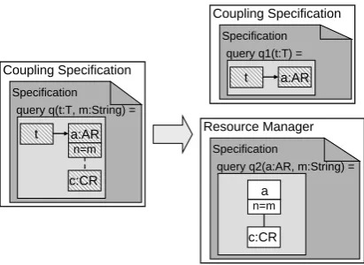
In this paper, we described concepts for visually modeling distributed systems using graph trans-formation systems. Each application of the distributed system is specified in a similar way to a non-distributed application. Additionally, interfaces for the applications have to be defined, which consist of node and edge types and can be used by other specifications. Used elements are read-only and displayed differently within the specification indicating their remote character. Knowing node and edge types of other specifications, distributed graph transformations can be specified in a visual way. At runtime, the specifications are executed in different applications, which interact according to the distributed graph transformations. The usage of reference nodes pointing to remote nodes enables to access and to relate remote objects. As we are at the begin-ning of visually specifying distributed graph transformations, we have to evaluate our presented concepts with regards to paths, negative application conditions, and folding of nodes.Our ap-proach is advantageous, as the specifier only has to model the coupling logic in a visual way analogously to a non-distributed specification. Based on the visual specification, the correspond-ing distribution to the different applications is automatically derived. They can be integrated in the existing PROGRES language and are easy to use as they follow the PROGRES semantics for local graph transformations. Furthermore, our approach offers potential for useful extensions, as the following two examples show.
Coupling Specification
Specification query q(t:T, m:String) =
c:CR a:AR t
n=m
Coupling Specification
Specification query q1(t:T) =
a:AR t
Resource Manager
Specification
query q2(a:AR, m:String) =
c:CR a n=m
Figure 5: Dividing a distributed pattern
a, thus reducing the complexity of the pattern search. Without the parameterization, query q2
would consist of the two unbound nodesaandcincreasing the search complexity. At runtime, these patterns are sent to the corresponding applications, which in turn reply their results. The results of all partial patterns determine the match of the entire distributed pattern.
Furthermore, we will extend our import/export mechanism by introducing abstract graph views. In the current approach, every specification interface consists of a graph schema part. In abstract graph views, abstract graph elements can be exported, which represent several con-crete graph elements in the local graph. To model such graph views, the specifier has to define appropriate rules for abstract elements using the rule engine mentioned inSubsection 2.3. The rules define the mapping of abstract elements to several concrete elements. Additionally, they define the actions, which have to be performed when an abstract element is created, deleted or changed by a remote application.
Bibliography
[BJSW02] B. B¨ohlen, D. J¨ager, A. Schleicher, B. Westfechtel. UPGRADE: A Framework for Building Graph-Based Interactive Tools. In Mens et al. (eds.), Graph-Based Tools (GraBaTs 2002). ENTCS 72. Elsevier Science, 2002.
[BR04] B. B¨ohlen, U. Ranger. Concepts for Specifying Complex Graph Transformation Sys-tems. In Ehrig et al. (eds.), Graph Transformations: 2nd Intern. Conf., ICGT 2004. LNCS 3256, pp. 96–111. Springer-Verlag, 2004.
[B¨oh04] B. B¨ohlen. Specific Graph Models and Their Mappings to a Common Model. Pp. 45– 60 in [PNB04].
Theory and Application of Graph Transformations,6thIntern. Workshop, TAGT’98. LNCS 1764, pp. 296–309. Springer-Verlag, 2000.
[HEET99] R. Heckel, H. Ehrig, G. Engels, G. Taentzer. A View-Based Approach to System Modeling Based on Open Graph Transformation Systems. In Ehrig et al. (eds.),
Handbook on Graph Grammars and Computing by Graph Transformation: Applica-tions, Languages, and Tools. Volume 2, pp. 639–668. WORLDSCIENTIFIC, 1999.
[HJ04] M. Heller, D. J¨ager. Graph-Based Tools for Distributed Cooperation in Dynamic Development Processes. Pp. 352–368 in [PNB04].
[JSW00] D. J¨ager, A. Schleicher, B. Westfechtel. AHEAD: A Graph-Based System for Mod-eling and Managing Development Processes. In Nagl et al. (eds.), Applications of Graph Transformations with Industrial Relevance, International Workshop, AG-TIVE’99. LNCS 1779, pp. 325–339. Springer-Verlag, 2000.
[LETE04] J. de Lara, C. Ermel, G. Taentzer, K. Ehrig. Parallel Graph Transformation for Model Simulation applied to Timed Transition Petri Nets. In Heckel (ed.), Proceedings of the Workshop on Graph Transformation and Visual Modelling Techniques, GT-VMT’04. ENTCS 109, pp. 17–29. Elsevier Science, 2004.
[PNB04] J. L. Pfaltz, M. Nagl, B. B¨ohlen (eds.).Applications of Graph Transformations with Industrial Relevance,2nd Intern. Workshop, AGTIVE 2003. LNCS 3062. Springer-Verlag, 2004.
[RL06] U. Ranger, M. L¨ustraeten. Search Trees for Distributed Graph Transformation Sys-tems. In Karsai and Taentzer (eds.), 2ndInternational Workshop on Graph and Model Transformation, GraMoT’06. Electronic Communications of the EASST 4. Euro-pean Association of Software Science and Technology (EASST), 2006.
[Sch91] A. Sch¨urr. Operationales Spezifizieren mit programmierten Graphersetzungssyste-men. PhD-Thesis, RWTH Aachen, 1991.
[Tae96] G. Taentzer. Hierarchically Distributed Graph Transformation. In Cuny et al. (eds.),
Graph Grammars and Their Application to Computer Science,5thIntern. Workshop. LNCS 1073, pp. 304–320. Springer-Verlag, 1996.