Volume 12 (2008)
Formal Modeling of
Adaptive and Mobile Processes
Using Resources as Synchronizers to Manage
Mobile Process Adaptation
Paolo Bottoni, Fabio De Rosa and Massimo Mecella
20 pages
Guest Editors: Julia Padberg, Kathrin Hoffmann
Managing Editors: Tiziana Margaria, Julia Padberg, Gabriele Taentzer
Using Resources as Synchronizers to Manage
Mobile Process Adaptation
Paolo Bottoni1, Fabio De Rosa1 2and Massimo Mecella2
1
Dipartimento di Informatica “SAPIENZA” Universit`a di Roma, Italy
2
Dipartimento di Informatica e Sistemistica “SAPIENZA” Universit`a di Roma, Italy
Abstract: Process management in Mobile Ad-hoc NETworks (MANETs) has to
deal with different types of tasks and resources. Teams can be formed with specific goals, such as recognition of a damaged area for disaster assessment, where each member of a team is assigned some task to be performed according to some policy. However, in real situations, it is possible that task assignments and policies have to be revised due to different causes. In addition to typical causes for dynamic changes in adaptive workflows, mobility introduces some specific problems, e.g. the need for new connectivity-maintaining tasks, or reassignment of tasks originally for members who have become unreachable, or who have no sufficient resources to complete the original plan. As these modifications occur dynamically, it is difficult to manage them through hard-coded programs. Rather, we propose the use of a rule-based for-malism, expressed in terms of multi-set rewriting. This supports a resource-centered view, in which both data-dependencies between tasks and plan-dependent ordering of tasks are expressed as production and consumption of resources of different types. In turn, rules are themselves seen as resources, so that they are prone to the same rewriting process, in order to redefine process schemas. The paper illustrates these notions and formalisms, and shows some cases of their application.
Keywords:Mobile ad hoc networks, adaptive workflows, multiset rewriting.
1 Introduction
Process management inMobileAd-hocNETworks (MANETs [AZ03]) has to deal with different
types of tasks as well as of resources involved.MANETsare networks of mobile devices
As an example, Figure1(a) shows a process schema for a team (e.g., of the Homeland Security Department), equipped with mobile devices (laptops and PDAs), to carry out after an earthquake or a hurricane. The process comprises several tasks: swimlanes represent the assignment of
tasks to team members1. In detail, the process requires that, after a visual analysis of a building,
supported by some map-based application, team member 1 (using his/her device) fills out a report and enters attributes and graphic data related to the damage. The team leader analyzes these reports and spatial data with the help of specific software to schedule the next activities. Team member 3 takes pictures of the precarious buildings, whereas team member 2 is in charge of processing old and recent photos of the site (e.g. to identify architectural anomalies). In this situation, matching new pictures with previous ones might be useful. Suppose that, in the team, there is only one PDA equipped with a photo-camera (e.g., that of team member 3). Therefore, during process enactment, when the condition of the OR-split (the diamond construct) managed
by team member 1 istrue, the member requires the execution of another instance of the task
“Take Pictures”. In general, the two task instances might be carried out in parallel but, since there is only one member equipped with the needed device, one of the two instances has to be
postponed. Figure1(b) shows a possible restructuring of the process.
A process management system (PMS) supporting such processes has therefore to deal with modifications of plans through insertion of new tasks, removal of originally planned tasks, or redefinition of task ordering, as well as reassignment of tasks from one member to another. As these modifications occur in a dynamical manner, it is difficult to manage them through
hard-coded programs. Therefore, we propose an ECA (Event/Condition/Action [Pat99]) approach for
adaptation in process management, by specifying which events (e.g. resource unavailability) can produce possible process restructuring and the set of transformation rules stating the control actions to be performed for adaptation. Such a rule-based approach is highly flexible, as rules are able to react to events at any time during process execution without making assumptions about when these events occur. This is in contrast to the addition of conditional branches to process
definitions [SSO01], which does not fit with frequently changing environments such asMANETs.
Specifically, in this paper we propose the use of a rule-based formalism, expressed in terms of multi-set rewriting, which supports a resource-centered view, in which both data-dependencies between tasks and plan-dependent ordering of tasks are modeled through resources of different types. Rules are themselves seen as resources, so that they are prone to the same rewriting process, in order to redefine plan management or different ways to achieve the same results.
The paper is structured as follows: in Section2, the general framework supporting process
adaptation inMANETis presented. In Section3, we give an overview of theWIPPOGlanguage
and its computation model, which is used as the language for rule definition. Section4details
on the proposed rule-based formalism, while Section5 applies the rewriting machinery to the
scenario above. Finally, in Sections6and7we discuss related work and conclude the paper.
1 Tasks belonging to swimlanes with the same name are intended to be assigned to the same team member (e.g.,
Compile Questionnaire 1
Photos
Matching
Compile
Report Result 1 Data Q1
Team Leader
Team Member 1 Team Member 2 Team Member 3
Take Pictures Compile
Questionnaire 2 Data Q2
Team Member 3
Take Pictures
Matching
Compile Questionnaire 3
T F
Data Q3
Photos Result 2
Compile Questionnaire 1
Photos
Matching
Compile
Report Result 1 Data Q1
Team Leader
Team Member 1 Team Member 2 Team Member 3
Take Pictures Compile
Questionnaire 2 Data Q2
Team Member 3
Take Pictures
Matching
Compile Questionnaire 3
T F
Data Q3
Photos Result 2
(a) Process
Compile Questionnaire 1
Photos Matching
Compile
Report Result 1 Data Q1
Team Leader
Team Member 1 Team Member 2 Team Member 3
Take Pictures Compile
Questionnaire 2 Data Q2
Team Member 3
Compile
Questionnaire 3 Data Q3
Take Pictures
Matching
T F
Photos
Result 2 Compile Questionnaire 1
Photos Matching
Compile
Report Result 1 Data Q1
Team Leader
Team Member 1 Team Member 2 Team Member 3
Take Pictures Compile
Questionnaire 2 Data Q2
Team Member 3
Compile
Questionnaire 3 Data Q3
Take Pictures
Matching
T F
Photos
Result 2
(b) Modified process
2 General Framework
Aprocess schemais a description of a business process in sufficient detail that it can be directly
executed by aprocess management system[WMC06]. It consists of a set oftasksto be performed
according to a specifiedscheduling(control flow), and undertaken byroles, defining
organiza-tional entities, such as humans or devices (actors). An executing instance of a process schema is
called acaseorprocess instance. Atask is an atomic unit of work which is run to completion
once initiated. We assume that each process has a uniquestart taskand a uniqueend task.
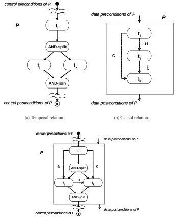
Since tasks may be executed in different orders, it is useful to identify conditions enabling their execution. These can be related to both data and control flows. Therefore, each task has pre-conditions holding before the task is carried out and post-conditions which should hold after
task execution. As an example, in the sub-processPof Figure2(c), tasktkhas(i)a pre-condition
on control flow: ti has to be carried out in order that the execution oftk can start; and(ii) a
pre-condition on datacandbthat holds after the execution of bothtiandtj.
Control flow occurs via thecontrol channel, which is usually indicated by a solid arrow
be-tween tasks. Control channels represent the business policies of the process; they describe
tem-poral relations among process tasks, i.e. when a task can be carried out with respect to the
execution of other process tasks. As an example, Figure2(a) describes the business policy of the
processPdepicted in Figure2(c). In this case, both taskstj andtkmust be carried out after the
execution ofti;tjandtkcan be carried out concurrently.
There may also be a distinct data channel between process tasks for communicating data
elementsbetween two tasks. Where a distinct data channel is intended, it may be illustrated with
a dotted line. The data channel representscausal relationsamong process tasks. It describes data
dependencies between two tasks and establishes when data pre-conditions of a task are satisfied
with respect to data obtained from the execution of other tasks. As an example, in Figure2(b)
data dependencies between tasks are reported. In this case, tasktj can be carried out after the
execution ofti(it consumes the dataa), but before the execution oftk; moreover,tkcan be carried
out only after the execution ofti andtj (it needs both databandc).
In the model proposed in this paper, the exchange of data between tasks is modelled through
the exchange ofdata resources: a process schema is associated with a finite multi-setGof data
resources. Each resourced∈Ghas a specific type, and there may be several instances ofdinG
at the same time. We usually callGthedata resource pool(drp) of the process.
Under this perspective, each task t may be considered as a producer/consumer of data
re-sources. It takes some data resources as input (data pre-conditions) and produces other data
resources as output (data post-conditions), i.e. t:DI(DO. In general, the data pre-conditions
and post-conditions of a task can be considered as finite multi-sets over a specific data alphabet
Π, so that a taskt can be modeled as a multi-set rewriter2. Its execution consumes fromdrpa
multi-set of data resources satisfying its data pre-conditions, and produces a new data resource
pool (drp0) according to its data post-conditions. We also say thatdrp0derives fromdrpthrough
t, and denote it with drp=⇒t drp0. As regards the input parameters of the process schema,
they constitute the data pre-conditions of the start task, whereas the output parameters are the post-conditions of the end task.
ti
AND-split
tj tk
AND-join
control preconditions of P
control postconditions of P
P ti
AND-split
tj tk
AND-join
control preconditions of P
control postconditions of P
P
(a) Temporal relation.
ti
tj
tk
a
b c
data preconditions of P
data postconditions of P
P
ti
tj
tk
a
b c
data preconditions of P
data postconditions of P
P
(b) Causal relation.
a
b
c
data preconditions of P
data postconditions of P
P ti
AND-split
tj tk
AND-join
control preconditions of P
control postconditions of P
a
b
c
data preconditions of P
data postconditions of P
P ti
AND-split
tj tk
AND-join
control preconditions of P
control postconditions of P
ti
AND-split
tj tk
AND-join
control preconditions of P
control postconditions of P
(c) Example of process schema.
The same idea can be applied for process execution with respect to control flow. The execution
of a processP is modelled as producing/consuming special synchronization (synch) resources
representing its progress state. Consumption and production of synch resources follows the
scheduling defined in the process schema. A process task is ready to be carried out (isenabled)
at a certain time of the process execution if its enabling synch resources are present in the synch
resource pool (srp) of the process. According to this vision, a process taskt:SI (SOcan be
considered as a rewriter of synch resource multi-sets; specifically, it consumes a multi-set of
synch resources satisfying its control pre-conditions SI from a synch resource pool (srp), and
produces new resources in the synch pool (srp0) according to its control post-conditions SO.
Again, we say thatsrp0 derives fromsrpthrought, and we denote it withsrp=⇒t srp0.
The combination of data and control flow specifications defines the order for task execution, by identifying data and synch conditions enabling their execution. Therefore, the enactment of a process is concurrently driven by both specifications, usually given through different notations.
To give a uniform and coherent representation of both data and control flow specifications
of a process P, we consider a correspondent set of multi-set rewriting rulesP, named
PMR-system(Process Multi-set Rewriting system), by taking the union of the two multi-set rewriting systems defined by the data and control flows (we assume resources are named differently in the two systems). Moreover, in modelling process adaptation, PMR-system rules are also seen as resources, and a set of high-level rewriting rules consumes/produces them in order to redefine
the schema. Specifically, ifPMRSis a PMR-system associated with a process schemaP, andRP
andRP0 are the sets of rules describingPbefore and after, respectively, the adaptationa, then
the execution ofaproduces a change fromRPtoRP0. We also denote this withRP=a⇒R
P0.
3 WIPPOG Model and Environment
In this section we give an overview of the WIPPOG (WHEN, IF, PROCESSES, PRODUCES,
OUTS, and GETS) language and computation model [BDD+04], used here to describe rules
representing both process schemas and process adaptations.
WIPPOGprovides a common framework for specifying transitions expressed through different
visual notations. It is based on the notion of a processtransitionand details out different aspects
of its pre- and post- conditions. Processes are assumed to occur within entities taking part in
some computational system, calledagents. An agent is endowed with a set of rules defining its
possible behaviours, and a pool of resources describing its state at any given time. Aresourceis
an item with a typetin a setT, anidentifieruniquely defining it, and an optional set of attributes
with values on well-established domains. The set of all resources onT is calledW(T).
The effect of a transition is modelled as consumption/production of resources as specified by WIPPOG rules. WIPPOG distinguishes internal resources, which have to be present in the
agent, from external resources that an agent has received from its environment. In a similar way, resources may be produced to remain in the pool defining the agent state, or to be spread out in the environment, possibly to be exploited by other agents.
S1 a S2
S1 a S2
(a) A transition in a finite state automata.
Task a p_1
p_2
p_3
2
1
1
Task a Task a p_1
p_2
p_3
2
1
1
(b) A transition in a Place/Transition net.
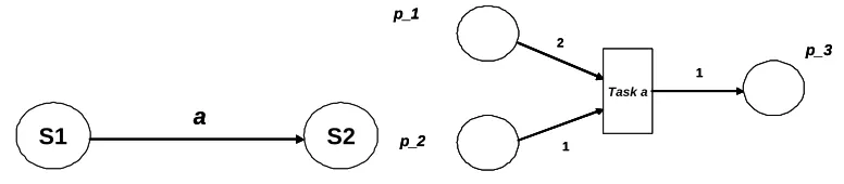
Figure 3: Examples of transition systems modelled byWIPPOGrules.
and matching is performed against values of existing resources. AWIPPOGrule is thus formed by the following six components:
WHEN: internal resources which have to be available to the process. Attributes can appear, with
either a constant value or a variable name.
GETS: externally produced resources which have to be available to the process. Attributes can
appear, with either a constant value or a variable name.
IF: a predicate in which variables appearing in the WHEN or GETS components can occur.
PROCESSES: computational activities associated with the transition. They are considered to
be always successful. Assignments to attribute values for the new resources produced by the transition are specified here.
PRODUCES: resources which have to be internally created as result of the transition execution.
If variables appear, their names have to be present either in the WHEN or GETS components, or in the left-hand side of an assignment in the PROCESS component.
OUTS: resources which are externally available as a result of the transition execution. If variables
appear, their names have to be present either in the WHEN or GETS components, or in the left-hand side of an assignment in the PROCESS component.
The application of aWIPPOG rule(i)matches resources mentioned in the WHEN and GETS
components with resources from the (resp., internal and input) resources pools; (ii)if a match
exists and also satisfies the conditions in the IF component, then: (a)removes the matched
re-sources;(b)executes the activities specified in the PROCESSES component; and(c)produces
(either for internal or external use) the resources specified in the PRODUCES and OUTS com-ponents, placing them in the internal or output resource pools, respectively. An agent cannot directly add something to its own input pool, nor can it remove anything from its output pool.
As an example, Figure3(a) shows a transition from stateS1 to stateS2 on inputain a finite
state automata. By using a resourcecurrentto indicate the current state and a resourceinputto
wrap symbols from the automata alphabet, we have the followingWIPPOGrule:
Rules ActivatorWIPPOG
WIPPOG Machine
WIPPOG Interpreter
Input
Output Resource Pool
Rules ActivatorWIPPOG
WIPPOG Machine
WIPPOG Interpreter
Input
Output Resource Pool
Figure 4: The architecture of aWIPPOGmachine.
GETS: input(value = ‘‘a’’)
PRODUCES: current(name = ‘‘S2’’)
Figure 3(b) specifies a Place/Transition Petri net, in which a transition consumes two tokens
from place p 1, one token from place p 2, and produces one token in place p 3. Using an
integer-valued attributetokensto denote the number of tokens in a place, and a resourceplace
to indicate the places involved in the transition, the followingWIPPOGrule results:
WHEN:place(id = p 1; tokens as X),
place(id = p 2; tokens as Y), place(id = p 3; tokens as Z) IF:X≥2, Y ≥1
PROCESSES:X1 :=X−2,Y1 :=Y−1,Z1 :=Z+1
PRODUCES:place(id = p 1; tokens as X1),
place(id = p 2; tokens as Y1),
place(id = p 3; tokens as Z1)
The modification of a given resource is modelled inWIPPOGby presenting the resource with
the same identifier in both the WHEN and the PRODUCES components. Attributes in such resources maintain their values, if not specified otherwise.
AWIPPOGmachine(WM) provides a computational environment to executeWIPPOGrules. It
consists of (see Figure4): aWIPPOGInterpreter, applying oneWIPPOGrule at a time, from those
present in theRulesbase, coherently with the role of the different components and according to
an activation policy managed by theWIPPOGActivator. The WIPPOGexecution process acts on
both theResource Poolwhich contains the resources describing the state of the agent, and the
InputandOutputcompartments of theWM, which allow its communication with other processes.
An interpreter tries the activation of a rule every time it is requested by an activator; theWIPPOG
Activatoris therefore responsible for implementing policies and managing the resources pool,
thus realizing a transitionstep.
WML Adaptation level
WM1
WM2 WMN
. . .
Local level
Team Member 1’s Device
Team Member N’ s Device Team Member 2’ s
Device
Team Leader’s Device WML
Adaptation level
WM1
WM2 WMN
. . .
Local level
Team Member 1’s Device
Team Member N’ s Device Team Member 2’ s
Device
Team Leader’s Device
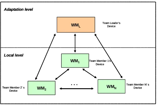
Figure 5: The hierarchical set ofWIPPOGmachines modelling the proposed framework.
machines (WMs) (see Figure 5): a WM at the adaptation level and WMs at the local level.
The high-level WM manages dynamic changes which can occur during process enactment, by
executing specificWIPPOGrules needed to adapt the process. With respect to our scenario, such
a machine should be running on the team leaders’ device. On the other hand, local WMs are concerned with the actual execution of tasks, and should be running on devices belonging to other team members. Therefore, in our system we have multi-set rewriting rules which act at two levels i.e., at the adaptation level and at the execution (local) level.
WIPPOG is relatively small (∼250Kb), so that it can be loaded on a powerful PDA running a
Java Virtual Machine. However, if some member has not sufficient power, an image of its policy pool can be kept at the team’s leader device and managed from there.
4 The Rule-based Formalism
Before describing local and adaptation rules, we give concepts and terms about multi-sets and rules, matches and direct derivations. We set this work in the context of High-Level Replacement
Systems, of which multisets are an instance [GPS98] .
A multi-setGover an alphabetΠis a function fromΠinto the natural numbersN such that
only a finite number of elements fromΠis assigned a non-zero function values, i.e.:G:Π→N,
anda∈G if and only if G(a)>0. Here, elements in multi-sets are terms [BN98], i.e., Π=
T(Σ,X), whereT(Σ,X)denotes the set of allΣ-terms over the set of variablesX, such thatΣ∩
X= /0. WithT(Σ,/0)⊂T(Σ,X)we denote the set of allground termsoverΣ(the constant terms),
and withM(Π)the set of all finite multi-sets of terms overΠ. In addition, ifσ is a substitution
function, thenGσ is the multi-set obtained by applyingσto each term belonging toG.
Arewriting rule phas three components: an antecedentL, a consequentR, and an interface
K which describes what is to be preserved through the application of a rule. Formally, a rule
p= (L←−l K−→r R)is defined by a span of morphismslandr. Applying a rule means finding
an occurrence of R, thus producing a target object H. This process is denoted as the direct transformation G=t,⇒m Hvia a rulet and matchm. Moreover, rules have no side effects, i.e.,H
differs from Gonly for the removal of elements present inLbut not mentioned in K, and the
insertion of elements mentioned inR, but not present inL. Here, the involved categoryCAT has
multisets of terms inT(Σ,X)as objects and injective maps as morphisms. A rulet:L(R, is
now modeled ast:L←−l K−→r RwithK,LandRcollections ofWIPPOGresources inM(Π).
In particular, resources which are preserved (i.e. their identifiers appear both in WHEN and in
PRODUCES), appear inK, L, andR; those to be consumed only in L; and the produced ones
only inR. Resources in GETS and OUTS appear only inLandRrespectively, and the IF and
PROCESSES components are expressed through application conditions.
A ruletisenabledinGif and only if there exists a substitutionσ:X→Π, such thatLσ vGσ,
wherev, t, u, \denote inclusion, union, intersection and difference between two multi-sets,
respectively. In this case we say that there is amatch-inclusion m:L→Gthroughσ that fixes an
occurrence ofLinG, andGt=,m⇒,σHdenotes thedirect derivationfromGtoHby rulet, matchm
and substitutionσ, where thederived multi-set Hσ is obtained by replacing the occurrence ofLσ
inGσ byRσ, i.e.: Hσ = (Gσ\(Lσ\Kσ))t(Rσ\Kσ). Here,Kσ is given by the intersection of
Lσ andRσ (i.e.,(LσuRσ) =Kσ), andlandrare two injective match-inclusion functions from
Kσ into Lσ and Rσ, respectively. This guarantees thegluing condition in multi-set rewriting;
specifically theidentification conditionis always satisfied [TFKV99].
4.1 Local Rules
We give now the definition of a PMR-systemRP(the local rules) representing a process schema
P3. Here, the admitted set of synch resources is composed of: thestart(name = ‘‘t’’)
synch resource enabling the execution of tasktwhich indicates that tasktis ready to be carried
out (its control flow pre-conditions are satisfied); thecompleted(name = ‘‘t’’)synch
resource indicating the termination of taskt; finally, the special synch resourcesINITandSTOP
are required to be produced/consumed by the uniquestartandendtasks of a processP.
AProcess Multi-set Rewriting system (PMR-system) PMRSfor a process schemaPis a pair PMRS=hRP,{INIT,start(name = ‘‘P’’)}i, whereRP is the set ofWIPPOGrules
rep-resentingP, and{INIT,start(name = ‘‘P’’)}is thestart multi-setforRP.
A sequence of direct derivations∆={INIT,start(name = ‘‘P’’)} r1
=⇒rp1=r⇒ · · ·2 =r⇒n
rp, withrpi=drpitsrpi, fori≥0, is aderivationofPMRS, also denoted by{INIT,start(name
= ‘‘P’’)} =⇒∗rp4. The languageL(PMRS)generated by the PMR-system PMRSis the
set of all multi-setsrpsuch that{INIT,start(name = ‘‘P’’)}=⇒∗rp. An execution of
PMRSis a derivation{INIT,start(name = ‘‘P’’)}=⇒∗{STOP}.
3 A detailed procedure used to define a set ofWIPPOGrewriting rules starting from both data and control flow
specifications can be found in [De 07].
4 drp
Rdss >>
Q2 Q1
Q
>>
QC Q1
Q2
>> Q
Qp
Rdss >>
Q2 Q1
Q >>
Q2 Q1
>>
Q2 Q1
Q
>>
QC Q1
Q2
>> Q
Qp >>
QC Q1
Q2
>> Q
Qp
(a) CTT diagrammatic notation of the rule
GETS: change(type = “RDSS”; name as Q)
WHEN: rule(id = SQ; prod as PDSQ), rule(id = EQ11; prod as PDEQ1), rule(id = SQ1)
rule(id = EQ1)
IF: SQ==“START_”+Q.label() AND EQ11==“END_”+Q.1().1().label()
AND SQ1==‘‘START_’’+Q.1().label() AND EQ1==‘‘END_’’+Q.1().label()
PROCESSES: PDSQc := (PDSQ ⊕ {start(name = Q.1().1().label())}) - {start(name = Q.1().label())}, PDEQ1c := (PDEQ1 ⊕ {start(name = Q.2().label())})
- {start(name = Q.1().2().label())}
PRODUCES: rule(id = SQ; prod as PDSQc), rule(id = EQ11; prod as PDEQ1c)
(b) Rule inWIPPOGlanguage
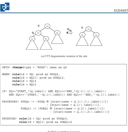
Figure 6: AWIPPOGrule for downsizing adaptation: sequence delete in sequence construct.
4.2 Adaptation Rules
High-level rewriting rules are used to adapt processes during their enactments. They modify the process flow on the basis of the causal relations between tasks and the policy established within the process management system, e.g., maximizing the number of tasks executed in parallel, or reducing the number of tasks performed in parallel (for example, by saving resources), or
other policies. In [De 07], a complete set of rewriting rules for adaptation has been defined. By
following the categorization proposed in [EM97], rules are classified in:(i) downsizing, reducing
the set of traces (i.e. possible executions of tasks according to the process control flow) in the
new adapted process; and(ii) upsizing, extending the set of traces with respect to the old process.
Rules consume/produce special resources taken/put from/into arule resource pool (rrp) by
the process management system when change events take place. These resources represent rules
>>
Q2 Q1
Riss
>>
QN Q1
Q2 >>
Q Q
Q’1 >>
Q2 Q1
Riss
>>
QN Q1
Q2 >> >>
Q2 Q1
>>
Q2 Q1
Riss
>>
QN Q1
Q2 >>
>>
QN Q1
Q2 >>
Q Q
Q’1
(a) CTT diagrammatic notation of the rule
GETS: change(type = “RISS”; name as Q; new as N)
WHEN: rule(id = SQ; prod as PDSQ), rule(id = EQ1; prod as PDEQ1)
IF: SQ == “START_”+Q.label() AND EQ1 == “END_””+Q.1().label()
PROCESSES: PDSQc := (PDSQ - {start(name = Q.1().label())}) ⊕ {start(name = N.label())}, WSQ’1 := {start(name = N.label())},
PDSQ’1 := {start(name = Q.1().label())}, PDEQ’1 := {start(name = Q.2().label())}, WEQ’1 := {completed(name = N.2().label())},
PDEQ1c := (PDEQ1 - {start(name = Q.2().label())}) ⊕{start(name = N.2().label())} SQ’1 := “START_” + N.label(), EQ’1 := “END_”+N.label()
PRODUCES: rule(id = SQ; prod as PDSQc),
rule(id = SQ’1; when as WSQ’1; prod as PDSQ’1), rule(id = EQ1; prod as PDEQ1c),
rule(id = EQ’1; when as WEQ’1; prod as PDEQ’1)
(b) Rule inWIPPOGlanguage
Figure 7: AWIPPOGrule for upsizing adaptation: sequence insertion in sequence construct.
is produced (i.e., the change event takes place), some rules are removed from rrp and new
ones are added into it, yielding a new rule resource poolrrp0 representing the adapted process.
Specifically, the high-level rewriting system manages (rewrites) multi-sets which are composed
by the following elements (resources) expressed inWIPPOG. As these are resources, they have
identifier attributes, which we will omit when not needed.
• rule(id, when, gets, if, proc, prod, outs)is a resource for aWIPPOG
rule in the PMR-system realizing the process schema P. The attribute idrefers to the
identifier associated with the rule, whereas the other attributes specify each component of the corresponding rule;
• change(id, type, name, new)is a resource for a change event (described by its
type) involving the rule (the part of the process) named byname. It represents the event
which starts process adaptation. The attributenew describes the possibly empty set of
rules (the new sub-process) to be added.
PMR-systemPMRS=hRP,{INIT,start(name = ‘‘P’’)}iand a setADAPTof rules for
adapta-tion, is the pairHPMRS=hADAPT,RPi. A sequence of direct derivationsHigh∆=RP=a⇒1 R
P1 a2
=⇒ · · · an
=⇒RPn, is aderivationof the HPMR-systemHPMRS, also denoted byRP=⇒∗RPn.
The languageL(HPMRS)generated by the HPMR-systemHPMRSis the set of all multi-sets
RPn such thatRP=⇒∗R
Pn.
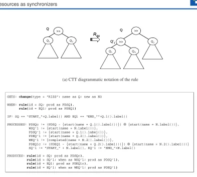
Figures6and7show examples of high-level downsizing and upsizing rules, respectively. In
the upper side of the Figures, a simplified version of the CTT diagrammatic notation [MPS02],
is used to indicate the synchronization constraint imposed on the process. The operator “>>”
denotes sequentiality and indicates that the tasks in the right subtree can be executed only after those in the left subtree have been completed. Leaves represent elementary tasks. Specifically,
the rule with typeRdssin Figure6(Sequence Delete in Sequence Construct) deletes a sequential
sub-process (identified by the label obtained through the methodlabel()of the object
con-tained in the variable Q) from a sequence construct. In detail: theGETScomponent contains the
change requestresource needed to enable the rule, whereas theWHENcomponent identifies the
local rules to be changed / removed fromrrp. The rules are identified by concatenation of the
strings “START ” or “END ” with unique labels associated to each node belonging to process
tree. The methods1()and2()return the left and right child, resp., of a subtree Q. On the other
hand, thePROCESSEScomponent contains the computational activities to be executed with the
transition: in particular, some synch resources5 are removed and added from thePRODUCES
components of the rules involved during the adaptation. Finally, thePRODUCES component
produces the new rule resources representing the adapted process, which is the result of applying the high-level rule.
5 Applying the Model
In this section we apply the rewriting machinery to the scenario described in Section 1. We
recall that restructuring is needed when the condition of the OR-split construct present in the
process schema becomestrue. In fact, in this case, the process instance requires the execution
of another instance of the task “Take Pictures”, and, since there is only one PDA (resource) equipped with photo-camera in the team (i.e., the PDA of the team member 3), one of the two instances has to be postponed with respect to the other.
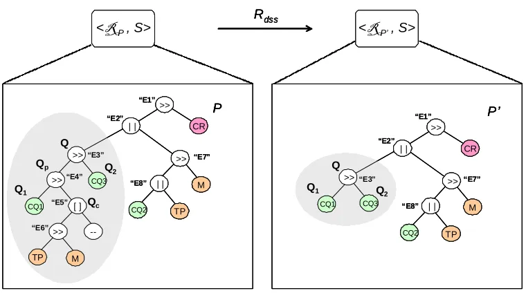
The left-hand side of Figure8shows the process of Figure1(a) as a binary tree in the
simpli-fied CTT notation. A tree node with value “–” represents the null operation in the false branch of
the OR-split construct. When the process management system produces aresource unavailability
eventfor team member 3 (a change resource is produced), the inference engine module changes
the PMR-systemhRP,Siinto the new one <RP00,S>, by(i)removing tasks “Take Pictures”
and “Matching” within the OR-Split construct in sequence the tasks “Compile Questionnaire 1”
and “Compile Questionnaire 3”, and(ii)adds these tasks before “Compile Report”.
This mechanism can exploit a layered organization analogous to that proposed in [PHE+07],
so that amobility layercan signal disconnection events for theworkflow layerto rearrange the
attribution of tasks in thework layer. Specifically, the process engine consumes two change
<R P’, S> Rdss
<R P , S>
P P’ >> | | >> M | | CR TP CQ2 >> >> CQ1 CQ3 TP [ ] M -->> Q Qp Q1 Qc Q2 >> | | >> M | | CR TP CQ2 >> CQ1 CQ3 Q
Q1 Q2
“E1” “E2” “E3” “E7” “E8” “E4” “E5” “E6” “E3” “E2” “E1” “E7” “E8” <R P’, S> Rdss
<R P , S>
P P’ >> | | >> M | | CR TP CQ2 >> >> CQ1 CQ3 TP [ ] M -->> Q Qp Q1 Qc Q2 >> | | >> M | | CR TP CQ2 >> CQ1 CQ3 Q
Q1 Q2
<R P’, S> Rdss
<R P , S>
P P’ >> | | >> M | | CR TP CQ2 >> >> CQ1 CQ3 TP [ ] M -->> Q Qp Q1 Qc Q2 >> | | >> M | | CR TP CQ2 >> >> CQ1 CQ3 TP [ ] M -->> Q Qp Q1 Qc Q2 >> | | >> M | | CR TP CQ2 >> CQ1 CQ3 Q
Q1 Q2
>> | | >> M | | CR TP CQ2 >> CQ1 CQ3 Q
Q1 Q2
“E1” “E2” “E3” “E7” “E8” “E4” “E5” “E6” “E3” “E2” “E1” “E7” “E8”
Figure 8: Process Transformation 1: Sequence Delete in Sequence Construct.
requestresources produced by a specific predictive module which alerts about resource
unavail-ability (these resources are put in theGETScomponent of the WM running on the device of the
team leader): firstly, a change requestresource change(id = “ce1”, type = “RDSS”; name =
“E4”;)is consumed, where “RDSS”is the rule type to be applied, and “E4” denotes the name of
the rule which is going to be changed in the PMR-system; secondly, achange requestresource
change(id = “ce2”, type = “RISS”; name = “E1”; new = “E4”)is taken from the change re-source pool. “E1” is the name of the rule to be changed, and “E4” is the name of rule to be added in the PMR-system together with all rules representing the sub-tree with root node “E4”.
In consuming the two change resources, the adaptive process engine applies the relative rewrit-ing rules belongrewrit-ing to the high-level rewritrewrit-ing system. The matches to the local rules are
con-strained by the values of the attributes in the change request events. Specifically, in the first
case, it applies ruleRdss(Sequence Delete in Sequence Construct), and in the second case rule
Riss(Sequence Insertion in Sequence Construct). In particular, in both cases the high-level rules
consume rule resources associated to specific branches of the process schema and produce new ones according to the adopted rewriting rule.
The rule resource pool after the application of the two adaptation rules Rdss and Riss is as
follows6:
RP=RP0 t
{ rule(id = ‘‘START E3’’; ...),
rule(id = ‘‘START CQ1’’; ...), rule(id = ‘‘START E4’’; ...), rule(id = ‘‘END E4’’; ...)
6 In describing the resources associated to rules, we have reported in bold or omitted part of them (gets,if,
}
RP0 =RP0 t
{ rule(id = ‘‘START E3’’;
when = start(name = ‘‘E3’’);
gets = msgs for E3;
if = conds for E3;
proc = procs for E3;
prod = start(name = ‘‘CQ1’’);
outs = msgs from E3),
rule(id = ‘‘START CQ1’’; ... ;
prod = start(name = ‘‘CQ3’’); ...)
}
RP0 =RP
1 t
{ rule(id = ‘‘START E1’’; ...),
rule(id = ‘‘END E4’’; ...) rule(id = ‘‘END E2’’; ...) rule(id = ‘‘START E4’’; ...)
}
RP00 =RP1 t
{ rule(id = ‘‘START E1’’;
when = start(name = ‘‘E1’’);
gets = msgs for E1;
if = conds for E1;
proc = procs for E1;
prod = start(name = ‘‘E4’’);
outs = msgs from E1),
rule(id =‘‘END E4’’; ...;
prod = start(name = ‘‘CR’’); ...) rule(id =‘‘START E4’’; ...;
prod = start(name = ‘‘E2’’); ...) rule(id =‘‘END E2’’; ...;
prod = start(name = ‘‘E5’’); ...)
}
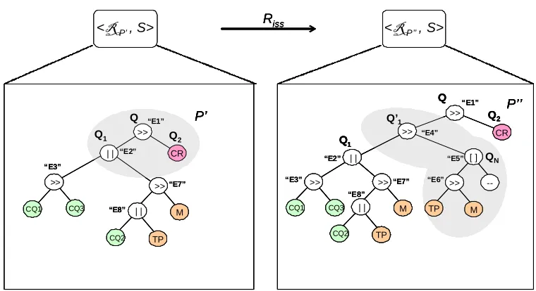
The application of both rules yields the new processes depicted in the right-hand side of
Fig-ure 8 (note the new subtree with root node “>>” and children “CQ1” and “CQ2”) and
Fig-ure9. The PMR-system (<RP,S>) defining the process before the translations is changed into
(<RP00,S>) in which someWIPPOGrules are altered as required byRdssandRiss. Note that, in
<R P’’, S> Riss
<R P’, S>
P’ >> | | >> M | | CR TP CQ2 >> CQ1 CQ3 Q
Q1 Q2
P’’ >> CR >> | | >> M | | TP CQ2 >>
CQ1 CQ3 TP
[ ] -->> M Q Q1 Q2 Q’1 QN “E1” “E2” “E3” “E7” “E8” “E1” “E4” “E2” “E3” “E7” “E8” “E5” “E6” <R P’’, S> Riss
<R P’, S>
P’ >> | | >> M | | CR TP CQ2 >> CQ1 CQ3 Q
Q1 Q2
P’’ >> CR >> | | >> M | | TP CQ2 >>
CQ1 CQ3 TP
[ ] -->> M Q Q1 Q2 Q’1 QN <R P’’, S>
Riss <R P’, S>
P’ >> | | >> M | | CR TP CQ2 >> CQ1 CQ3 Q
Q1 Q2
P’ >> | | >> M | | CR TP CQ2 >> CQ1 CQ3 Q
Q1 Q2
P’’ >> CR >> | | >> M | | TP CQ2 >>
CQ1 CQ3 TP
[ ] -->> M Q Q1 Q2 Q’1 QN P’’ >> CR >> | | >> M | | TP CQ2 >> CQ1 CQ3 >> | | >> M | | TP CQ2 >>
CQ1 CQ3 TP
[ ] -->> M TP [ ] -->> M Q Q1 Q2 Q’1 QN “E1” “E2” “E3” “E7” “E8” “E1” “E4” “E2” “E3” “E7” “E8” “E5” “E6”
Figure 9: Process Transformation 2: Sequence Insertion in Sequence Construct.
6 Related Work
The adaptation of processes to possible exceptional cases or to changes in management poli-cies has been soon recognised as a necessity for practical uses of process management systems [EKR95, VA97, BCC+99]. Solutions to the related problem of dynamic change i.e., how to
transform the process without suspending all its instances or waiting for all instances to have come to conclusion, with the possibility of creating inconsistent states of process instances have
been studied in formal frameworks, typically defined by Petri nets, such as: WF-nets [AWW03],
Flow Nets [EK95], and MILANO nets [AM00] (i.e. marked, acyclic Free-Choice Petri Nets).
Moreover, adaptation of single process instances becomes necessary when exceptional situa-tions occur or the structure of a process dynamically evolves. When the needed changes and their scope for process evolution are known at design time, adaptations can be pre-planned and
auto-mated [HJKW96,LC93,MGR04]. In contrast ad-hoc changes have to be applied as response to
unforeseen exceptions [RD98].
Ad-hoc change in process management is handled in the ADEPT, Breeze, WASA2, e-Flow
systems [RD98, SMO00, Wes01, CS01], in which the issue of manually modifying process
schemas and then automatically migrating active process instances to the new schema is
ad-dressed, and the AGENTWORK one [MGR04], which is one of the few examples of process
management system in which adaption is not manual, but automatic and pre-planned, on the basis of a rule-base approach based on ECA (Event/Condition/Action) model to automatically detect logical failures and to determine necessary process changes. The previous approaches are tar-geted to infrastructure-based workflows, in which modifications of the schemas are less frequent,
but the number of running instances is very high, so that they are less suited toMANETcontext,
in which adaptation concerns a single instance of workflow, under constant possible need for
Several algebraic approaches to rewriting supporting flexibility and adaptability for Petri net
classes can be found in the literature (see [Hof06] for a survey). The recent proposal of Algebraic
Higher-Order (AHO) Nets [Hof06] is a novel modeling technique combining the advantages
of the well-researched classes of Coloured Petri Nets [Jen92] and Algebraic High-Level Nets
[EHP+02]. AHO-Nets can be seen as a formal approach for Higher-Order Object Nets [Han97],
which are well-established for modeling process schemas. Specifically, high-level net classes are obtained by combining Petri nets with an appropriate data type part. While the net structure of AHO-Nets is graphically modeled by Petri nets, the concept of higher-order partial algebras turned out to be well-suited data type part for AHO-Nets. The combination of these techniques is achieved by the inscription of net elements with terms over the given data type part. All these algebraic approaches are very suitable when used at the design-time (they are useful during a design-time reasoning phase on probable deadlock situations of the system), but they are not adequate for modeling run-time aspects, such as unforeseen events during the process execution. The approach proposed in this work is situated in the framework of the algebraic approach to rewriting, which has been widely used for term rewriting, graph transformations, higher-order
structures, and put to work in several contexts (for surveys, see [CMR+97,EEKR99]). In
par-ticular, the DPO approach has been applied to the description of several types of process, to describe both the behaviour of systems and changes in their structures. For example, Distributed Graph Transformations exploit a hierarchical view of distributed systems, where high-level “net-work” graphs define the overall architecture of a distributed system, while low-level
“specifi-cation” ones refer to the specific implementation of local systems [TFKV99]. The approach is
similar to that presented in this work; there, rules act at two levels, i.e., a modification of the network graph must be accompanied by a consequent transformation in the associated specifica-tion graphs. Moreover, low-level graphs must agree on transformaspecifica-tions of interface nodes i.e., nodes which represent common objects or relations. This approach has been applied to manage
dynamic change in distributed databases in [TGM98].
7 Conclusion and Future Work
We have presented a rule-based formalism for modelling the complex processes involved in the
activity of a team cooperating over aMANETand their adaptations. The formalism, expressed in
terms of multi-set rewriting, supports a resource-centered view in which both data-dependencies between tasks and plan-dependent ordering of tasks are expressed as production and consump-tion of resources of different types. Moreover, rules themselves are seen as resources, so that they are prone to the same rewriting process, in order to redefine process schemas.
Generally, process schemas are modeled through Petri nets with an initial marking, called place/transition (P/T) systems, which lend themselves to simple visualizations of processes and their executions. With respect to the formalism proposed in this work, it is possible to asso-ciate a non-hierarchical coloured Petri-net (CP-net) for each PMR-system representing a process
schema. Thus, by the P/T-net theory (Theorem 2.16 in [Jen92]), for each non-hierarchical
CP-net, it is possible to construct an equivalent P/T-CP-net, i.e., a P/T net which has exactly the same
behaviour as the non-hierarchical CP-net. In [De 07] a procedure to construct a non-hierarchical
Furthermore, we will consider organizational issues such as assignment of tasks to team mem-bers within the proposed framework, and a thorough study will be done to relate this formalism
to the general framework of [BRMH06], based on Algebraic Higher-Order Nets (AHO-Nets)
[Hof06], which is an high-level net class combining Petri nets and a suitable higher-order data type part. Differently from the multi-set rewriting model presented in this work, the AHO-Nets framework provides an implicit distinction between the four phases of the system for pro-cess adaptation – i.e., propro-cess execution, propro-cess suspending, propro-cess changing, and propro-cess re-execution – throughout the machinery of the Petri net, while our approach explicitly distin-guishes between these activities.
An adaptive process management system forMANETs is being implemented, specifically
tar-geted to emergency teams equipped with PDAs and laptops (i.e., teams with not too powerful
devices). Such a system, referred to asMOBIDIS, is partly realized7, and will be completed and
then validated in the context of the research project IST FP6WORKPAD8. This prototype will
be used also for validating the algebraic approach presented in this work.
Finally, transformations betweenworkflow patterns9can be studied, in which high-level rules
will represent possible changes between them.
References
[AM00] A. Agostini, G. D. Michelis. A light workflow management system using simple
process models.IJCC9(34):335–363, 2000.
[AWW03] W. van der Aalst, M. Weske, G. Wirtz. Advanced topics in workflow management:
Issues, requirements, and solutions.IJIDP7:49–77, 2003.
[AZ03] D. Agrawal, Q. Zeng. Introduction to wireless and mobile systems. Thomson
Brooks/Cole, 2003.
[BCC+99] L. Baresi, F. Casati, S. Castano, I. Mirbel, B. Pernici. WIDE workflow development
methodology. InProc. WACC. Pp. 19–28. 1999.
[BDD+04] P. Bottoni, M. De Marsico, P. Di Tommaso, S. Levialdi, D. Ventriglia. Definition
of visual processes in a language for expressing transitions.JVLC 15(3):211–242,
2004.
[BN98] F. Baader, T. Nipkow. Term rewriting and all that. Cambridge University Press,
1998.
[BRMH06] P. Bottoni, F. D. Rosa, M. Mecella, K. Hoffmann. Applying algebraic approaches for
modeling workflows and their transformations in mobile networks.IJMIS2(1):51–
76, 2006.
7 http://www.dis.uniroma1.it/pub/mecella/projects/MobiDIS/ 8 www.workpad-project.eu
[CMR+97] A. Corradini, U. Montanari, F. Rossi, H. Ehrig, R. Heckel, M. L¨owe. Algebraic
approaches to graph transformation; basic concepts and double pushout approach. In G. Rozenberg (eds.) Handbook of Graph Grammars and Computing by Graph Transformation: Foundations1, 1997.
[CS01] F. Casati, M. Shan. Dynamic and Adaptive Composition ofe-Services.IS26(3):143–
163, 2001.
[De 07] F. De Rosa. Adaptive process management in mobile and dinamic scenarios. PhD
thesis, SAPIENZA - Universit`a di Roma, Department of Computer Science, Italy, 2007.
[EEKR99] H. Ehrig, G. Engels, H. Kreowski, G. Rozenberg.Handbook of Graph Grammars
and Computing by Graph Transformation: Applications, Languages and Tools. Vol-ume 2. World Scientific, 1999.
[EHP+02] H. Ehrig, K. Hoffmann, J. Padberg, P. Baldan, R. Heckel. High-Level Net Processes.
InFormal and Natural Computing. LNCS 2300, pp. 191–219. 2002.
[EK95] C. Ellis, K. Keddara. A workflow change is a workflow. InProc. BPM. Pp. 201–217.
1995.
[EKR95] C. Ellis, K. Keddara, G. Rozenberg. Dynamic change within workflow systems. In
Proc. COOCS. Pp. 10–21. 1995.
[EM97] C. Ellis, C. Maltzahn. The Chautauqua workflow system. InProc. ICSS. Pp. 427–
428. 1997.
[GPS98] M. Große-Rhode, F. P. Presicce, M. Simeoni. Spatial and temporal refinement of
typed graph transformation systems. InProc. MFCS’98. LNCS 1450, pp. 553–561.
1998.
[Han97] Y. Han.Software Infrastructure for Configurable Workflow System - A Model-Driven
Approach Based on Higher-Order Nets and CORBA. PhD thesis, Technische Uni-versit¨at Berlin, 1997.
[HJKW96] P. Heimann, G. Joeris, C. Krapp, B. Westfechtel. DYNAMITE: dynamic task nets
for software process management. InProc. 18th ICSE. Pp. 331–341. 1996.
[Hof06] K. Hoffmann.Formal Approach and Applications of Algebraic Higher Order Nets.
PhD thesis, Technical University Berlin, 2006.
[Jen92] J. Jensen.Coloured Petri Nets. Basic Concepts, Analysis Methods and Practical Use.
Springer-Verlag, 1992.
[LC93] C. Liu, R. Conradi. Automatic replanning of task networks for process model
[MGR04] R. M¨uller, U. Greiner, E. Rahm. AGENTWORK: a workflow-system supporting
rule-based workflow adaptation.DKE51(2):223–256, 2004.
[MPS02] G. Mori, F. Patern`o, C. Santoro. CTTE: Support for Developing and Analyzing Task
Models for Interactive System Design.IEEE TSE28(8):797–813, 2002.
[Pat99] N. Paton (ed.).Active rules in database systems. Springer, 1999.
[PHE+07] J. Padberg, K. Hoffmann, H. Ehrig, T. Modica, E. Biermann, C. Ermel. Maintaining
Consistency in Layered Architectures of Mobile Ad-Hoc Networks. InProc. FASE
2007. LNCS 4422, pp. 383–397. Springer, 2007.
[RD98] M. Reichert, P. Dadam. ADEPTf lexsupporting dynamic changes of workflows
with-out losing control.JIIS10:93–129, 1998.
[RR06] S. Rinderle, M. Reichert. Data-Driven process control and exception handling in
process management systems. InProc. CAISE 2006. Pp. 273–287. 2006.
[RRD04] S. Rinderle, M. Reichert, P. Dadam. Correctness criteria for dynamic changes in
workflow systems - a survey.DKE50:9–34, 2004.
[SMO00] S. Sadiq, O. Marjanovic, M. Orlowska. Managing change and time in dynamic
work-flow processes.IJCIS9(1-2):93–116, 2000.
[SSO01] S. Sadiq, W. Sadiq, M. Orlowska. Pockets of flexibility in workflow specification. In
Proc. ER 2001. LNCS 2224, pp. 513–526. 2001.
[TFKV99] G. Taentzer, I. Fischer, M. Koch, V. Volle. Visual design of distributed systems by
graph transformation. In Ehrig et al. (eds.), Handbook of Graph Grammars and
Computing by Graph Transformation, vol. 3: Concurrency, Parallelism, and Dis-tribution. World Scientific, 1999.
[TGM98] G. Taentzer, M. Goedicke, T. Meyer. Dynamic change management by distributed
graph transformation: Towards configurable distributed systems. InProc. TAGT’98.
LNCS 1764, pp. 179–193. 1998.
[VA97] M. Voorhoeve, W. van der Aalst. Ad-hoc workflow: problems and solutions. InProc.
8th DEXA. Pp. 36–37. 1997.
[Wes01] M. Weske. Formal foundation and conceptual design of dynamic adaptations in a
workflow management system. InProc. HICSS’01. Pp. 7051–7052. 2001.
[WMC06] WMC. Workflow Management Coalition Terminology & Glossary. Technical