421
SECURED COMMUNICATION USING SPREAD
SPECTRUM TECHNIQUES
Dr.C.Kumar Charliepaul
1Principal
A.S.L Pauls College of Engg & Tech, Coimbatore .
[email protected]
ABSTRACT:
The objective of this work is to use the concept of secured communication using spread spectrum techniques(i.e..) to generate pseudo random noise sequence combines with the input digital data and this modified signal is to be modulated by BPSK technique in order to reduce the jamming of communication. The hacking of information is not possible unless otherwise the pseudo random sequence is known.To implement this concept ,a pseudo random sequence generator is required to produce the pseudo noise and a modulator is used in order to provide lossless communication.The receiver demodulates the original digital data by using same pseudo random sequence.Thus the whole system will be simulated and the performance will be analysed. KEYWORDS:
Data signal, Spread spectrum-SS, Pseudo-noise PN generator, Direct Sequence DS-SS and Frequency Hopping FH-SS system, Synchronization, CDMA technique.
1. INTRODUCTION:
Spread Spectrum communication system holds a promising future for heightened secured communication.This article presents a spread spectrum (i.e..) transmission of signal which occupies bandwidth much in excess of minimum necessary to send the information.The band spread is accomplished by utilising a code which is independent of data and synchronised reception with the code at the receiver is used for de-spreading and data recovery.The code is generated by pseudo random sequence generator which is combined with the input digital data to spread the signal in random manner.The system consists of two techniques -Direct sequence spread spectrum and Frequency hopping spread spectrum. A Matlab Simulink is developed to measure the Signal to Noise ratio and Bit Error Rate.Frequency hopping spread spectrum(FHSS) gives high performance than Direct sequence spread spectrum and this FHSS technique is implemented in hardware.
The SS Communications are widely used today for Military, Industrial, Avionics, Scientific, and Civil uses. It is secure means of communication, due to unknown random codes.. SS communication has low power spectral density as the signal is spread over a large frequency-band which does not cause disturbance to other communication systems. As the signal bandwidth spreads, the interference operation also gets limited as the spreaded bandwidth allows more data signal to transmit
at a particular time period. Application of SS implies the multipath effects as spreaded bandwidth creates many paths for many data signal to transmit at any arbitary time in random order.
In this paper an attempt has been made to proposed and analyzed the spread spectrum along with the performance analysis of pseudo random code generators implemented in Spread spectrum communication system. Applicability of pseudo random generators has been studied by evaluating
the autocorrelation, cross-correlation performance and the bit error rate for codes of different length of the communication system. Further two main spread-spectrum techniques, types offrequency-hopping systems, synchronization between PN sequences has also been described with its computer simulations for performance analysis of spread spectrum system.
2. PSEUDO NOISE SEQUENCE:
A PseudoNoise or Pseudorandomsequence is a binary sequence with an autocorrelation that resembles, over a period, theautocorrelation of a random binary sequence. It is generatedusing a Shift Register, and a Combinational Logic circuit as itsfeedback. The Logic Circuit determines the PN words.Due to the usage of the PN code, the spread spectrumtechnique has the ability to discriminate interference signalsand detect the received signal by matching received PN codewith the local PN code and measuring the number of chips ofthe code delay between the signal being transmitted andreceived, and thus determine uniquely the
range from thetransmitter to the receiver without
ambiguity.Consequently the spread spectrum technique has its advantagein that its phase is easily resolved.There are three basic properties that can be applied to aperiodic binary sequence (PN sequence) as a test of theappearance of randomness, they are: 1. Balance Property: Good balance requires that in eachperiod of the sequence, the number of binary Ones differsfrom the number of binary Zeros by at most one digit.
2. Run Property: A run is defined as: sequence of a singletype of binary digits. The appearance of the alternate digit in asequence starts a new run. It is desirable that about one halfthe runs of each type is of length 1, about one fourth of length2, one eighth is of length 3, and so on.
3. Correlation Property: If a period of the sequence iscompared term by term with any cyclic shift of itself, it is bestif the number of agreements differs from the number of disagreements.
422 3. TYPES OF SPREAD SPECTRUM TECHNIQUES:
There are many types of spread spectrum techniques as: Direct sequence (DS), frequency hopping, time hopping and hybrid system. Direct sequence contrasts with the other spread spectrum process, in which a broad slice of the bandwidth spectrum is divided into many possible frequencies. Frequency-hopping devices use less power and are cheaper, but the performance of DS-SS systems is usually better and more.Thus, in this paper we will deal only with direct sequence and frequency hopping method.
3.1. DIRECT SEQUENCE SPREAD SPECTRUM:
In Direct Sequence-Spread Spectrum the base-band waveform is XOR by the PN sequence in order to spread the signal. After spreading, the signal is modulated and transmitted.
Fig1. DSSS block diagram
Direct Sequence-Spread Spectrum the baseband that arise when using RF signals for distance ranging system waveform is XOR by the PN sequence in order to spread the will be discussed and it will be shown how the spread signal. After spreading, the signal is modulated and spectrum can solve them. Direct sequence (Fig 1) contrasts with the other spread spectrum process, in which a broad slice of the bandwidth spectrum is divided into many possible broadcast frequencies.
Fig 2.DSSSTransmitterblockdiagram
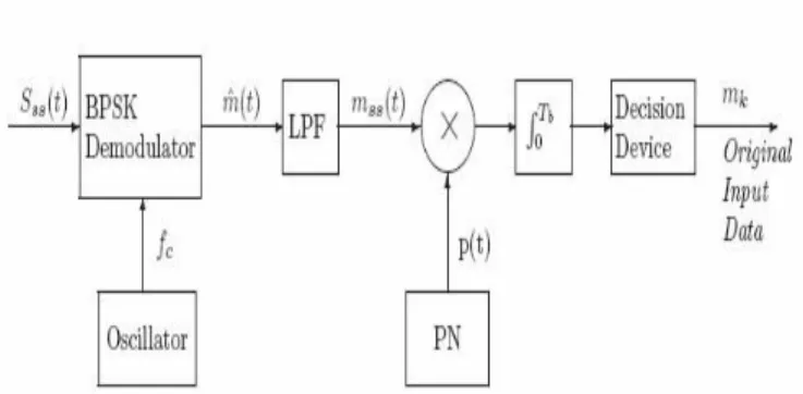
Fig 3.DSSS Receiver block diagram
The spreading waveform is controlled by a pseudo-Noise (PN) sequence, which is a binary random sequence. This PN is then multiplied with the original base-band signal, which has a lower frequency, which yields a spread waveform that has noise-like properties. In the receiver, the opposite happens, when the pass-band signal is first demodulated, and then de-spreaded using the same PN waveform. An important factorhere is the synchronization between the two generated sequences
3.2 FREQUENCY HOPPING SPREAD SPECTRUM:
FH is the type of SS in which the carrier hops randomly form one frequency to another. A common modulation format for FH system is of M-ary frequency shift keying (MFSK). The combination of these two techniques is referred to simply as FH/MFSK. In this type of SS , the use of PN sequence is to modulate a phase shift keyed signal to achieve instantaneous spreading of the transmission bandwidth. The ability of such a system to combat the effects of jammers is determined by the processing gain of the system, which is a function of the PN sequence period. Two basic characterizations of frequency
hopping:-a) Slow Frequency Hopping, in which the symbol rate Rs
of the MFSK signal is an integer multiple of the hop rate Rh. That is several symbols are transmitted
on each frequency hop.
b) Fast Frequency Hopping, in which the hop rate Rh
is an integer multiple of the MFSK symbol rate Rs.
That is, the carrier frequency will change or hop several times during the transmission of one symbol.
3.2.1.SLOW FREQUENCY HOPPING :
423 synthesizer, which enables the carrier frequency to hop over 2k distinct values. On a single hop, the bandwidth of the transmitted signal is the same as that resulting from the use of conventional MFSK with M=2k orthogonal signals. However, for a complete range of 2k frequency hops, the transmitted FH/MFSK signal occupies a much larger bandwidth.
The frequency hopping is first removed by mixing (down converting) the received signal with the output of a local frequency synthesizer that is synchronously controlled in the same manner as that in the transmitter. The resulting output is then band pass filtered, and processed by a non coherent M-ary FSK detector.
Fig4.Frequency hop spread M-ary frequency shift keying a) transmitter b) receiver
3.2.2 FAST FREQUENCY HOPPING:
A fast FH/MFSK system differs from a slow FH/MFSK system in that there are multiple hops per M-ary symbol. In a fast FH/MFSK system, each hop is a chip [12]-[14]. Fast frequency hopping is used to defeat a smart jammers tactic that involves two functions:- measurements of the spectral content of the transmitted signal, and retuning of the interfering signal to that portion of the frequency band. For data recovery at the receiver, non coherent detection is used. The detection procedure is as
follows:-1. For each FH/MFSK symbol, separate decisions are made on the K frequency hop chips received, and a simple rule based on majority vote is used to make an estimate of the dehopped MFSK symbol. 2. For each FH/MFSK symbol, few functions are
considered as a function of the total signal received over k chips, and the largest one is selected.
4.SYNCHRONIZATION REQUIREMENTS:
The recovery of the information bearing signal requires the receiver’s own copy of the PN sequence to be synchronized with the transmitter’s one. For its proper operation, a SS communication system requires the locally generated PN sequences used in the receiver to despread the received signal to be synchronized to the PN sequence used to spread the transmitted signal in the transmitter
Acquisition and tracking. In acquisition, or coarsesynchronization, the two PN codes are aligned to within a fraction of the chip in as short a time as possible. Once the incoming PN code has been acquired, tracking or fine synchronization, takes place. PN acquisition takes place in two steps:-
1.
First, the received signal is multiplied by a locally generated PN code to produce a measure of correlation between it and the PN code used in the transmitter .2.
Second an appropriate decision rule and search strategy is used to process the measure of correlation so obtained to determine whether the two codes are in synchronism and what to do if they are not.6. Application of SS communication system
Spread spectrum communication can be used for a multiple access techniques like Code Division MultipleAccess
(CDMA) process. It refers to a method to transmit multiple users data simultaneously using coding, ideally orthogonal, to add dimensionality to the transmit space. CDMA technique is combined with direct sequence spread spectrum (DSSS) modulation to yield direct sequence code division multiple access communication.
.
424 Fig5 shows a block diagram of a wireless DS-CDMA system. The unmodulated users data, can be either a serial binary bit stream or a serial multilevel data stream. This data stream is then modulated by a higher bit rate code sequence which increases the bandwidth of the baseband data signal. This baseband spread spectrum signal, is finally modulated with a radio frequency (RF) carrier, before being transmitted into the air (RF channel).
During transmission through the channel signal gets corrupted by the addition of multipath interference, random noise and other interfering signals is then RF demodulated yielding the baseband SS signal.The final baseband demodulation despreads and recovers the original data signal. While transmiting the data the following points need to be considered.
Unique orthogonal code is assigned to each channel
For recover the signal, the receiver needs to know the code used by the transmitter
Fig6
.
CDMA Block Diagram5.SIMULATION RESULT
:
5.1 DSSS TECHNIQUE:
In DSSS technique the digital signal is generated by means of random integer generator. The signal will be in the form ofunipolar which should be converted into bipolar with the help of unipolar to bipolar converter in order to achieve easy multiplication. Pseudo random sequence generator is used to generate the pseudo random sequence.
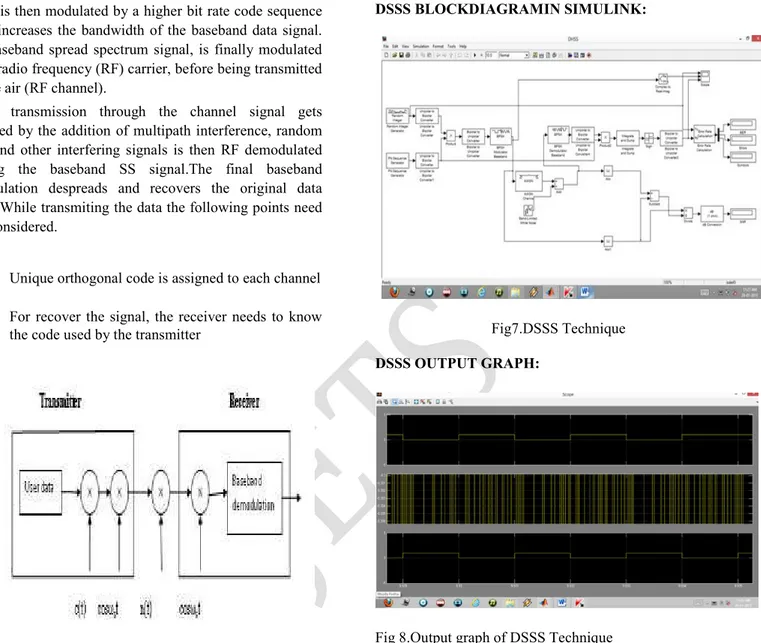
DSSS BLOCKDIAGRAMIN SIMULINK:
Fig7.DSSS Technique
DSSS OUTPUT GRAPH:
Fig 8.Output graph of DSSS Technique
This pseudo random sequence is getting multiplied with the digital input signal. Now the signal becomes noisy. This noise signal is modulated with the help of bpsk modulator. The bpsk modulator is used to modulate digital signal into analog signal.
425 5.2 FHSS TECHNIQUE:
FHSS BLOCK DIAGRAM:
Fig9.FHSS Technique
Bernoulli binary data produces sequence of successive bits which is given to encoder. Hop index is mainly used for synchronization purpose. The output from the encoder is converted into frames and is combined with the Hop index which is then modulated. Band limited noise is added in the AWGN channel. The real part of modulated signal and the noise is calculated. From this Signal to Noise Ratio is calculated. The SNR in FHSS is low when compared with DSSS. The packets are dis-assembled in the receiver side and BER is also calculated.
6.FORMULAE:
Signal to Noise Ratio:
Bit Error Rate:
7. COMPARISON TABLE:
CONCLUSION:
Spread spectrum signals such as DS-SS or FH-SS can tolerate jammers to a large extent but they are still susceptible to jammers due to their low signal strength. It has also been observed that from computer simulations that some system have a less and BER for users.Spread spectrum system provide private and secure communications because signal is ―hidden like noise.It has no interference with other signals in the same band and provides protection against jamming. The analysis of DSSS and FHSS produce the result that proves FHSS is the best method. In FHSS, BER is reduced with the increase of SNR.
REFERENCES:
[1] Bradley P. Badke, ―Global Positioning System Anti-Jamming Techniques‖, Ph.D Dissertation, Arizona State University, 2002.
[2] Raja Iqbal, and J.S Bedi, ―Performance Analysis of Interference Rejection Techniques in Spread Spectrum Communication‖, TENCON ’91, IEEE Region 10 International Conference on EC3-Energy, Computer, Communication and Control Systems, Vol. 3 , Aug. 28-30,1991
[3] Laurence B. Milstein, Interference Rejection Techniques in Spread Spectrum Communications‖, Proceedings of the IEEE, Vol. 76, No. 6, June 1998
[4] A. Haimovich, and A. Vadhri, Rejection of Narrow-Band Interferences in PN Spread Spectrum Systems Using anEigenanalysis Approach‖, IEEE Seventh SP Workshop on Statistical Signal and Array Processing, pp.383-386, 1994.
[5] Robert C. DiPietro,An FFT Based Technique forSuppressing Narrow-Band Interference in PN Spread SpectrumCommunications Systems‖, ICASSP-89‖, Vol. 2, pp.1360 - 1363, May 1989.
[6] R. Abimoussa, R.J. Landry, ―Anti-jamming solution to narrowband CDMA interference problem,‖ Canadian Conference on Electrical and Computer Engineering, Vol.2, pp. 1057-1062, 2000.
[7] Yimin Zhang, Moeness G. Amin, and Alan R. Lindsey, ―Anti-jamming GPS Receivers Based on Bilinear Signal Distributions‖, IEEE Military Communications Conference, Communications for Network-Centric Operations: Creating the Information Force, Vol. 2, pp. 1070-1074, 2001. [8] Werner Krattenthaler and Franz Hlawatsch, Time-Frequency Design and Processing of Signals Via Smoothed Wigner Distributions‖, IEEE Transactions on Signal Processsing, Jan 1993.
[9] Liang Zhao,Moeness G.Amin and lan R. Lindsey,Subspace Projection Techniques for Anti-FM Jamming GPS Receivers‖, Proceedings of the Tenth IEEE Workshop on Statistical Signal and Array Processing, 2000. [10]W.W. Jones, K.R. Jones, ―Narrowband Interference
Suppression Using Filter-Bank Analysis/Synthesis Techniques,‖ IEEE MILCOM Conference, San Diego, California, Paper 38.1.1, 1992 [11]J. Ketchum and J. Proakis, ―Adaptive algorithms for estimating and suppressing narrow-band interference in PN spread spectrum systems,‖ IEEE Trans. Communications, vol. 30, no.5, pp. 913–924, 1982.
[12] L. Milstein and R. Itlis, ―Signal processing for interference rejection in spread spectrum communications,‖ IEEE Signal Processing Magazine, vol. 3, pp. 18–31, April 1986.
[13] M. Amin, ―Interference mitigation in spread spectrum communication systems using time-frequency distributions,‖ IEEE Trans. Signal Processing, vol. 45, no. 1, pp. 90–101, 1997.
[14] M. Amin, S. Ramineni, and A. Lindsey, ―Suppression of
FM interference in DSSS communication systems using projection techniques,‖ in Proceedings of Asilomar Conference on Signal Systems, and Computers, Paci.c Grove, CA, October
426
1999.
[15] M. Amin, C. Wang, and A. Lindsey, ―Optimum interference excision in spread spectrum communications using open loop adaptive .lters,‖ IEEE Trans. Signal Processing, vol. 47, no. 7,pp. 1966–1976, 1999.
[16] S. Barbarossa and A. Scaglione, ―Adaptive time-varying cancellation of wideband interferences in spread-spectrum communications based on time-frequency distributions,‖ IEEE Trans. Signal Processing, vol. 47, no. 4, pp. 957–965, 1999.
[17] Pickholtz R.L., Schilling D.L. and Milstein L.B., ―Theory of spread spectrum communications – a tutorial,‖ IEEE Transactions on Communications, vol. 30, pp. 855–884, May 1982.
[18] Proakis J.G., Digital Communications. New York: McGraw-Hill, 1995. [19] Sarwate D.V.and Pursley M.B.,Crosscorrelation properties of pseudo-random and related sequences,Proceedings of the IEEE, vol. 88, pp. 593– 619, May 1998.
[20] TIA/EIA/IS-95, Mobile station-base station compatibility standard for dual mode wideband spread spectrum cellular system,‖ July 1993. [21] Mottier D. and Castelain D., SINR-based channel pre-compensation for uplink multi-carrier CDMA systems,‖ in Proc. IEEE International Symposium on Personal, Indoor and Mobile Radio Communications (PIMRC 2002), Lisbon, Portugal, Sept. 2002.
[22]Kennedy, M. P.& KolumbanG. [1997] Chaos communications; from theory to implementation," Proc. 1997 European Conf. Circuit Theory and Design, Budapest, pp. 272
Author Biography:-