Abstract— The problem of setting and coordination of
Directional Over-Current Relay (DOCR) is a highly constrained optimization problem that has been solved as a linear programming problem. The calculation of the time dial setting (TDS) and pick up current (IP) setting of the relays is the core of
the coordination. This paper calculates the TDS by choosing one of the available pickup current settings as the predetermined value, in this paper it will be set at 0.5, 1 and 1.5. The LP Dual simplex method is used to determine the optional TDS of the relays in compensated system by series FACTS devices i.e. Thyristor Controlled Series Capacitor (TCSC). A sample system of IEEE 33 bus distribution system is used to demonstrate the feasibility and efficiency of the developed method.
Index Terms— Distribution System; Power System Protection;
LP Dual Simplex Method; DOCRs; TCSC
I. INTRODUCTION
HE primary objective of a protection system is the speedy isolation of the faulted network or the equipment to minimize the impact on other power system components. The protective relaying starts acting after the equipment has begun to get damaged and prevents it from getting damaged any further in order to minimize the danger to the people, reduce stresses on the remaining equipment and above all, to remove the faulted equipment from the system as quickly as possible so as to maintain stability in the system [1]. The over-current relay is widely used in many protection applications throughout power system. When a fault occurs, huge amount of current flows which may damage power system components. Therefore, Over-current relay must isolate the faulted line as soon as possible to protect the system from the faults. The coordination of this protective relay is set up during the process of system design based on the fault current calculation. To clear faults properly within a definite time, each protective relay has to coordinate with other protective relays located at all adjacent buses. Their coordination time is an important factor of the protection system design. Thus, the
L. Bougouffa. Faculty of Technology, Department of Electrical of Engineering, University of El-Oued-Algeria and member in LSP-IE Research Laboratory (e-mail: [email protected]).
A. Chaghi. Faculty of Technology, Department of Electrical of Engineering, University of Batna- Algeria and member in LSP-IE Research Laboratory (e-mail: [email protected]).
overall protection coordination is very complicated [2]. Several methods have been proposed in the past for the coordination of over-current relays. These methods can be classified into two classes which are classical methods and modern based optimization methods [3], [4], [5], [6], [7], [8], [9] Furthermore, due to the complexity of the system, classical methods are time consuming and not optimal. The optimization techniques generally overcome the conventional approach which relays were arranged in a sequence before considered for coordination and due to its advantages, it becomes popular among researchers [10]. Furthermore, optimization techniques eliminate the need to find the set of breakpoints [11]. However, the integration Flexible AC Transmission System (FACTS) in the distribution network increase, the problem of coordinating protective relays becomes more challenging. Recently, several methods have been used to overcome the effect of the controlled series FACTS device, i.e. TCSC and GCSC on optimal coordination of directional over-current relays problem [12]. The authors present a novel strategy for solving the over-current relays coordination problem based on Differential Evolution method. The new idea presented considers the impact of the series compensation degree on the setting of the over-current relays. For the same problem the authors presented in [13] the solution of new setting and coordination problem of DOCR using PSO technique. They formulated the problem as a non linear constrained mono-objective optimization problem. The goal for this optimization is to find an optimal setting of Time Dial Setting (TDS) and Pickup current (Ip) of each relay that minimizes the operating time of overall relays. In [14], the authors investigate the effects of DG integration on the short circuit level in a distribution system in presence of a Thyristor Controlled Series Capacitor (TCSC). In this research work, LP Dual simplex optimization method is proposed to select the optimal values of TDS for three value of Ip and present a solution for the coordination problem between primary and backup relays in presence of D-FACTS devises, but in [15] the authors present the optimization problem to find the TDS’s values for a fixed Ip. In this paper, the algorithms are applied to IEEE 33-bus system in presence of multi-TCSC which is modeled and simulated to verify the efficiency of the proposed algorithm. Moreover, the obtained results when using this algorithm are compared without and with TCSC. The Dual Simplex Method is preferable as the result is better compared
Dual Simplex Method for Optimal Coordination
of DOCR’s in Distribution System with
D-FACTS
Lazhar Bougouffa, Abdelaziz Chaghi
http://innove.org/ijist/ 4 to the nonlinear methods.
II. DIRECTIONAL OVER CURRENT RELYS OPTIMAL COORDINATION PROBLEM
The basic task of the over-current relays is to sense faults on the lines and to rapidly isolate these faults by opening all the current paths. This sensing and switching must occur as fast as possible to minimize damage. However, it should be very selective so no more of the network is removed from service than is necessary. In order to increase reliability, this need has led to the practice of providing both “primary” protections with “backup” protection which should function only if one of the primary devices fails. Over-current relays are classified on the basis of their operation time, in the following three categories: Instantaneous Over-current Relay (IOR), Definite Time Over-current Relay (DTOC) and Inverse Definite Minimum Time (IDMT) Over-current Relay; this relay has an inverse time characteristic. This means that the relay operating time is inversely proportional to the fault current [13].
DOCR coordination problem is a parametric optimization problem, where different constraints have to be considered in solving the objective function [16], [17]. Here the objective function to be minimized is the sum of the operating times of the relays connected to the system, subject to the following constraints. A typical inverse time directional over-current relay has two units, an instantaneous unit (time independent) and an inverse over-current unit (time dependent). The instantaneous unit operates with no intentional time-delay when current is above a predefined threshold value, known as the instantaneous current setting. Time-delay unit is used for current, which is below the instantaneous current setting but exceeds the normal flow due to a fault. This unit operates at the occurrence of a fault with an intentional time-delay [2]. Two settings are associated with the time-delay unit, which are as under
* Time dial setting (TDS)
* Plug setting (PS) (e.g. tap setting)
The pickup value is the minimum value of current for which the relay operates. The time dial setting defines the operating time (T) of the relay for each current value.
The operating time (T) of a DOCR is a non-linear function of the relay settings (time dial settings (TDS) and pickup current (IP) and the fault current (IF) seen by the relay. Thus, relay operating time equation for a DOCR is given by
b a
T TDS
M -1
= (1)
The constants a and b depends on the type of characteristics selected: Standard Inverse (SI), Very Inverse (VI) or Extremely Inverse (EI) [2].
The requirement of selectivity dictates that when a fault occurs, the area isolated by the protective relay must be as small as possible, with only the primary protection relay operating. In addition, the failure possibility of a protective relay must be considered. In this situation, another relay must operate as backup protection. In order to satisfy the requirement of selectivity, the following constraint must be
added:
F1 F1
back-up primary
T −T
CTI
(2)F1 F1
j i
T −T
CTI
(3)Where F1 F1
j i
T −T are the operating times of ith primary relay
TprimaryF1 and jth back-up relay T
back−up F1
respectively.
The Coordination Time Interval (CTI) is the minimum time gap in operation between the primary and its backup relay. CTI depend upon type of relays, speed of the circuit breaker and a safety margin which is usually selected between 0.2 s and 0.5 s [1], [18].
III. THE TCSC CONTROLLER
The TCSC device has been traditionally modeled as a thyristor-controlled reactor in parallel with a fixed capacitor; the reactor and capacitor are represented only by their corresponding reactance. This device proposed in 1986 by Vithayathil with others as a method of "rapid adjustment of network impedance," as shown in Figure.1. [19], [20].
A TCSC is a series-controlled capacitive reactance that can provide continuous control of power on the ac line over a wide range. From the system viewpoint, the principle of variable-series compensation is simply to increase the fundamental-frequency voltage across a fixed capacitor (FC) in a series-compensated line through appropriate variation of the firing angle (α) [12].
In a practical TCSC implementation, several basic compensators may be connected in series to obtain the desired voltage rating and operating characteristics. However, the basic idea behind the TCSC scheme is to provide a continuously variable capacitor by means of partially canceling the effective compensating capacitance by the TCR [21], [22]. Since, the TCR at the fundamental system frequency is a continuously variable reactive impedance, controllable by delay angle α, the steady-state impedance of the TCSC is that of a parallel LC circuit, consisting of a fixed capacitive impedance, Xc, and a variable inductive impedance, XL(α), that is,
L
L TCSC
C ( )
X X
X ( )
( ) X
=
X
C
+ (4)
TCSC has four operation modes: Blocking, Bypass, Capacitive and Inductive mode. The four mode operations are made by firing angle (α) of thyristors.
The TCSC can be installed anywhere in the distribution circuit in order to control the power flow as a function of its capacitive-reactance. Since it is essentially a variable
Fig. 1. Equivalent Circuit of TCSC
L C
T2
T1
reactance, its impedance will be added arithmetically to the system impedance and result in a reduction of the fault currents.
The rated value of TCSC is a function of the reactance where the TCSC is installed and expressed as:
XTotal=Xline+XTCSC (5)
Where
XTCSC = KTCSC . Xline (6) XTotal is the overall line reactance with TCSC installation. XTCSC is the reactance of TCSC and KTCSC is the coefficient which represents the compensation level of TCSC −0.7 KTCSC 0.2). The working range of reactance of TCSC is fixed between -0.7 (capacitive) Xline and 0.2 (inductive)
Xline [23].
IV. APPLICATION OF LP-DUAL SIMPLEX METHOD
Linear programming is one of the various techniques of optimization. It refers to modeling and solving a problem mathematically that involves the economic allocation of limited resources by choosing a particular course of action among various alternatives to achieve the desired accuracy [24]. Dual simplex method is a variant of regular simplex method, developed by Lemke, to solve a LPP. It starts from infeasible solution to the primal. The method works in an iterative manner such that it forces the solution to become feasible as well as optimal at some stage [25].
The algorithm of dual simplex method to solve a maximization problem is given below in Fig. 2 (the minimization problem can easily be converted into maximization problem).
A. Problem formulation
The total time objective function in (7), for N primary relay is minimized, subject to various constraints (2) and (3). These constraints are relay setting constraints and backup-primary relay constraints.
N
i,K i=1
min
T (7)Where N is the number of relays, ti, k is the operating time of the relay Ri, for fault in zone k.
B. Relay characteristics
In this paper the DOCR’s are assumed to have normal IDMT characteristic as comply with the IEC60255-3 standard.
The characteristics of the DOCR are given as a curve of T versus M, where, i.e.
P
I M
I
= (8)
Where M is a Multiple of the Pickup Current. I is the relay current (overload or fault current) and Ip is the pickup current.
From equation (1) one can see that the relation between the operating time T and the multiple pickup current M, is
nonlinear. Since the multiple pickup current of the relays can be predetermined, so for a fixed M, equation (1) becomes linear as follows:
t=a * TDS (9)
Where
0.02
f
p 0.14 a
I -1 I
=
(10)
By substitution from equation (10) in equation (1), the objective function becomes
N
i i
i=1
min
a TDS (11)Equation (11) is optimized using LP-Dual Simplex method [25] subject to the condition that the operation of the backup relays remains properly coordinated.
Start
Form first dual simplex table by taking slack variables as basics and original variables as non-basics Convert all the constraints into equality constraints by
adding slack variables. State the problem in maximization form
(Equi.2 in maximization form)
Convert all the constraints into ≤ type (Equality Constraints) Calculate the fault with and without TCSC Input data of network (Bus-data, Branch data, TCSC
parameters and location, relay data and KTC ratio)
Form cost coefficient (Cj– Σci eij) row
If any element in this row is positive, then the method fails.
2
3 1
If all the elements in this row are negative and all the elements in the column of ‘b’
Identify key row. It is the row having maximum negative value of b
If all the elements in this row are negative and at least one element in the column of ‘b’ is negative
http://innove.org/ijist/ 6 Fig 2. Flowchart of LP-Dual Simplex method
The main advantage of Dual Simplex Method is the artificial variable is not required and consequently, a lot of labor is saved whenever this method is applicable. Since it works towards feasibility and optimality simultaneously, the number of iterations and the number of calculation per iteration in dual simplex method is less as compared to other methods; and hence the Dual Simplex Method is more less time consuming.
V. CASE STUDIES
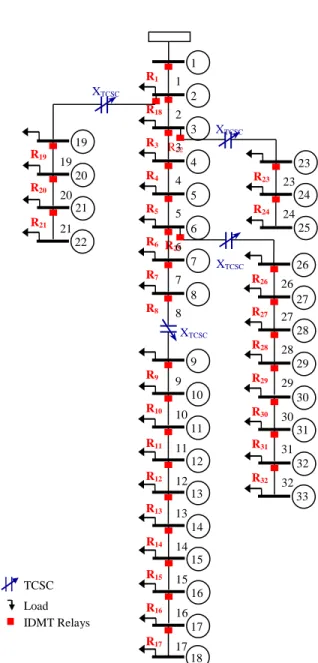
The proposed relay coordination methodology is applied in IEEE 33 bus distribution system of Figure. 3. The information of the network is given in [26]. The main objective is to determine the optimal setting of TDS of relays 32 for a fixed Ip, and under coordination selectivity criteria. All the directional over-current relays have the IEC inverse standard characteristics. The branches 8, 18, 22 and 25 are compensated with the TCSC. For setting the relays in coordinated mode we need load flow, short circuit and protection coordination programs, which are here coded in Matlab.
Fig. 3. IEEE 33-bus test system
VI. RESULTS AND DISCUSSION
In order to illustrate the effects of TCSC insertions in the distribution system on setting of DOCRs, different locations are chosen for installation of TCSC. For this purpose, branches 8 18, 22 and 25 in the most important feeder of the distribution system are selected to compensated. The optimum value of TDS of all relays obtained. In the programs this process was repeated for all possible values of firing angle alpha of TCSC, we selected two angles for each mode. Finally the optimum solution of objective function was selected for various case studies. Using the Dual Simplex Method for three 3
1
If some aij in key row are negative then find the ratio for those columns where aij< 0.
Ratio = (Cj– Σci eij) / (aij)
If all the coefficient values (aij) in key row are non negative then there is no feasible solution for problem
Stop
Decide key column. It is the column having minimum (positive) ratio.
Identify the pivot element (element corresponding to key column and key row) and proceed for formation of next dual simplex table.
Display optimal solution of TDS
2 4
XTCSC
R25
R22 1
R1 1
2
R18 2
3
R3 3
4
R4 4
5
R5 5
6
R6 6
7
R7 7
11
R11 11 9
R9 9
10
R10 10
12
R12 12
14
R14 14 13
R13 13
16
R16 16
17
R17 17 15
R15 15
18 8
R8 8
25 23
R23 23
24
R24 24
33 26
R26 26
27
R27 27
28
R28 28
29
R29 29
30
R30 30
31
R31 31
32
R32 32 19
R19 19
20
R20 20
21
R21 21
22
XTCSC XTCSC XTCSC
TCSC
different values of IP (0.5, 1 and 1.5) and choose the best combination of IP and TDS for optimum setting of relays.
Two scenarios are discussed: no TCSC, the implementation of four TCSC. Various simulations are carried out for uncompensated and multi-TCSC existence. The obtained results are illustrated in tables below.
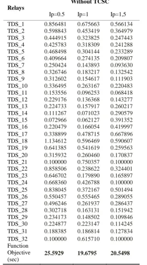
TABLEI
SETTINGS VALUES OF RELAYS'TDSS USING LP-DUAL SIMPLEX METHOD IN DISTRIBUTION SYSTEM WITHOUT TCSC;(IP=0.5,IP=0.5 AND IP=0.5).
Relays
Without TCSC
Ip=0.5 Ip=1 Ip=1,5
TDS_1 0.856481 0.675663 0.566134
TDS_2 0.598843 0.453419 0.364979
TDS_3 0.444915 0.323825 0.247443
TDS_4 0.425783 0.318309 0.241288
TDS_5 0.468498 0.304144 0.233289
TDS_6 0.409664 0.274135 0.209807
TDS_7 0.250424 0.143893 0.093630
TDS_8 0.326746 0.183217 0.132542
TDS_9 0.312602 0.154617 0.111903
TDS_10 0.336495 0.263167 0.220483
TDS_11 0.153556 0.096253 0.068418
TDS_12 0.229176 0.136368 0.143277
TDS_13 0.224733 0.157917 0.260217
TDS_14 0.111267 0.071023 0.290579
TDS_15 0.072966 0.062127 0.391352
TDS_16 0.220479 0.166054 0.419997
TDS_17 0.338899 0.478715 0.667896
TDS_18 1.134612 0.596469 0.590607
TDS_19 0.641385 0.541619 0.259563
TDS_20 0.315932 0.260460 0.170837
TDS_21 0.100000 0.750357 0.100000
TDS_22 0.858506 0.238622 0.324401
TDS_23 0.646702 0.179890 0.165897
TDS_24 0.668360 0.426788 0.100000
TDS_25 0.838045 0.372167 0.501494
TDS_26 0.550457 0.555465 0.289055
TDS_27 0.496246 0.261937 0.286437
TDS_28 0.302718 0.163131 0.151942
TDS_29 0.234173 0.148502 0.109846
TDS_30 0.224877 0.223147 0.114245
TDS_31 0.188385 0.186814 0.127834
TDS_32 0.100000 0.615710 0.100000
Function Objective (sec)
25.5929 19.6795 20.5498
Tables 2 and 3 shows the optimal results of TDSs for
variable values of IP, in presence of TCSC installation in four locations of IEEE 33-bus distribution system. This table includes time of objective function.
TABLEII
SETTINGS VALUES OF RELAYS'TDSS USING LP-DUAL SIMPLEX METHOD IN PRESENCE OF MULTI TCSC(INDUCTIVE MODE) IN FOUR LOCATIONS
From these results we can conclude that the installation of
With TCSC Inductive mode
Ip=0.5 Ip=1 Ip=1.5
Relays α =90° α =135° α =90° α =135° α =90° α =135°
TDS_1 0.947073 0.859045 0.713877 0.906880 0.592502 0.604946
TDS_2 0.686431 0.601321 0.490181 0.675849 0.390254 0.402183
TDS_3 0.543341 0.447699 0.365922 0.578532 0.276801 0.290657
TDS_4 0.568856 0.429831 0.384181 0.716869 0.290036 0.313043
TDS_5 0.576348 0.391043 0.398099 0.872617 0.306956 0.341724
TDS_6 0.579904 0.331332 0.408575 1.087566 0.321046 0.373547
TDS_7 0.443937 0.386974 0.295414 1.659088 0.220908 0.280979
TDS_8 0.443133 0.359384 0.316659 0.327797 0.257698 0.269884
TDS_9 0.378811 0.463192 0.278360 0.539662 0.237382 0.517626
TDS_10 0.348705 0.229725 0.253144 0.369019 0.225568 0.371287
TDS_11 0.155110 0.082337 0.081003 0.273008 0.071510 0.315226
TDS_12 0.208021 0.173676 0.134657 0.113274 0.107475 0.077020
TDS_13 0.223241 0.219143 0.161541 0.174476 0.164274 0.135067
TDS_14 0.115804 0.126924 0.074874 0.114243 0.118632 0.076499
TDS_15 0.075953 0.091827 0.065075 0.187581 0.368492 0.143392
TDS_16 0.261579 0.254894 0.279866 0.069604 0.445950 0.402848
TDS_17 0.526118 0.314277 0.935092 0.100000 0.343585 1.126543
TDS_18 0.351699 0.179485 0.256085 0.142584 0.238310 0.082711
TDS_19 0.240064 0.449386 0.173774 0.311974 0.142387 0.067500
TDS_20 0.242206 1.180544 0.207555 0.160199 0.104427 0.254677
TDS_21 0.100000 1.006137 0.320576 0.097756 0.100000 0.100000
TDS_22 0.915802 0.218322 0.396417 0.276111 0.382737 0.032381
TDS_23 0.718510 0.591770 0.243386 0.387377 0.185576 0.124993
TDS_24 0.722074 0.939585 0.577642 0.498473 0.100000 0.100000
TDS_25 0.474537 0.343860 0.202401 0.132755 0.254038 0.184911
TDS_26 0.250007 0.250018 0.253616 0.271164 0.099742 0.096841
TDS_27 0.346263 0.378621 0.197231 0.228549 0.187159 0.205889
TDS_28 0.309740 0.371641 0.199918 0.274564 0.158787 0.197509
TDS_29 0.245653 0.355408 0.218656 0.409133 0.121654 0.199887
TDS_30 0.248281 0.494761 0.274688 0.180425 0.145124 0.385247
TDS_31 0.276464 0.218847 0.148401 0.133614 0.221167 0.162585
TDS_32 0.100000 0.100000 0.398810 0.230046 0.100000 0.100000
Function Objective (sec)
23.1905 22.0342 18.0116 29.0251 18.0869 19.9024
With TCSC Capacitive mode
Ip=0.5 Ip=1 Ip=1.5
Relays α =136° α =180° α =136° α =180° α =136° α =180°
TDS_1 0.833785 0.869656 0.795068 0.670406 0.615622 0.562146
TDS_2 0.521626 0.611581 0.568286 0.448362 0.412416 0.361157
TDS_3 0.754636 0.459228 0.455361 0.318034 0.302543 0.243003
TDS_4 0.875994 0.446589 0.524133 0.309247 0.332779 0.233916
TDS_5 0.454663 0.413381 0.597714 0.291219 0.371550 0.222147
TDS_6 0.416673 0.361296 0.694206 0.255640 0.418584 0.192983
TDS_7 0.537463 0.202211 0.999311 0.123048 0.332510 0.074380
TDS_8 0.365980 0.220406 0.215941 0.153524 0.149993 0.095327
TDS_9 0.369339 0.199218 0.455580 0.161653 0.390374 0.095022
TDS_10 0.247782 0.185536 0.266921 0.113031 0.214914 0.080341
TDS_11 0.278959 0.178564 0.125912 0.099085 0.082666 0.067769
TDS_12 0.351442 0.211473 0.058184 0.136354 0.131478 0.129410
TDS_13 0.299258 0.219067 0.162745 0.156935 0.255562 0.218216
TDS_14 0.278128 0.111059 0.108495 0.070195 0.352073 0.216095
TDS_15 0.218943 0.072343 0.128261 0.061512 0.299766 0.263123
TDS_16 0.175159 0.167218 0.053686 0.155771 0.187754 0.411859
TDS_17 0.100000 0.256220 0.100000 0.439360 0.100000 0.905193
TDS_18 0.170682 0.814796 0.096295 0.424051 0.086751 0.632965
TDS_19 0.314524 0.425919 0.291608 0.340930 0.083712 0.302360
TDS_20 1.151114 0.256012 0.147827 0.229842 0.250069 0.182456
TDS_21 0.805737 0.100000 0.071883 0.598877 0.100000 0.100000
TDS_22 0.284764 0.861745 0.253339 0.254837 0.068875 0.330583
TDS_23 0.557748 0.637474 0.385084 0.216386 0.116067 0.163716
TDS_24 0.894855 0.658458 0.698029 0.454004 0.100000 0.100000
TDS_25 0.388357 0.350849 0.159308 0.137460 0.197900 0.188210
TDS_26 0.298849 0.252258 0.305617 0.255056 0.116985 0.100570
TDS_27 0.413139 0.347410 0.268716 0.199023 0.217728 0.186806
TDS_28 0.406110 0.310736 0.338563 0.203094 0.216280 0.158109
TDS_29 0.345263 0.244821 0.421838 0.220710 0.191226 0.119405
TDS_30 0.409606 0.244196 0.194254 0.321115 0.302908 0.137594
TDS_31 0.212310 0.308628 0.196847 0.147084 0.154748 0.253879
TDS_32 0.100000 0.100000 0.247677 0.234190 0.100000 0.100000
Function Objective (sec)
http://innove.org/ijist/ 8 TCSC in the distribution system has a great impact of the
coordination and thus a new setting of the relays is required.
TABLEIII
SETTINGS VALUES OF RELAYS'TDSS USING LP-DUAL SIMPLEX METHOD IN PRESENCE OF MULTI TCSC(CAPACITIVE MODE) IN FOUR LOCATIONS; From these results of optimal values of TDS’s we can conclude that the installation of multi TCSC in the distribution system has an impacts on the new settings and coordination of the relays. The results show that the optimal values of TDS’s are decreased in inductive mode as compared to the uncompensated system. In addition, the TDS’s values in capacitive mode of TCSC are increases.
The Dual Simplex Method is more less time consuming is 8.2690 sec for 18 Iteration.
VII. CONCLUSION
The relay coordination scheme was developed through analysis of fault location scenarios at each bus, shown in Figure. 3. The optimal response for a fault at each location was determined. For each fault location, the maximum current observed by each relay was noted. The currents seen at the relays during fault conditions were determined through simulation.
This paper investigates the impact of multi-TCSC on directional over-current relay designed for a radial distribution system. LP-Dual Simplex Method used for optimal coordination of the directional over-current relays in compensated distribution networks. The resultants Time Dial Settings assure a coordinated operation of the relays and guarantee the minimum possible operating times for three value of Ip. The results showed that the proposed LP-Dual Simplex method has capable to finding optimal TDS’s settings with TCSC in LP problem. Moreover, we propose, in the future work, the application optimization techniques to find the optimal coordination of DOCRs in transmission system in the presence of dynamic FACTS.
REFERENCES
[1] P.M. Anderson, “Power System Protection,” McGraw-Hill, New York, 1999.
[2] D. Birla, R.P., Maheshwari, H.O., Gupta, “Time-overcurrent relay coordination: a review,” International Journal Emerging Electrical Power System, vol. 2, 2005.
[3] M. H. Hussaina, *, S. R. A. Rahima , I. Musirinb. “Optimal Overcurrent Relay Coordination: A Review”.Procedia Engineering Volume 53, Pp 332-336, 2013.
[4] Adnan Kakilli, Ugur Kesen, “Examination of Electromechanical Over- Current Relay Characteristics By Using Experimental and ANN Methods” Int. Journal of Engineering Research and Application, vol. 8, Issue 2, Pp 01-06, February 2018.
[5] E. Dehghanpour, H.K. Karegar, R. Kheirollahi, and T. Soleymani. “Optimal Coordination of Directional Overcurrent Relays in Microgrids by Using Cuckoo-Linear Optimization Algorithm and Fault Current Limiter”. IEEE Transactions on Smart Grid, Volume: 9, Pp 1365–1375.
March 2018.
[6] M. Singh, B.K. Panigrahi, A.R. Abhyankar, S. Das. “Optimal coordination of directional over-current relays using informative
differential evolution algorithm” Journal of Computational Science, Volume 5, Issue 2, Pp 269-276, March 2014.
[7] M. Singh, Panigrahi, B.K., Abhyankar, A.R., “Optimal overcurrent relay coordination in distribution system” In Proceedings - International Conference on Energy, Automation and Signal, ICEAS, Pp 822-827. 2011.
[8] M.H. Hussain, I. Musirin, S.R.A. Rahim, A.F. Abidin, “Computational Intelligence Based Technique in Optimal Overcurrent Relay Coordination: A Review”. The International Journal of Engineering And
Science (IJES), Volume 2, Issue 1, Pp 01-09, 2013.
[9] R. Mohammadi, Abyaneh, H.A., Rudsari, H.M., Fathi, S.H., Rastegar, H. “Over-current relays coordination considering the priority of constraints”. IEEE Transactions on Power Delivery, vol. 26, pp. 1927-11938, 2011.
[10] F. Razavi, Abyaneh, H.A., Al-Dabbagh, M., Mohammadi, R., Torkaman, H. “A new comprehensive genetic algorithm method for optimal over-current relays coordination”. Electric Power Systems Research, vol. 78, Pp. 713-720, 2008.
[11] R. Benabid, M. Zellagui, A. Chaghi, and M. Boudour “Optimal Coordination of IDMT Directional Over-current Relays in the Presence of Series Compensation using Differential Evolution Algorithm”.
Proceedings of the 3rd International Conference on Systems and Control,
Algiers, Algeria, October 29-31, 2013
[12] M. Zellagui, and A. Chaghi, “A Comparative Study of GCSC and TCSC Effects on MHO Distance Relay Setting in Algerian Transmission Line”. International Journal of Engineering and Technology (IJET), Vol. 2, No. 2,Pp. 220-228, 2012.
[13] L. Bougouffa, A. Chaghi. “Optimal Coordination of DOCR for Radial Distribution Systems in Presence of TCSC”. International Journal of Power Electronics and Drive System (IJPEDS). Vol.7, No.2, Pp.311~321. June 2016.
[14] L. Bougouffa, A. Chaghi, “Impact of Distributed Generation and Series FACTS Compensator on Directional Over-current Protection Coordination”. International Journal of Hybrid Information Technology (IJHIT) Vol.7, No.4, pp.299-308. 2014.
[15] L. Bougouffa, A. Chaghi. “Optimal Coordination Time Interval for DOCRs in Presence of D-FACTS”. Proceedings of the5th Information
Science and Technology (IEEE CiSt'18), Marrakech, Morocco. October
21–24, 2018.
[16] Prashant P. Bedekar, Sudhir R. Bhide. “Optimum coordination of over-current relay timing using continuous genetic algorithm”. Expert Systems with Applications 38. Pp 11286–11292. 2011.
[17] Zahra M, Mostafa J and Mehdi Gh. “Optimal Coordination Of Distance And Over-Current Relays in Series Compensated Systems Based On MAPSO”. Energy Conversion and Management 56, pp 140–151. 2012. [18] Mazhar E, Robert K. “A novel method for optimal Coordination of
directional over current relays considering their available discrete settings and several operation characteristics”. Electric Power Systems Research 81. Pp 1475–1481, 2011.
[19] Narain G. H and Laszlo G. “Understanding FACTS –Concepts and Technlogy of Flexible AC Transmission Systems”, IEEE Press, 2000. [20] L. Bougouffa, A. Chaghi, “Investigation of TCSC controller effect on
IDMT directional over-current relay”. Procedia - Social and Behavioral Sciences 195, Pp 2421–2429, 2015.
[21] M. Zellagui and A. Chaghi, “Comparing Effects of TCR and TSC on MHO Distance Protection Setting in 400 kV Algerian Transmission Line”. Leonardo Electronic Journal of Practices and Technologies, Issue 21, pp1-14. July-December 2012.
[22] M. Nayeripour and M. Mahdi Mansouri. “Analyze of Real Switching Angle Limits in TCSC on Capacitor and Inductor Values and their Selection Factors”. International Journal of Advanced Science and Technology. Vol. 57, August, 2013.
[23] P. K. Tiwari, Yog Raj Sood. “An Efficient Approach for Optimal Placement of TCSC in Double Auction Power Market”, International Journal of Electronics and Electrical Engineering (IJEEE), pp321-326. 2012.
[24] P. P. Bedekar, S. R. Bhide, and V. S. Kale. “Optimum Coordination of Over-current Relays in Distribution System Using Dual Simplex Method”. 2nd International Conference on Emerging Trends in
[25] A.Kartikeya Sarma and K.Mahammad Rafi. “Optimal Selection of Capacitors for Radial Distribution Systems Using Plant Growth Simulation Algorithm”. International Journal of Advanced Science and Technology. Vol. 30. Pp43-54. May, 2011.
[26] A.Kartikeya Sarma and K.Mahammad Rafi. “Optimal Selection of Capacitors for Radial Distribution Systems Using Plant Growth Simulation Algorithm”. International Journal of Advanced Science and Technology. Vol. 30. Pp43-54. May, 2011.
Dr. Lazhar Bougouffa was born in Batna, Algeria, 1986. He received his MASTER degree in Electrical Engineering from department of Electrical Engineering at University of Batna, Algeria, 2011, and received his Doctorate from Batna University, Algeria 2016. He is currently a lecturer of department of Electrical Engineering at Faculty of Technology El-Oued University, and member LSP-IE research laboratory at faculty of technology-University of Batna. His areas of interest include power system protection, power systems optimization, power quality and FACTS devices.