Resubmitted to the IEEE Transactions on Rehabilitation Engineering, June 19, 2001
The Camera Mouse: Visual Tracking of Body Features to Provide
Computer Access For People with Severe Disabilities
Margrit Betke
∗James Gips and Peter Fleming
Computer Science Department
Computer Science Department
Boston University
Boston College
111 Cummington St
140 Commonwealth Ave
Boston, MA 02215
Chestnut Hill, MA 02467-3808
Abstract
The “Camera Mouse” system has been developed to provide computer access for people with severe disabilities. The system tracks the computer user’s movements with a video camera and translates them into the movements of the mouse pointer on the screen. Body features such as the tip of the user’s nose or finger can be tracked. The visual tracking algorithm is based on cropping an online template of the tracked feature from the current image frame and testing where this template correlates in the subsequent frame. The location of the highest correlation is interpreted as the new location of the feature in the subsequent frame. Various body features are examined for tracking robustness and user convenience. A group of 20 people without disabilities tested the Camera Mouse and quickly learned how to use it to spell out messages or play games. Twelve people with severe cerebral palsy or traumatic brain injury have tried the system, nine of whom have shown success. They interacted with their environment by spelling out messages and exploring the internet.
∗Email: [email protected], http://www.cs.bu.edu/faculty/betke. The work was supported by the NSF equipment grant 9871219
1
Introduction
People who are quadriplegic and nonverbal, for example from cerebral palsy, traumatic brain injury, or stroke, often have great difficulties communicating their desires, thoughts, and needs. They use their limited voluntary motions to communicate with family, friends, and other care providers. Some people can move their heads. Some can blink or wink voluntarily. Some can move their eyes or tongue. Assistive technology devices have been developed to help them use their voluntary movements to control computers. People with disabilities can then communicate through spelling or expression-building programs. This allows users to exhibit their thoughts, emotions, and intellectual potential. Along with the increased ability to communicate, users with severe disabilities can benefit from computer access in many other ways. They can acquire knowledge more actively, partake in increased recreational activities, use the internet, and access computer-controlled technologies such as automated wheelchairs.
Switch-based systems. Assistive technology systems that use switches to control a computer have been used for a considerable period and are still popular [22]. For entering text and other data into a computer, hitting the switch initiates a scan through a matrix of letters, symbols, words, or phrases. Each matrix entry can be selected with a sequence of switch operations. Current research in this area focuses on dynamically adapting matrix row and column scan delays in order to increase the individual user’s text entry rate without complicating the visual display [27]. This is an important issue, since the inability to communicate at an effective rate is a serious barrier for people with disabilities [28].
Infrared systems. People with severe disabilities who retained the ability to rotate their heads have other assistive technology options. For example, there are various commercial mouse alternatives. Some systems use infrared emitters that are attached to the user’s glasses, head band, or cap, e.g., [17]. Other systems place the transmitter over the monitor and use an infrared reflector that is attached to the user’s forehead or glasses, e.g., [2]. The user’s head movements control the mouse cursor on the screen. Mouse clicks are generated with a physical switch or a software interface. Evans et al. recently described a head-mounted infrared-emitting control system that is a “relative” pointing device and acts like a joystick rather than a mouse [8]. Chen et al. developed
a system that contains an infrared transmitter, mounted onto the user’s eyeglasses, a set of infrared receiving modules that substitute the keys of a computer keyboard, and a tongue-touch panel to activate the infrared beam [6]. Helmets, electrodes, goggles, and mouthsticks are uncomfortable to wear or use. Commercial head-mounted devices can often not be adjusted to fit a child’s head. Most importantly, some users, in particular young children, dislike to be touched on their face and vehemently object to any devices attached to their heads. A non-contact, infrared-based system that tracks the reflected laser speckle pattern of skin is proposed by Reilly and O’Malley [25].
Corneal reflection systems. Other commercial systems that allow people with severe disabilities access to a computer are based on measuring corneal reflections [23, 9, 10]. Such systems determine gaze direction by comparing the pupil position in an image of a user’s eye with the light pattern that occurs when incident light is reflected from the convex surface of the cornea [29, 16, 26]. Corneal reflection systems have the disadvantages that they need careful calibration, require the user to keep his or her head almost completely still, and are not inexpensive. For example, the Permobil Eye Tracker [23], which uses goggles containing infrared light emitters and diodes for eye-movement detection, costs between $9,900 and $22,460. Recent research advances promise less expensive gaze-tracking solutions [21]. Users with severe disabilities are often not able to keep their heads still enough to use commercial gaze trackers reliably. Chin rests are then used, but they are uncomfortable. In addition, any interruption requires recalibration. The calibration process is too difficult to understand for very young children.
EOG-based systems. Other control devices measure the electro-oculographic potential (EOG) to detect eye movements [29, 20, 7] or analyze features in electroencephalograms (EEG) [19, 24]. Gips et al. [7, 14] have designed “EagleEyes,” an EOG-based system that enables people who can move their eyes to control the mouse. Electrodes are attached on the user’s face to measure changes in EOG that occur when the position of the eye relative to the head changes. Amplified voltages are translated into the position of the cursor on the screen. The testimonies in [7] show that EagleEyes has made tremendous improvements in children’s lives. Still, there are some children who do not want the electrodes to be attached to their faces. Another disadvantage of EOG-based systems is that electrodes can fall off when the user perspires.
Given people’s experiences with currently available assistive technology devices, our goal has been to develop a nonintrusive, comfortable, reliable, and inexpensive communication device that is easily adaptable to serve the special needs of quadriplegic people and is especially suitable for children. To attain this goal, we have developed a visual tracking system that interprets visible-light video to provide computer access for people, in particular, children with severe disabilities. Our preliminary work is described in [12, 11]. We call our system the “Camera Mouse,” because it tracks a body feature, for example the tip of the nose, with a video camera and uses the detected motion of the feature to directly control the mouse pointer on a computer. Various choices of features, especially facial features, and different computer applications have been tested for subjects with and without disabilities. Our experiences are very encouraging. Adults and children with severe cerebral palsy or traumatic brain injury have successfully used our system to spell out words or play with educational software.
When compared with other control devices that help people with severe disabilities access a computer, our system’s strengths are comfort (no body attachments), ease-of-use (no calibration), and generality (it tracks various body features). Its general tracking ability leads to increased functionality for people who cannot make voluntary head movements, but can control, for example, foot movements. Since the Camera Mouse focuses on the motions that a person can make most comfortably, it has the potential to support a high communication rate and result in less perceived exertion.
In the near future, standard desktop computers will be equipped with cameras. This will give rise to a new generation of assistive technologies that do not involve customized, expensive electro-mechanical devices to accomodate special access needs, but instead are software based. This will dramatically reduce costs and improve availability of assistive technologies [5]. Assistive software, such as presented here for the Camera Mouse system, can make every camera-equipped off-the-shelf computer accessible and therefore give persons with severe disabilities more flexibility. Another advantage of software-based assistive technology is that it is preferred by computer users with disabilities, because it draws less attention to their disability than user-borne accessories, such as helmets. Voice recognition software falls into this category and could be applied in combination with our Camera Mouse system by computer users who retained the ability to utter sounds or even speak. In this paper, we report experiences of twelve nonverbalpeople with severe disabilities who have tried to access the computer
using the Camera Mouse system. Nine users have shown success.
2
System Overview
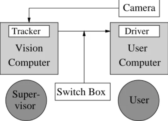
The Camera Mouse system currently involves two computers that are linked together – a “vision computer” and a “user computer.” A schematic plan of the system is shown in Fig. 1. The vision computer executes the visual tracking algorithm and sends the position of the tracked feature to the user computer. The user computer interprets the received signals and runs any application software the user wishes to use. The functionalities of the two computers could be integrated into one computer, but the current setup assures sufficient processing power for the visual tracking and allows a supervisor to monitor the tracking performance without interrupting the user’s actions.
User
TrackerVision
Computer
User
Computer
DriverCamera
Super-visor
Switch Box
Figure 1: The Camera Mouse System.
2.1
Vision Computer
The vision computer receives and displays a live video of the user sitting in front of the user computer. The video is taken by a camera that is mounted above or below the monitor of the user computer. Watching this video, the user or an attending care provider clicks with the vision computer’s mouse on the feature in the image to be tracked, perhaps the tip of the user’s nose. The camera’s remote control can be used to initially adjust the pan and tilt angles of the camera and its zoom so that the desired body feature is centered in the image. The vision system determines the coordinates of the selected feature in the initial image, and then computes them automatically in subsequent images. The coordinates of the tracked feature in each image frame are sent to the
Figure 2 shows a thirty-month old user of the Camera Mouse system and her tracked face on the monitor of the vision computer. Here the vision algorithm is tracking her lower lip. Figure 3 shows her in front of the user computer with the camera placed underneath the user computer’s monitor.
(a) (b)
Figure 2: (a) Thirty-month oldCamera-Mouseuser with cerebral palsy. (b) The visual tracking interface of the vision computer.
Figure 3: The Camera Mouse user playing with educational software. The video camera is placed underneath the user computer’s monitor.
2.2
User Computer
The user computer executes any commercial or custom software application the user chooses. It runs a special driver program in the background that takes the signals received from the vision computer, scales them to x, y
coordinates in the current screen resolution, and then substitutes them for the coordinates of the cursor. The driver program is based on software developed for the EagleEyes system [7] and runs independently from the user’s chosen application. The Camera Mouse acts as the mouse, and a manual switch box, shown in Fig. 1, is used to toggle to the standard mouse and back.
The driver program contains adjustments for horizontal and vertical “gain” factor. A high gain factor causes small movements of the head to move the mouse pointer greater distances, though with less accuracy. There is a similarity between adjusting the gain and adjusting the camera’s zoom. When the gain is adjusted, the coordinates of the feature being tracked are scaled by the specified amount. Changing the zoom of the camera, however, causes the vision algorithm to track the desired feature with either less or more detail. If the camera is zoomed-in on a feature, the feature will encompass a greater proportion of the sceen and thus small movements by the user will display larger movements of the cursor. Conversly, if the camera is zoomed-out, the feature will encompass a smaller proportion of the screen, and thus larger movements will be required to move the cursor.
Many programs require mouse clicks to select items on the screen. The driver program can be set to generate mouse clicks based on “dwell time.” When this option is selected, a mouse click is generated by the driver and received by the application program if the user keeps the mouse pointer within a 30-pixel radius for 0.5 seconds (s). These radius and timing parameters are typical choices, and can be adjusted according to application needs. The driver program also has an optional exponential smoothing filter. This can be used to smooth out tremors in the feature being tracked.
3
Tracking Algorithm
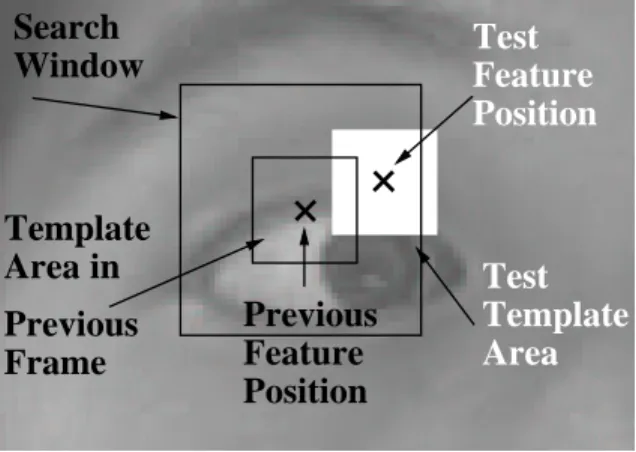
When the user initially clicks on the feature to be tracked, a square is drawn around the feature, and the subimage within this square is cropped out of the image frame. The cropped subimage is used as a “template” to determine the position of the feature in the next image frame. To find this position, the tracking algorithm uses the template to search for the feature in a “search window” that is centered at the position of the feature in the previous frame. The template is shifted through this search window and correlated with the underlying subimages. The window is defined to contain the centers of all subimages tested. Figure 4 illustrates template and search window positions.
Since a new frame is received within a thirtiest of a second, the template is usually very similar to the brightness pattern of the feature in the new frame, which can be found by searching for the best-correlated
subim-age. The assumption that corresponding brightness patterns in subsequent frames are constant, the “constant brightness assumption,” is often made when designing algorithms for motion analysis in images [15, 3].
Window
Search
Template
Test
Previous
Feature
Position
Area
Template
Test
Feature
Position
Previous
Frame
Area in
Figure 4: The search window is shown as a large square. It is centered around the estimated location of the feature in the previous frame. In the current frame, the template is shifted through the window. At each spatial lag, its correlation with the underlying subimage is computed. The location of a test subimage is shown in white. The best-correlated subimage is used as the new template in the subsequent frame. Its center is the new estimate of the feature’s position.
Each subimage s(x, y) in the search window is matched with the template subimage t(x, y) that is cropped from the previous frame. As a measure of match, the normalized correlation coefficient
r(s, t) =A Ps(x, y)t(x, y) −Ps(x, y)Pt(x, y) σsσt (1) is used, where σs = q APs(x, y)2 −(Ps(x, y))2 andσt= q APt(x, y)2
−(Pt(x, y))2 andA is the number
of pixels in templatet(x, y). The normalized correlation coefficient is invariant to uniform variations in shading i.e., r(s, t) = r(as+b, t) for some constants aand b. It can therefore handle some violations of the constant brightness assumption.
The subimage with the highest correlation coefficient among all subimages in the search window is determined. It serves two purposes. First, its center coordinates are transfered to the user computer to be interpreted as cursor coordinates. Second, it is cropped from the current frame and becomes the template that is used to search for the best matching subimage in the next frame. The process repeats and the template is updated for each image frame. This updating of the template ensures that a strong match can be produced in
each frame and that the motion of the initially selected feature is tracked. If at any time a low correlation is obtained and the template no longer resembles the desired feature, the supervising operator is free to re-click on the feature on the screen, thereby updating the template manually.
4
Choice of Parameters
The tracking performance of the Camera Mouse is a function of template and search window sizes and the velocity of the feature’s motion. It also depends on the choice of the feature as will be shown in Section 6, and the speed of the vision computer’s processor. A large search windowis useful for finding a feature that moves quickly. A large templatesize is beneficial, because it provides a large sample size for determining the sample means and variances in the computation of the normalized correlation coefficient. Small templates are more likely to match with arbitrary background areas because they often do not have enough brightness variations, e.g., texture or lines, to be recognized as distinct features. Reference [4] discusses this phenomenon in detail and explains that the size of the template is not the only issue, but more importantly, tracking performance depends on the “complexity” of the template.
Large template or search window sizes require computational resources that may reduce the frame rate substantially. If many incoming frames are skipped, which means that the rate of the frames that are used for tracking drops well below 30 Hz, the constant brightness assumption may not hold for the tracked feature, even if it is still located within the search window. For the worse, when frames are skipped, it is likely that the feature moves outside the search window, far away from its previous position.
To quantify tracking performance, a match between a template and the best-matching subimage within the search window is called sufficientif the normalized correlation coefficient is at least 0.8. Correlation coefficients below 0.8 describeinsufficient matches. Insufficient matches occur when the feature cannot be found in the search window because the user moved quickly or moved out of the camera’s field of view. This results in an undesired match with a feature that is different from the initially selected feature. For example, if the right eye is being tracked and the user turns his or her head quickly to the right, so that only the profile is seen,
the right eye becomes occluded. A nearby feature, for example, the top of the nose, may then be cropped and tracked instead of the eye.
The threshold of 0.8 was chosen after extensive experiments that resulted in an average correlation of 0.986 over 800 frames for a match between template and best-correlated subimage, while the correlation for poor matches varied between 0.7 and 0.8. If the correlation coefficient is above 0.8, but considerably less than 1, the initially selected feature may not be in the center of the template anymore and attention has “drifted” to another nearby feature. In this case, tracking performance, however, is usually sufficient for the applications tested.
Figure 5 illustrates how an increase in the width of the search window affects the frame rate and the correlation between template and best-matching subimages. In these experiments, the tip of the computer user’s nose was being tracked while the user tried to move the screen pointer at a consistent speed. On average, the tracked feature changed its position by 7 pixels in 1/30 s. Nine parameter values for the search window width were tested. For each value, 800 image frames were captured and processed. The averages and standard deviations reported in Fig. 5 are computed over these 800 frames. As can be seen in the bottom graph, the number of insufficient matches among 800 processed frames is zero for window widths below 44 pixels. If the window width is set to 44 or more pixels, the frame rate drops to about 20 Hz (see top graph). The correlation coefficient of the best match then drops, the standard deviation of the best match increases (see middle graph), and several insufficient matches are found (see bottom graph).
In order to find good parameter values for window and template sizes that balance the tradeoff between number of frames examined per second and the sizes of the areas searched and matched, the time it takes to search for the best correlation coefficient is measured as a function of window and template widths (see Fig. 6). A template size of 15×15 pixels is large enough to capture a meaningful body feature and small enough so that
0 10 20 30 40 34 36 38 40 42 44 46 48 50
Width of Search Window (pixels)
Average Frame Rate (frames/s)
1 .95
34 36 38 40 42 44 46 48 50
Width of Search Window (pixels)
Average Best Correlation Coefficient
0 2 4 6 8 10 34 36 38 40 42 44 46 48 50
Width of Search Window (pixels)
Number of Mismatches
Figure 5: Tracking experiments to determine the search window size. The tip of the computer user’s nose was being tracked while the user moved the screen pointer 7 pixels in 33 ms on average. Nine parameter values for the search window width were tested. For each value, 800 image frames were captured and processed. The averages and standard deviations are taken over the 800 processed frames. An increase in the width of the search window affects the average frame rate (top) and mean and standard deviations of the correlation between template and best-matching subimage (middle). While the frame rate is close to 30 Hz, the best matching templates correlate highly and the tracking algorithm is able to reliably capture the motion of the feature. However, once the search size becomes large enough to affect the frame rate, the tracking performance suffers and insufficient matches are made (bottom).
10 20 30 40 50 60 70 5 10 15 20 25 30 ms Width of Template (pixels)
Processing Time for Correlation with 40x40 Search Window
10 20 30 40 50 60 70 20 30 40 50 60 ms
Width of Search Window (pixels)
Processing Time for Correlation with 15x15 Template
Figure 6: The graph on the left shows the processing time of the normalized correlation coefficient as a function of the width of the template, given a search window width of 40 pixels. The graph on the right shows the processing time of the normalized correlation coefficient as a function of the width of the search window, given a fixed 15×15 size template. A frame rate of 30 Hz = 33 ms can be ensured if the respective sizes of the cropped
template and the search window are 15×15 and 40×40 pixels.
5
Hardware Specifications
5.1
Vision Computer
The vision computer is a 550 MHz Pentium II PC with the Windows NT operating system, a Matrox Meteor-II video capture board and a National Instruments Data Acquisition Board. The video capture board digitizes the analogue NTSC signal received from the video camera, a Sony EVI-D30 CCD camera with zoom, tilt and pan mechanisms. The video capture board supplies 30 color images of size 640×360 per second. To guarantee
real-time performance, the vision algorithm processes only 320×240 pixels, i.e. half of the available resolution,
at an average frame rate of 30 Hz. It uses a template size of 15×15 pixels and a search window of 40×40 pixels.
The vision algorithm computes the x, y coordinates of the tracked feature, and passes them to the National Instruments Data Acquisition Board. This board transforms the coordinates into voltages that are then sent to the user computer.
5.2
User Computer
The user computer is a 550 MHz Pentium II PC with the Windows 98 operating system and a National In-struments Data Acquisition Board. A special driver program uses the National InIn-struments card to obtain the voltages and then converts them into screen coordinates for the mouse pointer. The driver program runs in the background and acts as a regular mouse for any customized or commercial application software.
6
Discussion of Feature Choices
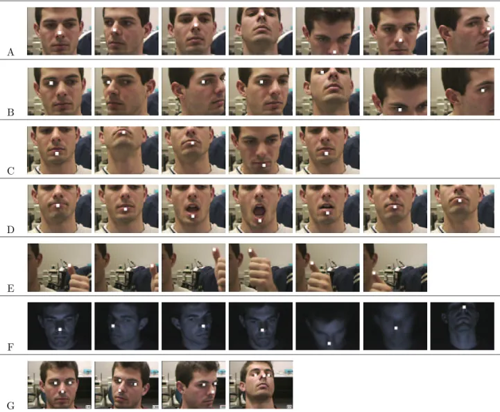
A variety of features were tested in an attempt to find body points that can be easily moved by the user and reliably tracked by the system. Since the appearance of body features differs among people, tracking performance varies between individuals. Several features, however, were reliably tracked across the test group. Figure 7 illustrates the tracking performance of several features, while Fig. 8 illustrates the brightness variations of the template images.
6.1
Nose Tracking
The nose is a desirable tracking feature for several reasons. First, it is easy for a computer user to point his or her nose in a particular direction while watching the screen. The nose is essentially in the center of the face and does not become occluded when the user’s head moves significantly. Second, the nose template tends to contain a good amount of brightness contrast to its surrounding features.
The majority of testing with the Camera Mouse was done under normal overhead lighting. In such an environment, the nose tends to be brighter than the rest of the face as it is slanted and therefore oriented towards the overhead light.
In image sequence A in Fig. 7, the tip of the nose was tested as a feature. It was tracked throughout the 1000 recorded frames and not lost once. This excellent tracking performance can be reproduced for arbitrarily long time periods as long as the user understands the constraints of the system and cooperates accordingly. If he or she moves so quickly that the nose tip leaves the search window, the system cannot track it. Given the
A B C D E F G
Figure 7: The eye, nose, mouth, and thumb were tracked to determine features that can be tracked reliably (A– E). Sequence F shows that the nose can be tracked even if the laboratory is dark, and only the screen illuminates the user’s face. Sequence G shows tracking of a set of features. Each test sequence contains 1000 images. A representative subset of each sequence is shown. The tracked subimages surrounding the features have been filled white for better viewing. They are 15 pixels wide in sequences A–F, and 10 pixels wide in sequence G.
nose eye lower lip and chin thumb nose (dark setting)
Figure 8: Examples of the templates that are used to identify the feature being tracked. Each template is 15×15
pixels in size. Here they have been enlarged in order to view the brightness levels that make up each template. They are templates of the nose, the eye, the lower lip and crevice under the lip, the thumb, and the nose in a room without any light except for that reflected by the monitor.
selection of parameters in Section 4, this can only occur with a very drastic motion, for example, a violent shaking of the head or an extremely jerky movement. The system also loses the nose feature if the user covers the nose or moves out of the camera’s field of view. The drifting phenomenon, as discussed in Section 4, may occur for some users. For example, the template may slowly drift up the bridge of the nose. For such users, the bottom part of the nose, i.e., the area between the nostrils, is a more useful feature. It works better, because the neighboring nostrils provide good contrast points, and the shadow that is generally present under the nose distinguishes the bottom part of the nose from the cheeks or lips.
6.2
Eye Tracking
There has been some success in tracking the eye, but not to the extent of determining gaze direction. Image sequence B in Fig. 7 shows the eye being tracked at various positions. Note that it is not the pupil, but the whole eye that is being tracked in sequence B. The brightness contrast between white eye sclera and dark iris and pupil, along with the texture of the eyelid provides a distinctive template. Although the eye can be tracked well, it has not been used effectively with a Camera Mouse application, because it is a relatively difficult feature to move while viewing the screen. Also, rotating the head may cause the eye to be blocked by the nose and not be visible at all.
6.3
Lip Tracking
As shown in image sequences C and D in Fig. 7, tracking the area of the lower lip and cleft has also been tested extensively. This feature can be tracked successfully on many individuals. It is a good tracking location because
of the brightness difference between the lip and the cleft. People with large lips tend to have a shadow cast upon the cleft that enhances the brightness difference between the upper and lower image portions of the template and makes vertically drifting templates very unlikely. Furthermore, the outline of the lip forms a curved line that helps control lateral drifting and keeps the template centered on the lips.
When testing this feature in an attempt to track head movement, we noticed that it also works very well in tracking mouth movement alone. This is an important result because it stresses the flexibility of the system. The range of muscle control varies widely between people with severe disabilities, and head movement is not always an option. Opening and closing the mouth is a possibility for many people though and can allow cursor motion in either a vertical or horizontal direction. For example, the Rick Hoyt Spelling Program [13] requires only horizontal cursor movements that can be produced by converting the tracked up-down movements of the lips into horizontally changing cursor coordinates.
6.4
Thumb Tracking
To test other body features, not just facial features, the thumb was selected. Although it was tracked successfully, as shown in sequence E in Fig. 7, it has two main flaws as a tracking point. First, the camera has difficulties in focusing on it. As can be seen in sequence E, the thumb takes up such a small portion of the screen that the camera’s auto-focus mechanism focuses on the objects in the background and not the thumb. This distorts the outline of the thumb and makes it difficult to track. Thus, if the thumb is used as a tracking point, it should be held close to the body or some other object in the background, so that the camera is able to focus on the thumb correctly. Another problem in using the thumb is its small surface area, which can move out of the search window easily. If this occurs, the tracking program will lose the thumb entirely and begin tracking a new point in the background. This means if the thumb is used, slow movements are necessary.
6.5
Dark Lighting
A set of test images was taken in a room with no natural or artificial light except for what was produced by the computer monitor. As can be seen in sequence F in Fig. 7, the Camera Mouse was able to track the person’s
nose in these lighting conditions.
6.6
Multiple Points
Although the current system does not track multiple points, some initial experimentation was done to test such tracking. In the future, multiple-point tracking may be utilized, for example, to compute the distances between the nose and pupils for gaze detection. This would result in a more specialized tracking system. The current version’s strength is its generality – any feature can be selected for tracking.
7
Experimental Results
7.1
People Without Disabilities
The effectiveness of the Camera Mouse was tested with a group of 20 computer users in two main experiments. Each user was given a brief introduction to how the system worked and then allowed to practice moving the cursor for one minute. After the practice period, each user was asked to play a video game. The one-minute practice period was perceived as sufficient training time by the users, who prefered to “train on the job” while playing a computer game.
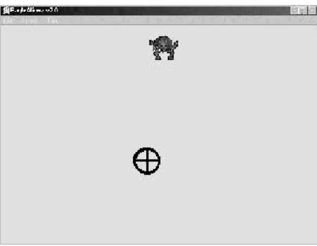
In the computer game, “aliens” appear at random locations on the screen one at a time as shown in Fig. 9. In order to “catch an alien,” users must point the cursor at the alien. No mouse clicks are generated. Each user was asked to “catch ten aliens” three times with the mouse and three times with the Camera Mouse. The type of mouse that was tested first was chosen randomly. For each test, the user’s time to play the game was recorded. Table 1 reports the times to “catch one alien” with the regular mouse and the Camera Mouse as averages for the 20 users. The average time to play the video game with the regular mouse was faster than the Camera Mouse by a factor of about 1.6. The difference is statistically highly significant (P < 0.001) [1]. Practicing the video game seems to improve input speed, since on average the game was played faster in each consecutive test – both with the standard mouse and the Camera Mouse.
Figure 9: Aliens Game: The user controls the position of the circled cross with either the standard mouse or the
Camera Mouse. An alien has appeared at random on top of the screen. In order to “catch the alien,” the user must move the circled cross up until it touches the alien.
TABLE 1
Timing Comparison Between Regular Mouse and Camera Mouse Usage
Sample mean and standard deviationσof the lengths of three testswith the “Aliens Game” performed by 20 healthy subjects. Aliens Game
Regular Mouse Camera Mouse
Mean σ Mean σ
Test 1 0.50 s 0.07 s 0.75 s 0.12 s Test 2 0.43 s 0.07 s 0.75 s 0.18 s Test 3 0.40 s 0.07 s 0.66 s 0.10 s
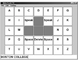
program’s interface, shown in Fig. 10, contains 26 cells to type the letters of the alphabet, two cells to type the space symbol, a cell to delete misspelt letters, and two cells to activate the speech synthesizer, which then speaks the just typed words. To activate a cell, a mouse click is required. If the Camera Mouse is used, a mouse click is simulated after the pointer has occupied the cell for more than 0.5 s. In our experiments, we fixed this “dwell time” for comparison purposes. In general, the dwell time can be adjusted for a particular user. The process of clicking a regular mouse button takes 0.05 s on average. The interface also contains four cells without functionality, which can be used to rest the cursor. These cells are important to avoid the “Midas Touch Problem” [18] that everything the mouse pointer touches is selected.
In the spelling-board experiment, each user was asked to test the program with the standard mouse and the Camera Mouse three times to spell out and speak “Boston College.” The decision which type of mouse
Figure 10: Spelling Board: The user controls what is typed at the bottom of the interface by selecting the letters with the standard mouse or theCamera Mouse. “Boston College” was typed here.
to test first was made randomly. Each user was able to spell the message with the Camera Mouse, which shows that it provides a viable method of controlling the cursor. The timing results of the experiments are summarized in Table 2. The regular mouse provides a faster interface with the spelling board than the Camera Mouse. The difference is statistically highly significant (P <0.001).
Spelling with the regular mouse was on average more than twice as fast as the Camera Mouse. In particular, in the third test, the factor is 2.1 = 25.24s/11.90s. The dwell time required for the Camera Mouse is an important element in this comparison. When the difference in dwell time for the Camera Mouse and click time for the regular mouse is accounted for by excluding these times from the overall lengths of the communication tests, the regular mouse was still faster than the Camera Mouse, but only by a factor of 1.6 = 18.24s/11.20s. This is the same factor obtained for the “alien game” that did not require any mouse clicks to be generated.
A short dwell time will increase the rate of communication. However, if the dwell time is too short, chances increase that cells are unintentionally selected. Further studies are needed to determine the dwell time that provides the best rate of communication for a particular user. We expect this to be dependent on the user’s abilities to control his or her body movements.
TABLE 2
Timing Comparison Between Standard Mouse and Camera Mouse Usage
Sample mean and standard deviationσof the lengths of three communication testswith the spelling-board interface performed by 20 healthy subjects. Spelling Board Experiments
Regular Mouse Camera Mouse
Mean Time Mean Time
Including Excluding Including Excluding
Mouse Clicks σ Mouse Clicks σ
Test 1 15.29 s 14.59 s 2.88 s 28.67 s 21.67 s 3.58 s Test 2 12.48 s 11.78 s 2.23 s 26.67 s 19.67 s 3.32 s Test 3 11.90 s 11.20 s 1.55 s 25.24 s 18.24 s 2.70 s
7.2
People With Disabilities
A dozen people who cannot speak and have very limited voluntary muscle control have tried using the Camera Mouse to access the computer. Ten have cerebral palsy. Two have traumatic brain injury, one from an automobile accident, one from a motorcycle accident. Nine of the people are continuing to use the Camera Mouse. Six can use the Camera Mouse to spell using an onscreen keyboard system. Three of the people did not have sufficient muscle control to use the Camera Mouse. They are using EagleEyes to control the mouse pointer by moving their eyes. One of the people who was not successful was close and will be given additional opportunities to try the Camera Mouse in the future. The results are summarized in Table 3.
TABLE 3
Summary of results for the first dozen people with disabilities to try the Camera Mouse.
Age Gender Condition Results Continuing
to Use ? 2 M Cerebral Palsy Obtaining a system for home. Yes 3 F Cerebral Palsy First regular user with home system. Yes 6 F Cerebral Palsy Spelled name. Obtaining a home system. Yes 8 M Cerebral Palsy Spells naughty words and laughs. Yes
11 M Cerebral Palsy Obtaining a home system. Yes
14 M Cerebral Palsy Spells words. Obtaining a home system. Yes 15 M Cerebral Palsy Close, but could not control reliably. No 19 M Cerebral Palsy Does not have sufficient muscle control. No 23 M Traumatic Brain Injury Does not have sufficient muscle control. No 31 M Traumatic Brain Injury Spelled ”TAKE OFF DAD” Yes
37 M Cerebral Palsy Spelled ”MERRY CHRISTMAS” Yes
Most users tested the Camera Mouse system at the “Campus School” at Boston College. The Campus School provides a combination of educational and therapeutic services to children ages 3 to 21 who have multiple disabilities including cerebral palsy and traumatic brain injury. Various systems such as switch-based and EOG-based systems [7] provide these children computer access that is reliable but not without barriers. The Camera Mouse has proven to be a useful alternative. It does not require direct physical contact, allows direct selection of choices, and is easier to operate for both supervisor and user. The children were able to master the Camera Mouse system within two hours of use. For those who have muscular control of a body feature like the head, foot, or hand, the Camera Mouse has been very effective.
There is an important story to be told about each of the dozen individuals listed in Table 3. One user is a eight-year old child with cerebral palsy. He had been using EagleEyes for one year but has had problems with the system due to his perspiration and dislike of the physical contact with the electrodes. Once he tried the Camera Mouse, it was immediately clear that he understood that he was controlling the cursor. It took two hours, spread over a week, to determine the best tracking point for this user. The feature of choice for him is his foot. Using his foot, he is able to consistently “catch ten out of ten aliens” using the game described in Section 7. His foot can be tracked without requiring frequent supervisor intervention.
A three-year old girl with cerebral palsy has used the system at home regularly. Her mother reports: “When she was 16 months old we had the opportunity to try a computer that was accessed [using EagleEyes]. At this time we had no idea if or how much [she] understood. To our amazement she followed every direction that was given her. Can you just imagine the joy we had watching our daughter exploring her environment [..] ? The possibilities seem endless now. Since then [she] has become more sophisticated with this computer. [..] [The Camera Mouse] has given her a way to communicate her thoughts, it gives the school that she is attending a way to adapt the curriculum so that [she] can participate in a REGULAR preschool, it puts [her] in a situation where people can see her ABILITIES rather than her disabilities [..]. When [she] uses the Camera Mouse, she is alert, attentive, and responsive. She controls the mouse with her chin and plays with educational software.”
pre-school regular education program. Despite her inability to vocalize and her very limited muscle control, she is functioning at grade level and above in most areas of cognitive and social development. Our goal now is to help her access the regular schoolwork that is afforded her peers.
Another user is nineteen years old and has a traumatic brain injury. This user learned how to use the camera mouse quickly and had fluid control of the cursor after ten minutes of use. He does have less control of horizontal movements though, due to a lack of complete muscular control.
The Camera Mouse system has also been used by a twenty-three year old man with traumatic brain injury, who has some control of his thumb. By placing his hand on the white tray of his wheelchair and focusing the camera on his thumb, he can move the mouse pointer with small movements of his thumb.
The gentleman who is 58 with cerebral palsy spends his time in bed at home in New Jersey. He had no expressive language ability and no voluntary movement below the neck. We were approached by his 80+ year old father who wanted his son to be able to communicate before he died. We set up a prototype system in the home. The gentleman is now using the Camera Mouse to communicate with his father and access a variety of software.
8
Conclusions
The experiences with the Camera Mouse system are very encouraging. They show that the Camera Mouse can successfully provide computer access for people with severe disabilities. It is a user-friendly communication device that is especially suitable for children. The system tracks many body features and does not have any user-borne accessories, so it is easily adaptable to serve the special needs of people with various disabilities. To meet the current demand, additional Camera Mouse systems are being installed. A single-computer version of the system is being developed. Future work will incorporate a detection component into the visual tracking algorithm.
Acknowledgements
The authors thank Philip A. DiMattia, Director of the Campus School at Boston College, for his support.
References
[1] D. G. Altman. Practical Statistics for Medical Research. Chapman and Hall/CRC, Baco Raton, FL, 1991. [2] Assistive technology products, (2001, Jun.), Madentec, Edmonton, Canada. [Online]. Available:
http://www.madentec.com.
[3] M. Betke, E. Haritaoglu, and L. S. Davis. Real-time multiple vehicle detection and tracking from a moving vehicle. Mach. Vis. Appl., 12(2):69–83, Sep. 2000.
[4] M. Betke and N. C. Makris. Recognition, resolution and complexity of objects subject to affine transforma-tion. Int. J. Comput. Vis., 44(1), Sep. 2001.
[5] C. Brown. Assistive technology computers and persons with disabilities.Commun. ACM, 35(5):36–45, 1992. [6] Y. L. Chen, F. T. Tang, W. H. Chang, M. K. Wong, Y. Y. Shih, and T. S. Kuo. The new design of an infrared-controlled human-computer interface for the disabled. IEEE Trans. Rehab. Eng., 7(4):474–481, Dec. 1999.
[7] P. A. DiMattia, F. X. Curran, and J. Gips. An Eye Control Teaching Device for Students without Language Expressive Capacity – EagleEyes. The Edwin Mellen Press, Lampeter, UK, 2001. See also http://www.bc.edu/eagleeyes.
[8] D. G. Evans, R. Drew, and P. Blenkhorn. Controlling mouse pointer position using an infrared head-operated joystick. IEEE Trans. Rehab. Eng., 8(1):107–117, 2000.
[9] Eye tracking system (2001, Jun.), Applied Science Laboratories, Bedford, MA. [Online]. Available: http://www.a-s-l.com.
[10] Eyegaze system (2001, Jun.), LC Technologies, Fairfax, VI. [Online]. Available: http://www.lctinc.com. [11] J. Gips, M. Betke, and P. A. DiMattia. Early experiences using visual tracking for computer access by
people with profound physical disabilities. In Proc. 1st Int. Conf. Universal Access in Human-Computer Interaction, New Orleans, LA, August 2001.
[12] J. Gips, M. Betke, and P. Fleming. The Camera Mouse: Preliminary investigation of automated visual tracking for computer access. InProc. RESNA 2000 Annu. Conf., pages 98–100, Orlando, FL, Jun. 2000. [13] J. Gips and J. Gips. A computer program based on Rick Hoyt’s spelling method for people with profound
special needs. InProc. Int. Conf. Computers Helping People with Special Needs, pages 245–250, Karlsruhe, Germany, July 2000.
[14] J. Gips, P. Olivieri, and J. J. Tecce. Direct control of the computer through electrodes placed around the eyes. In M. J. Smith and G. Salvendy, editors, Human-Computer Interaction: Applications and Case Studies, pages 630–635. Elsevier, 1993.
[15] B. K. P. Horn. Robot Vision. The MIT Press, Cambridge, MA, 1986. pp. 280–283.
[16] T. Hutchinson, K. P. White JR., W. N. Martin, K. C. Reichert, and L. A. Frey. Human-computer interaction using eye-gaze input. IEEE Trans. Syst. Sci. Cybern., 19(6):1527–1533, 1989.
[17] Infrared head-mounted mouse alternative, (2001, Jun.), Don Johnston, Inc., Penny & Giles HeadWay. [Online]. Available: http://www.donjohnston.com.
[18] R.J.K. Jacob. What you look at is what you get. Computer, pages 65–66, July 1993.
[19] Z. A. Keirn and J. I. Aunon. Man-machine communications through brain-wave processing. IEEE Eng. Med. Biol., pages 55–57, May 1990.
[20] J. R. LaCourse and F. C. Hludik Jr. An eye movement communication-control system for the disabled.
IEEE Trans. Biomed. Eng., 37(12):1215–1220, 1990.
[21] C.H. Morimoto, D. Koons, A. Amit, M. Flickner, and S. Zhai. Keeping an eye for HCI. In Proc. XII Brazilian Symposium on Computer Graphics and Image Processing, pages 171–176, 1999.
[22] W. J. Perkins and B. F. Stenning. Control units for operation of computers by severely physically handi-capped persons. J. Med. Eng. Technol., 10(1):21–23, 1986.
[23] Permobil EyeTrace System (2001, Jun.), Permobil Meditech AB, Timra, Sweden. [Online]. Available: http: //www.algonet.se/ ˜eyetrace.
[24] M. Pregenzer and G. Pfurtscheller. Frequency component selection for an EEG-based brain to computer interface. IEEE Trans. Rehab. Eng., 7(4):413–419, 1999.
[25] R. B. Reilly and M. J. O’Malley. Adaptive noncontact gesture-based system for augmentative communica-tion. IEEE Trans. Rehab. Eng., 7(2):174–182, 1999.
[26] G. A. Rinard, R. W. Matteson, R. W. Quine, and R. S. Tegtmeyer. An infrared system for determining ocular position. ISA Trans., 19(4):3–6, 1980.
[27] R. C. Simpson and H. Horstmann Koester. Adaptive one-switch row-column scanning. IEEE Trans. Rehab. Eng., 7(4):464–473, 1999.
[28] G. Vanderheiden. Human interface design and the handicapped user. InProc. Computer-Human Interaction Conf., pages 296–297, 1986.
[29] L. Young and D. Sheena. Survey of eye movement recording methods. Behavior Research Methods & Instrumentation, 7(5):397–429, 1975.
Margrit Betke’s research area is computer vision. She is particularly interested in real-time applications to rehabilitation engineering and biomedical imaging. Prof. Betke received her Ph. D. and S. M. degrees in Computer Science and Electrical Engineering from the Massachusetts Institute of Technology in 1995 and 1992, respectively. After completing her Ph. D. thesis on “Learning and Vision Algorithms for Robot Navigation,” at MIT, she spent two years as a Research Associate in the Institute for Advanced Computer Studies at the University of Maryland. She was also affiliated with the Computer Vision Laboratory of the Center for Automation Research at UMD. She was an Assistant Professor at Boston College for three years and is a Research Scientist at the
Massachusetts General Hospital and Harvard Medical School. In July 2000, she joined Boston University as an Assistant Professor in Computer Science.
James Gips’research interests generally are in human-computer interaction, especially in developing technology to allow people with profound disabilites to interact with the computer. Prof. Gips received his S. B. from the Massachusetts Institute of Technology in 1967, and his M. S. and Ph. D. in Computer Science from Stanford in 1968 and 1974, respectively. He is currently a Professor in the Computer Science Department at Boston College. For the EagleEyes Project, Prof. Gips was a Finalist, Discover Magazine Technological Innovation Awards, in the area of Computer Hardware and Electronics, 1994.
Peter Fleming graduated with a B. A. in Computer Science from Boston College in 2000. He currently is working for Accenture.