European Telecommunications Standards Institute
European Standard (Telecommunications series)
Television systems;
625-line television
Wide Screen Signalling (WSS)
EBU UER
Reference
REN/JTC-WSS-2 (2q000j1c.PDF)
Keywords
Wide screen, signalling, analogue, TV
ETSI Secretariat
Postal address
F-06921 Sophia Antipolis Cedex - FRANCE
Office address
650 Route des Lucioles - Sophia Antipolis Valbonne - FRANCE
Tel.: +33 4 92 94 42 00 Fax: +33 4 93 65 47 16
Siret N° 348 623 562 00017 - NAF 742 C Association à but non lucratif enregistrée à la
Sous-Préfecture de Grasse (06) N° 7803/88
Internet
[email protected] http://www.etsi.fr http://www.etsi.org
Copyright Notification
No part may be reproduced except as authorized by written permission. The copyright and the foregoing restriction extend to reproduction in all media.
© European Telecommunications Standards Institute 1998. © European Broadcasting Union 1998.
Contents
Intellectual Property Rights...4
Foreword ...4
Introduction ...4
1
Scope ...5
2
Reference ...5
3
Definition, symbols and abbreviations...5
3.1 Definition ... 5
3.2 Symbols and abbreviations ... 5
4
Requirements ...6
4.1 Line code ... 6
4.1.1 Position ... 6
4.1.2 Clock frequency ... 7
4.1.3 Pulse shape ... 7
4.1.4 Signal amplitude... 7
4.1.5 Modulation coding ... 7
4.1.6 Preamble... 8
4.1.7 Data bits ... 8
4.1.8 Odd parity bit ... 8
4.2 Information content of data bits ... 10
4.2.1 Data group 1... 10
4.2.1.1 Aspect ratio... 10
4.2.2 Data group 2, enhanced services ... 11
4.2.2.1 Film bit ... 11
4.2.2.2 Colour coding bit ... 11
4.2.2.3 Helper bit... 11
4.2.2.4 Bit b7 ... 11
4.2.3 Data group 3, subtitles... 12
4.2.3.1 Subtitles within Teletext bit ... 12
4.2.3.2 Subtitling mode... 12
4.2.4 Data group 4, others ... 12
4.2.4.1 Surround sound bit... 12
4.2.4.2 Copyright information ... 13
Annex A (informative):
Rules of operation...14
A.1
Receiver display formats...14
A.2
Subtitling...14
A.3
Procedure in absence of signalling ...15
Annex B (informative):
Recommendations...16
B.1
Low pass pre-filtering ...16
B.2
Response time on a change in the received signalling information...16
Annex C (informative):
Guidelines ...17
C.1
Copyright information...17
Intellectual Property Rights
IPRs essential or potentially essential to the present document may have been declared to ETSI. The information pertaining to these essential IPRs, if any, is publicly available for ETSI members and non-members, and can be found in ETR 314: "Intellectual Property Rights (IPRs); Essential, or potentially Essential, IPRs notified to ETSI in respect of ETSI standards", which is available free of charge from the ETSI Secretariat. Latest updates are available on the ETSI Web server (http://www.etsi.fr/ipr or http://www.etsi.org/ipr).
Pursuant to the ETSI Interim IPR Policy, no investigation, including IPR searches, has been carried out by ETSI. No guarantee can be given as to the existence of other IPRs not referenced in ETR 314 (or the updates on the ETSI Web server) which are, or may be, or may become, essential to the present document.
Foreword
This European Standard (Telecommunications series) has been produced by the Joint Technical Committee (JTC) of the European Broadcasting Union (EBU), Comité Européen de Normalisation ELECtrotechnique (CENELEC) and the European Telecommunications Standards Institute (ETSI).
NOTE: The EBU/ETSI JTC was established in 1990 to co-ordinate the drafting of standards in the specific field of broadcasting and related fields. Since 1995 the JTC became a tripartite body by including in the Memorandum of Understanding also CENELEC, which is responsible for the standardization of radio and television receivers. The EBU is a professional association of broadcasting organizations whose work includes the co-ordination of its members' activities in the technical, legal, programme-making and programme-exchange domains. The EBU has active members in about 60 countries in the European broadcasting area; its headquarters is in Geneva.
European Broadcasting Union
CH-1218 GRAND SACONNEX (Geneva) Switzerland
Tel: +41 22 717 21 11 Fax: +41 22 717 24 81
National transposition dates
Date of adoption of this EN: 5 Septembre 1997 Date of latest announcement of this EN (doa): 31 December 1997 Date of latest publication of new National Standard
or endorsement of this EN (dop/e): 30 June 1998 Date of withdrawal of any conflicting National Standard (dow): 30 June 1998
Introduction
For a smooth introduction of new television services with a 16:9 display aspect ratio in PAL and SECAM standards, it is necessary to signal the aspect ratio used together with some switching information to the television receiver. The receiver should be capable of reacting automatically to this information by displaying the video information in a specified aspect ratio. This signalling is to be considered separately from the type of system used, but it should allow transmission of system related switching information as well.
The present document permits the later allocation of additional switching information, related to the introduction of enhanced television services.
The present document is applicable for 625-line PAL and SECAM television systems, but there is potential to adopt it to other standards as well.
1
Scope
This European Standard (Telecommunications series) is applicable to 625-line PAL and SECAM systems in use, in case, where wide screen signalling is required by the broadcasters.
It specifies the wide screen signalling information, the coding and the way of incorporating the coded information into a 625-line system.
The wide screen signalling information contains information on the aspect ratio range of the transmitted signal and its position, on the position of the subtitles and on the camera/film mode. Furthermore signalling for EDTV and for surround sound is included. Some bits are reserved for future use.
The present document specifies the transmitted signal. Annex A gives the rules of operation for the minimum requirements for receiver display formats as well as for subtitling. Annex B gives recommendations. Annex C gives a guideline for copyright information.
2
Reference
References may be made to:
a) specific versions of publications (identified by date of publication, edition number, version number, etc.), in which case, subsequent revisions to the referenced document do not apply; or
b) all versions up to and including the identified version (identified by "up to and including" before the version identity); or
c) all versions subsequent to and including the identified version (identified by "onwards" following the version identity); or
d) publications without mention of a specific version, in which case the latest version applies.
A non-specific reference to an ETS shall also be taken to refer to later versions published as an EN with the same number.
[1] EBU Recommendation R62 (1990): "Recommendation dominant field for 625-line 50 Hz processing".
3
Definition, symbols and abbreviations
3.1
Definition
For the purposes of the present document, the following definition applies:
letterbox operation: Is the use of a picture format with an aspect ratio greater than 1,33, in such a way that empty
(black) lines are added to conform to a 4:3 transmission format.
3.2
Symbols and abbreviations
For the purposes of the present document, the following symbols and abbreviations apply: 0h falling sync edge
a aspect ratio
EDTV Enhanced Definition TeleVision Fs clock frequency
LSB Least Significant Bit MSB Most Significant Bit NRZ Non-Return-to-Zero
PAL Phase Alternation Line (Colour TV-System)
SECAM SequentiellE Couleur Avec Memoire (French Colour-TV System) Td data bit period
Ts sampling period WSS Wide Screen Signalling
4
Requirements
4.1
Line code
The following subclauses specify the line code of the Wide Screen Signalling (WSS).
4.1.1
Position
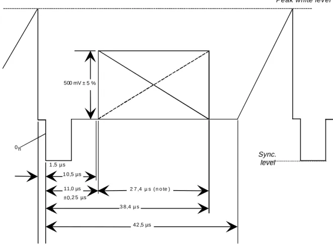
The signalling bits shall be transmitted as a data burst in the first part of line 23.
The position of the beginning of the Wide Screen Signalling bits shall be 11,0 ± 0,25 µs from 0h of the horizontal sync, as indicated in figure 1. This figure is intended to illustrate the position of the signalling bits in line 23. For the purpose of commonality between PAL and SECAM, the colour burst and chrominance sub-carrier are not shown.
500 mV ± 5 %
0 h
1 ,5 µ s 1 0,5 µs
11,0 µs 2 7 ,4 µ s ( n o te )
3 8,4 µ s
42 ,5 µs ±0,2 5 µs
Peak white level
Sync. level
NOTE: For optimum decoder performance, it is recommended that this period is free from other signals.
Figure 1: Position of status bit signalling in line 23
4.1.2
Clock frequency
The clock frequency shall be: Fs = 5 MHz (± 1 × 10⁻⁴); The period shall be: Ts = 200 ns.
4.1.3
Pulse shape
The pulse shaping function h(τ) shall be approximately a sine square: h
T T
elsewhere
s
( )τ ≈ sin πτ π τ
+
≤
2
2 2 0
2
2 | | T
S
The half amplitude pulse duration shall be: 200 ns ± 10 ns.
4.1.4
Signal amplitude
The signal amplitude with respect to a maximum video signal amplitude of 700 mV shall be: 0,5 V ± 5 %.
4.1.5
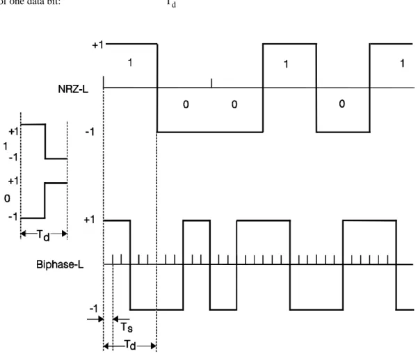
Modulation coding
Bi-phase coding shall be used in accordance with figure 2. Duration of one data bit: Td
The data bits shall be inserted in bi-phase-L, in which one data bit period equals 2 × 3 clock periods, whereby: Td = 6Ts
4.1.6
Preamble
The preamble contains a run-in and a start code. The preamble shall be in accordance with table 1.
4.1.7
Data bits
There shall be 14 bits in total. 1 out of these 14 bits shall be allocated to the error detection code. There shall be 13 data-bits available for transmission of information. The data bits shall be grouped in 4 data groups, see table 1.
4.1.8
Odd parity bit
For error detection, an odd parity bit has been introduced. The odd parity bit shall belong to the first 3 data bits only, see table 1.
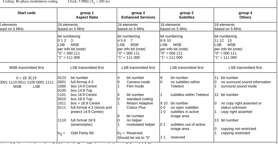
Table 1: Status bits transmission scheme Status bits transmission
Insertion: First half of line 23 Coding: Bi-phase modulation coding Clock: 5 MHz (Ts = 200 ns)
run-in Start code group 1
Aspect Ratio group 2 Enhanced Services group 3 Subtitles group 4 Others 29 elements
based on 5 MHz
24 elements based on 5 MHz
24 elements based on 5 MHz
24 elements based on 5 MHz
18 elements based on 5 MHz
18 elements based on 5 MHz bit numbering
0 1 2 3
LSB MSB
per info bit (note) "0" = 000 111 "1" = 111 000
bit numbering 4 5 6 7
LSB MSB
per info bit (note) "0" = 000 111 "1" = 111 000
bit numbering 8 9 10 LSB MSB per info bit (note) "0" = 000 111 "1" = 111 000
bit numbering 11 12 13 LSB MSB per info bit (note) "0" = 000 111 "1" = 111 000
MSB transmitted first MSB transmitted first LSB transmitted first LSB transmitted first LSB transmitted first LSB transmitted first 0 × 1F1C 71C7
1 1111 0001 1100 0111 0001 1100 0111
MSB LSB
0 × 1E 3C1F
0001 1110 0011 1100 0001 1111
MSB LSB
0123 bit number 0001 full format 4:3 1000 box 14:9 Centre 0100 box 14:9 Top 1101 box 16:9 Centre 0010 box 16:9 Top 1011 box > 16:9 Centre 0111 full format 4:3 (shoot and
protect 14:9 Centre) 1110 full format 16:9
(anamorphic) b3 = Odd Parity Bit
4 bit number 0 Camera mode 1 Film mode 5 bit number 0 standard coding 1 Motion Adaptive
Colour Plus 6 bit number 0 no helper 1 modulated helper b7 = Reserved Should be set to "0"
8 bit number 0 no subtitles within
Teletext
1 subtitles within Teletext 9 10 bit number
0 0 no open subtitles 1 0 subtitles in active
image area
0 1 subtitles out of active image area
1 1 reserved
11 bit number
0 no surround sound information 1 surround sound mode 12 bit number
0 no copy right asserted or status unknown 1 copy right asserted 13 bit number
0 copying not restricted 1 copying restricted
4.2
Information content of data bits
The 13 data bits shall be grouped in 4 groups.
Group 1 shall contain 4 bits in which the first 3 bits carry data and the last bit shall denote the odd parity bit over the first three data bits. Group 2 shall contain 4 data bits, group 3 shall contain 3 data bits and group 4 shall contain 3 data bits.
The data bits shall be labelled b0 up to and including b2 combined with b4 up to and including b13. b3 shall be the odd parity bit as is shown in tables 1 and 2. The index also indicates the order of transmission: b0 shall be the first transmitted bit.
4.2.1
Data group 1
4.2.1.1
Aspect ratio
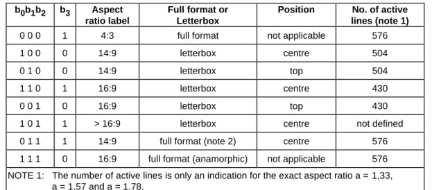
b0, b1, b2: shall denote the aspect ratio label, the letterbox format and position according to table 2. b3: shall denote the odd parity of b0, b1, b2, b3 according to table 2.
Table 2: Aspect ratio label, letterbox and position code b0b1b2 b3 Aspect
ratio label
Full format or Letterbox
Position No. of active
lines (note 1)
0 0 0 1 4:3 full format not applicable 576 1 0 0 0 14:9 letterbox centre 504 0 1 0 0 14:9 letterbox top 504 1 1 0 1 16:9 letterbox centre 430 0 0 1 0 16:9 letterbox top 430 1 0 1 1 > 16:9 letterbox centre not defined 0 1 1 1 14:9 full format (note 2) centre 576 1 1 1 0 16:9 full format (anamorphic) not applicable 576 NOTE 1: The number of active lines is only an indication for the exact aspect ratio a =1,33,
a = 1,57 and a = 1,78.
NOTE 2: The actual transmitted aspect ratio is 4:3, but a 14:9 centre window should contain all the relevant picture content to encourage a wide screen display on a 16:9 television set.
The aspect ratio label indicates a range of possible aspect ratio. All aspect ratio's falling in these ranges shall be labelled by the same code. Table 3 indicates the aspect ratio ranges.
Table 3: Aspect ratio ranges
Aspect ratio label Aspect ratio range Active lines
4:3 a ≤ 1,46 527 to 576 14:9 1,46 < a ≤ 1,66 463 to 526 16:9 1,66 < a ≤ 1,90 405 to 462 > 16:9 a > 1,90 < 405
4.2.2
Data group 2, enhanced services
4.2.2.1
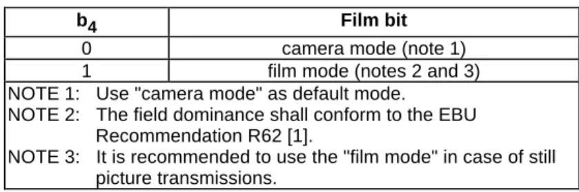
Film bit
b4: shall denote the film bit in accordance with table 4.
Table 4: Film bit
b4 Film bit
0 camera mode (note 1) 1 film mode (notes 2 and 3) NOTE 1: Use "camera mode" as default mode.
NOTE 2: The field dominance shall conform to the EBU Recommendation R62 [1].
NOTE 3: It is recommended to use the "film mode" in case of still picture transmissions.
4.2.2.2
Colour coding bit
b5: shall denote the colour coding bit in accordance with table 5.
Table 5: Colour coding bit
b5 Colour coding bit
0 standard coding
1 Motion Adaptive Colour Plus (note) NOTE: In film mode (bit b4 = 1), Motion Adaptive Colour Plus is
set to "fixed" Colour Plus operation, i.e. it is not motion adaptive.
4.2.2.3
Helper bit
b6: shall denote the helper bit in accordance with table 6.
Table 6: Helper bit
b6 Helper bit
0 No helper
1 Modulated helper (note) NOTE: A helper signal may be present only when the aspect
ratio label is either "16:9 letterbox centre" or "> 16:9 letterbox centre" and the number of active lines ≤ 430 lines.
4.2.2.4
Bit b
74.2.3
Data group 3, subtitles
4.2.3.1
Subtitles within Teletext bit
b8: shall denote the subtitles within Teletext bit in accordance with table 7.
Table 7: Subtitles within Teletext bit b8 Subtitles within Teletext bit
0 no subtitles within Teletext 1 subtitles within Teletext
4.2.3.2
Subtitling mode
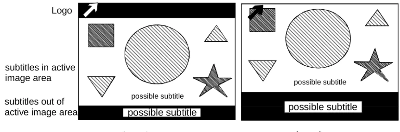
b9, b10: shall denote the mode of subtitling in accordance with table 8.
Table 8: Subtitling mode
b9 b10 subtitles in/out of active image area
0 0 no open subtitles 1 0 subtitles in active image area 0 1 subtitles out of active image area
1 1 reserved
NOTE: The "out of active image area" subtitling, which extends into the active image area shall be treated as "out of active image area".
Figure 3 indicates the meaning of the terms "in active image area" and "out of active image area".
Logo
subtitles in active image area subtitles out of active image area
possible subtitle
possible subtitle possible subtitle
possible subtitle
letterbox top
letterbox center
Figure 3: Examples of letterbox signals with logos and subtitling
4.2.4
Data group 4, others
4.2.4.1
Surround sound bit
b11: shall denote the surround sound bit in accordance with table 9.
Table 9: Surround sound bit
b11 Surround sound bit
0 no surround sound information 1 surround sound mode
4.2.4.2
Copyright information
b12, b13: shall denote the copyright bit and generation bit in accordance with table 10.
Table 10: Copyright information
b12 Copyright bit
0 no copyright asserted or status unknown 1 copyright asserted
b13 Generation bit
0 copying not restricted 1 copying restricted
Annex A (informative):
Rules of operation
A.1
Receiver display formats
To ensure automatic selection of the most appropriate display mode, the receiver with a 16:9 display should comply with the following minimum requirements:
Table A.1: Aspect ratio minimum requirements
b0b1b2 Aspect ratio label Minimum requirements
0 0 0 4:3 case 1
1 0 0 14:9 case 2
0 1 0 14:9 case 2
1 1 0 16:9 case 3
0 0 1 16:9 case 3
1 0 1 > 16:9 case 4
Case 1: 4:3 Full format: The 4:3 aspect ratio picture should be displayed centred with black bars at the left and right hand side of the display.
Case 2: Letterbox signalled as 14:9: the 14:9 aspect ratio picture should be displayed using one of the following two methods:
a) the 14:9 aspect ratio picture should be displayed centred with small bars at the left and right hand sides of the display;
b) the 14:9 picture may be displayed filling the full width of the visible screen by incorporating a small horizontal geometrical error, typically 8 %.
Case 3: Letterbox signalled as 16:9: the 16:9 aspect ratio picture should be displayed using the full width of the screen.
Case 4: Letterbox signalled as > 16:9: the > 16:9 aspect ratio picture should be displayed using one of the following two methods:
a) as under case 3;
b) the > 16:9 picture may be displayed using the full height of the screen, by further zooming in. It should be noted that the viewer should be free to override the automatically selected display condition. The speed of the automatic change of aspect ratio is limited mainly by the response time of the deflection circuit.
A.2
Subtitling
When the subtitling of letterboxed pictures is in, or partly in the "out-of active image area", the new 16:9 receivers will lose this information, unless they display the picture in the 4:3 mode. This would mean that on the 16:9 receiver, black bars would be present all around the active image content and this should be avoided.
To serve both the interests of the existing 4:3 and the new 16:9 viewers, it is of great importance, that:
- wide screen programmes should always have the subtitling (whether "in active image area" or "out of active image area") conveyed as well by means of the Teletext service;
- new 16:9 receivers, complying with the present document, should be equipped with a Teletext decoder and always have the possibility of detecting the Teletext presence bit b8.
A.3
Procedure in absence of signalling
Annex B (informative):
Recommendations
B.1
Low pass pre-filtering
It is recommended that the received status bit is low pass filtered before decoding.
This low pass filter should preserve the main spectral energy of the status bits signal, which resides in the spectral domain of 0 MHz up to 1,67 MHz.
B.2
Response time on a change in the received signalling
information
Annex C (informative):
Guidelines
C.1
Copyright information
The setting of data bit b13 to "0" does not mean that there are no constraints on the use of the programme material if copied
(as is the case in the absence of signalling bits).
History
Document history
Edition 1 November 1994 Publication as ETS 300 294 Edition 2 May 1996 Publication as ETS 300 294 Edition 3 September 1997 Publication as ETS 300 294 V1.3.2 April 1998 Publication
ISBN 2-7437-2104-9 Dépôt légal : Avril 1998