FUNDAMENTAL UNDERSTANDING OF A HIGH PERFORMANCE POLYMER FOR ORGANIC PHOTOVOLTAICS AND NEW MATERIAL DEVELOPMENT
BY RATIONAL MOLECULAR ENGINEERING
Wentao Li
A dissertation submitted to the faculty of the University of North Carolina at Chapel Hill in partial fulfillment of the requirements for the degree of Doctor of Philosophy
in the Department of Chemistry.
Chapel Hill 2015
ii © 2015 Wentao Li
iii ABSTRACT
Wentao Li: Fundamental Understanding of a High Performance Polymer for Organic Photovoltaics and New Material Development by Rational Molecular Engineering
(Under the direction of Wei You)
Organic photovoltaics are a promising renewable energy technology. Development of novel materials and device architecture for further enhancing their efficiency requires fundamental understanding of the impact of chemical structures on photovoltaic propert ies. Given that device characteristics depend on many parameters, deriving structure-property relationships has been very challenging.
Among many high performance polymers for organic photovoltaics, poly(benzodithiophene-alt-dithienyl difluorobenzotriazole) (PBnDT-FTAZ) is a very special one, due to its extremely efficient conversion of photons to observed current density. Although its absorption range is narrow with a band gap of ~ 2.0 eV, the power conversion efficiency of its bulk heterojunction solar cell based on phenyl-C61-butyric acid methyl ester (PC61BM) breaches
7%. In this dissertation, we conclude two fundamental reasons to account for the exceptional device performance of PBnDT-FTAZ by comprehensive investigation into morphology and device physics. On one hand, the molecular weight determines the morphology in the non-crystalline region. An appropriate molecular weight helps to achieve a small domain size, thus a shorter exciton diffusion path together with larger interfacial areas in the PBnDT-FTAZ:PC61BM
iv
improved hole mobility, which reduces bimo lecular recombination and directly accounts for the observed high fill factor in the OPV device. Overall, two important structure-property relationships regarding the molecular weight and the degree of fluorination of PBnDT-FTAZ are elucidated.
v
ACKNOWLEDGEMENTS
First and foremost, I would like to thank my advisor, Professor We i You, for his incredible patience during my graduate research. When I started to synthesize PBnDT-FTAZ on May 3rd, 2011, neither of us anticipated that I would have to spend 700 days to fully reproduce a
polymerization result. During this long puzzle solving process, Wei never even complained. Instead, he stayed focused on the underlying scientific questions and constantly provided me with numerous useful tips. I am truly grateful to Wei’s invaluable mentoring in regard to research methodology, experiment, presentation and writing over past five years. His work ethic will always inspire me to be a diligent and devoted researcher.
vi
I thank Professor Maurice Brookhart, Professor James Cahoon, Professor David Nicewicz, and Professor Jeffery Johnson for serving on my final defense committee. I also acknowledge Professor Valery Ashby for her previous committee work in my preliminary defense.
I want to thank my undergraduate research advisor, Professor Weidong He, at University of Science and Technology of China, for generously providing me an individual research project and kindly tolerating my destructions in his office and lab. His knowledge in living polymerization and polymer physics fostered my strong interest in polymeric materials.
Many thanks to my friends in Class 2010, UNC Chemistry, my past and previous You group colleagues, friendly staffs inside/outside of the Department of Chemistry, a nd all my other friends at Chapel Hill, for helping me to adapt myself into a new country and new culture quickly and comfortably. Many heartwarming details definitely make my experience at UNC memorable, and will always remind me to be a considerate person.
vii
TABLE OF CONTENTS
LIST OF TABLES ... xi
LIST OF FIGURES ... xii
LIST OF SCHEMES AND CHARTS ... xv
LIST OF EQUATIONS ... xvi
LIST OF ABBREVIATIONS AND SYMBOLS ... xvii
CHAPTER 1 INTRODUCTION TO ORGANIC PHOTOVOLTAICS ... 1
1.1 Performance parameters of photovo ltaics... 3
1.2 Device structure of an organic solar cell... 5
1.3 Working mechanism of organic photovoltaics ... 6
1.3.1 Exciton generation ... 7
1.3.2 Charge separation... 8
1.3.3 Charge transport ... 10
1.3.4 Charge collection ... 11
1.4 General design rules of polymers for organic photovoltaics ... 12
viii CHAPTER 2
CONTRASTING N-ALKYLATION SELECTIVITIES OF BENZOTRIAZOLE IN
THF AND DMF... 18
2.1 Introduction ... 18
2.2 Optimization of N2-alkylation yield ... 20
2.3 Opposite N-selectivity in THF and DMF ... 22
2.4 Ion aggregate postulation ... 24
2.5 Optimization of N1-alkylation yield ... 26
2.6 Conclusion ... 27
CHAPTER 3 CONTROLLING MOLECULAR WEIGHT OF PBNDT-FTAZ AND UNDERSTANDING ITS SIGNIFICANT IMPACT ON PHOTOVOLTAIC PROPERTIES ... 28
3.1 Introduction ... 28
3.2 Stoichiometry in polymerization... 29
3.3 Photovoltaic performance and electrochemical properties ... 33
3.4 Morphology impact of polymer molecular weight ... 37
3.5 Discussion and conclusion ... 43
3.7 Experimental Section ... 45
ix
4.1 Introduction ... 47
4.2 Design and synthesis of PBnDT-(X)TAZ... 50
4.3 Photovoltaic device performance... 55
4.4 Morphology and Molecular Texture ... 57
4.5 Factors Influencing Fill Factor... 61
4.8 Experimental Section ... 73
CHAPTER 5 A GENERAL APPROACH TOWARDS ELECTRON DEFICIENT TRIAZOLE UNITS TO CONSTRUCT CONJUGATED POLYMERS FOR SOLAR CELLS... 76
5.1 Introduction ... 76
5.2 Synthesis and discussion ... 80
5.3 Optical and electrochemical properties... 92
5.4 Photovoltaic Device Performance... 95
5.5 Conclusion ... 99
CHAPTER 6 CONCLUSIONS AND FUTURE DIRECTIONS ... 101
6.1 Conclusions ... 101
6.2 Future directions ... 103
6.2.1 Polydispersity effect... 103
x
6.2.3 Enriching triazole acceptor library... 105
6.2.4 Bridging the gap between small molecules and polymers ... 107
6.2.5 Future directions in OPV field ... 108
APPENDIX I: GEN ERAL METHODS ... 113
APPENDIX II: DETERMINING N-ALKYLATION SELECTIVITY OF BEN ZOTRIAZOLE BY 1H-NMR SPECTRA IN CHAPTER 2 ... 117
APPENDIX III: NMR SPECTRA OF INTERMEDIATES, MONOMERS AND POLYMERS IN CHAPTER 5 ... 134
xi
LIST OF TABLES
Table 2.1 Effect of solvent and temperature on yield and selectivity………21
Table 2.2 Effect of alkyl and leaving group on selectivity………22
Table 2.3 Solvent effect on N2-selectivity……….23
Table 2.4 Crown ether effect on alkylation N2-selectivity………26
Table 2.5 N2-selectivity and conversion in a series of THF/DMF mixed solvents………...27
Table 3.1 Controlling the molecular weight of PBnDT-FTAZ via tuning stoichiometric ratio………32
Table 3.2 Average photovoltaic performance and hole mobility of PBnDT-FTAZ:PC61BM devices with different molecular weights……….……..34
Table 3.3 Polymerization yields and energy levels[a] of PBnDT-FTAZ polymers based on different molecular weights……….…………...36
Table 3.4 Relative composition variations, domain spacing and anisotropy measured by R-SoXS along with power conversion efficiency………..38
Table 4.1 PBnDT-(X)TAZ: chemical composition, molecular weight and photovoltaic device properties………53
Table 4.2 Estimated HOMO energy levels according to CV measurement………..55
Table 5.1 Molecular weight and dispersity, absorption onset and energy levels of PBnDT-TAZ polymers…..………93
Table 5.2 Highest performance of four triazole-based polymers with PEDOT:PSS as hole transport layer………96
Table 5.3 Active Layer thickness, photovoltaic performance and hole mobility of TAZ polymers………....96
xii
LIST OF FIGURES
Figure 1.1 J-V curve of an organic solar cell with performance parameters……….4
Figure 1.2 Schematic illustration of a typical organic solar cell in normal architecture……...5
Figure 1.3 Schematic illustration of bulk heterojunction active layer in an organic solar cell with charge transport channel depicted……….………6
Figure 1.4 Working mechanism of BHJ organic solar cell: four steps of charge transfer process………..7
Figure 1.5 Chemical structures of PBnDT-HTAZ and PBnDT-FTAZ, and their OPV performance in BHJ solar cells with PC61BM………...16
Figure 1.6 Contour plot of calculated efficiency as a function of band gap and LUMO level based on Scahrber’s model………17
Figure 3.1 Correlation of actual Mn measured by GPC and calculated Mn by the Carothers Equation...32
Figure 3.2 (a) Current density vs. voltage curves and (b) Incident photon to current efficiency (IPCE) curves of PBnDT-FTAZ: PC61BM devices with molecular weight ranging from 10 kg/mol to 60 kg/mol………....34
Figure 3.3 UV-visible absorption spectra of pure polymers in dichlorobenzene solution (left) and pure polymer film on glass substrate (right)...35
Figure 3.4 UV-visible absorption spectra of the polymer:PC61BM blends (i.e., the active layers) on glass/ITO/PEDOT:PSS substrates………...….36
Figure 3.5 (a) GIWAXS out-of-plane and in-plane 20° sector averages along with circular averaged data of the five blend films. (b) Lorentz corrected R-SoXS scattering profiles for 284.1 eV for the five blend films………39
Figure 3.6 Two dimensional (2D) GIWAXS data for blend polymer films and neat polymer films of five polymers………..………46
Figure 3.7 (a) 2-D R-SoXS scattering data for the 40k polymer based blend film. (b) Perpendicular and parallel sector averages with respect to electric field polarization for all blend samples………..46
Figure 4.1 GPC Curves of PBnDT-(X)TAZ polymers………...53
Figure 4.2 UV-Vis absorption of PBnDT-(X)TAZ polymers in thin films………54
xiii
Figure 4.4 (a) J-V curves for the BHJ devices of ~350 nm thick films based on all five copolymers of PBnDT-(X)TAZ under 1 sun, AM 1.5G condition. (b) EQE for the same devices in (a). (c) The change of Jsc and Voc with increased
amount of F substitution. (d) The increase of fill factor tracks the increase of overall device efficiency as more F substituents are incorporated into the copolymer………..56 Figure 4.5 Field dependent EQE. EQE for different applied voltages ranging from +0.5V to -3V as indicated in the left plot………...57 Figure 4.6 (a) P-SoXS circular average profiles at 284.1 eV. (b) Sector averaged profiles
representing P-SoXS data perpendicular and parallel to the electric field
polarization………59 Figure 4.7 GIWAXS data of blend films on glass/ITO/PEDOT:PSS device substrates …....61 Figure 4.8 Upper panel: the external generation efficiency (EGE) with offset for clarity
as a function of applied pre-bias measured with TDCF at excitation wavelength of 530 nm. Lower panel: The EQE measured at 530 nm and
normalized to – 2 V as function of voltage for all five blends………..64 Figure 4.9 (a) The measured number of collected charges (Qcoll) and the corresponding
bimolecular recombination (BMR) fit with increasing delay time between laser pulse and extraction voltage for the F50 sample at 0.7 V pre-bias. (b) The BMR coefficient deduced from BMR fits as shown in (a) at conditions close to the respective open circuit for all five blends………..66 Figure 4.10 Charge carrier mobilities of electrons and holes together with the effective
extraction mobility as a function of fluorine substitution………..68 Figure 4.11 BMR coefficient……….74 Figure 4.12 Hole mobility derived from the hole only device………..74 Figure 4.13 Carrier density and effective extraction mobility measured with BACE………..75 Figure 5.1 High N-2 selectivity shown in 1H-NMR of crude product of NH-1,2,3-triazole
alkylation. Methylene peaks are assigned to marked N-alkyl isomers and starting material………...………..91 Figure 5.2 Normalized film absorptions of PBnDT-TAZ polymers spun cast from their
o-dichlorobenzene (ODCB) solution; inset shows the color variations of their ODCB solution (0.15 mg/mL)………..94 Figure 5.3 Energy level diagram of PBnDT-TAZ polymers and PC61BM………....94
xiv
xv
LIST OF SCHEMES AND CHARTS
Scheme 2.1 Benzotriazole alkylation isomerism and characteristic NMR peaks…………...20 Scheme 3.1 Polymerization scheme of PBnDT-FTAZ……….29
Scheme 4.1 Synthesis of the set of PBnDT-(X)TAZ with various amount of F
substitution……….51 Chart 5.1 General Structure of Triazole Based Acceptors……….77 Scheme 5.1 Synthetic strategies of popular acceptor units for organic photovoltaics………..79 Scheme 5.2 Syntheses of three m-TAZ acceptors from a 1,4-diketone intermediate and
related PBnDT-TAZ polymers………..80 Scheme 6.1 Proposed molecules to enrich triazole acceptor library………...106
Scheme 6.2 ADMET polymerization of small molecules with photovoltaic perform……....107 Scheme 6.3 A representative polymer displaying dramatically enhanced OPV performance
xvi
LIST OF EQUATIONS
Equation 1.1………4
Equation 1.2………4
Equation 3.1………...30
xvii
LIST OF ABBREVIATIONS AND SYMBOLS
power conversion efficiency 𝐽𝑟𝑒𝑐 recombination current density BACE bias enhanced charge extraction
BG band gap
BHJ bulk heterojunction
BMR bimolecular recombination BnDT benzodithiophene
CNTAZ poly(benzodithiophene-alt-dithienyl benzotriazole-5,6-dicarbonitrile)
CT charge transfer CV cyclic voltammetry Đ polydispersity index DPP diketopyrrolopyrrole DTBT dithienyl benzothiadiazole
DTffBT difluorinated dithienyl benzothiadiazole DTPyT dithienyl thiadiazolopyridine
EGE external generation efficiency EQE external quantum efficiency
FF fill factor
FTAZ difluoro benzotriazole
GIWAXS grazing incidence wide angle X-ray scattering GPC gel permeation chromatography
GRIM Grignard metathesis HMPA hexamethylphosphoramide
HOMO highest occupied molecular orbital HTL hole transport layer
xviii
IPCE incident photon to current efficiency ITO indium tin oxide
Jsc short circuit current density
LUMO lowest unoccupied molecular orbital Mn number average molecular weight MPP maximum power point
MW molecular weight
Mw weight average molecular weight NBS N-bromosuccinimide
NGR non-geminate recombination NMR nuclear magnetic resonance ODCB o-dichlorobenzene
OFET organic field-effect transistor OPV organic photovoltaics
p polymerization degree P3HT poly(3-hexyl thiophene)
PBnDT-FTAZ poly(benzidithiophene-alt-difluoro dithienyl benzotriazole) PBnDT-HTAZ poly(benzidithiophene-alt- dithienyl benzotriazole)
PC61BM phenyl-C61-butyric acid methyl ester
PCE power conversion efficiency
PEDOT:PSS poly(3,4-ethylenedioxythiophene) poly(styrenesulfonate) PrzTAZ poly(benzodithiophene-alt-dithenyl triazolopyridazine) P-SoXS polarized resonance soft X-ray scattering
PyCNTAZ poly(benzodithiophene-alt-dithenyl 6-cyano triazolopyridine) Qcoll amount of collected charges after delay
Qpre amount of charges collected during delay
Qtot amount of extractable charges
xix RPM round per minute
RSoXS resonance soft X-ray scattering SCLC space charge limited current
STXM scanning transmission X-ray microscopy TA transient absorption
TAZ benzotriazole
TDCF time-delayed collection field TPD thienopyrrolodione
TSI total scattering intensity
Vcoll collection bias
Voc open circuit voltage
Vpre prebias during short laser pulse before charge collection
𝑑 film thickness
𝑒 elementary charge
1 CHAPTER 1
INTRODUCTION TO ORGANIC PHOTOVOLTAICS
Sustaining and advancing human civilization has been heavily relying on massive consumption of fossil fuels since the Industrial Revolution. For instance, the annual coal consumption in the United States rapidly increased from 0.2 quadrillion British thermal unit (Btu) in 1850 to 15.5 quadrillion Btu in 1920, and coal has remained as one of the primary energy sources thereafter.1 Fossil fuels certainly have many advantages as the energy source: they are
readily available from coal mines or oil fields, easy to be transported at low cost, and able to produce large amount of energy upon combustion. However, two severe issues concerning the massive usage of fossil fuels have emerged after decades of combustion of coal, oil and natural gas. First, it takes millions of years for buried organic materials to be converted into combustible fossil fuels; therefore, in a foreseeable future, fossil fuel is a non-renewable energy source. In fact, it is estimated that coal would be the only remaining fossil fuel after 2042, which could also be completely depleted another 70 years later.2 Second, the combustion of fossil fuels ge nerates
large amounts of carbon dioxide, a greenhouse gas that significantly contributes to global warming, and multiple air pollutants including nitrogen oxides, sulfur oxides and particulates. For all these reasons, a transition from these fossil fuels to renewable and environmentally benign energy sources is rather a must than an option.
2
the Earth, the Sun provides infinite energy supply through continuous light radiation in the daytime. By directly converting sunlight into electricity, solar panels do not generate any waste; these solar cells do not have moving parts to convert light into electricity, thus they are noise-free. Moreover, the manufacturing cost for mainstream solar panels (e.g., Si, CdSe, and CIGS) has been continuously falling down; combined with the installation cost, the total cost for producing the electricity with these solar cells have been rapidly approaching the “grid parity”. Well-developed, residential- use solar panels are already available from solar panel distributers, and have been adopted by numerous homes across the globe.
Issues remain, though. Take Si solar cells for example. After years of research and development, Si solar cells have reached very high power conversion efficiency in the lab (~25%);3 however, some significant drawbacks still hinder the wider application of Si solar cells.
First, the manufacturing process of a monocrystalline Si solar cell requires much energy input, for example, melting polycrystalline silicon at 1425 °C. As a result, the Si solar cell’ energy payback time, i.e., the time a photovoltaic system needs to generate the same amount of energy that was consumed during its manufacturing, is one of the longest among all photovoltaic technologies.4 Second, the manufacturing process of Si photovoltaic panels generates undesirable
wastes, including particulates, silicon waste solid, and other hazardous chemicals. Third, a monocrystalline Si solar cell is extremely brittle. They are very sensitive to mechanical constraints, which puts some limits on where these Si cells can be used, and also introduces additional failure mechanism (e.g., broken cells).
3
polymers (and small molecules) is expected to cut down both manufacturing costs and generated waste. By taking advantage of good solubility of structurally tailored polymers, the active layer in OPV devices can be solution-processed; furthermore, large-area films can be easily prepared by casting this solution onto substrates in a roll-to-roll fashion, effectively reducing the fabrication cost. Paired with a soft substrate and mechanically robust electrodes, the entire photovoltaic device incorporating a polymer thin film can be flexible, expanding the application of such OPV devices in new areas, for example, wearable electronics.
However, compared with well-studied Si photovoltaics, OPV devices usually exhibit a much less competitive efficiency (~6% at sub-module level), and many fundamental questions remain to be answered. This chapter will briefly introduce performance parameters of a photovoltaic device (OPV included) and the basic device structure of an organic solar cell. The working mechanism of OPV will be next discussed, together with the electrochemical and morphological requirements for conjugated polymers to be used in the OPV device. After a summary of the design rules of conjugated polymers for OPV, this chapter will be finished by introducing a special conjugated polymer that has unique and intriguing properties.
1.1 Performance parameters of photovoltaics
The power conversion efficiency (i.e., PCE, or ) of all solar cells, regardless of the working component (i.e., Si, CdSe, CIGS, or organics), is determined by three parameters: the open circuit voltage (Voc), the short circuit current (Jsc) and the fill factor (FF).
Voc and Jsc are the maximum output voltage and current that a solar cell is able to produce,
4
and there exists a maximum power point (MPP) on current density vs. voltage curve (J-V curve).
The efficiency is defined as the ratio of the maximum power output to the solar power input (equation 1.1), and the FF is defined as the ratio of the maximum power output to the product of Voc and Jsc (equation 1.2), i.e., the area ratio between two rectangles in Figure 1.1.5
𝜂 = 𝑃𝑚𝑎𝑥
𝑃𝑖𝑛 =
𝐽𝑠𝑐∙𝑉𝑜𝑐∙𝐹𝐹
𝑃𝑖𝑛 (1.1)
𝐹𝐹 = 𝑃𝑚𝑎𝑥
𝐽𝑠𝑐∙𝑉𝑜𝑐 (1.2)
Figure 1.1 A representative J-V curve of an organic solar cell with performance parameters. (Adapted from reference 3.)
In organic solar cells, the relationship among these three parameters (Jsc, Voc and FF) are
5
performance, and attempt to introduce some independent structure-property relationships of conjugated polymers used in OPV devices.
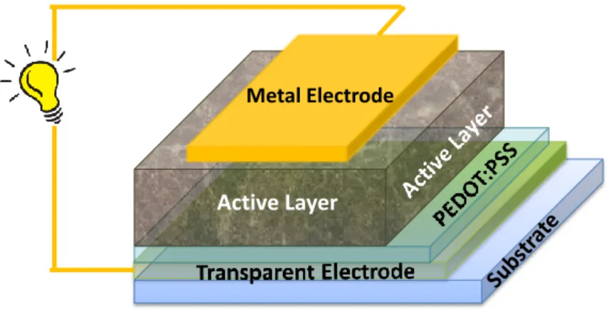
1.2 Device structure of an organic solar cell
In a normal device architecture (vs. inverted device architecture), an organic solar cell has its charge generation part, i.e., the active layer, sandwiched between the anode (e.g., transparent indium tin oxide (ITO)) and the cathode (e.g., calcium/aluminum double metal layer) (Figure 1.2).6 Bearing different work functions, these two electrodes form a built- in electrical field to
provide driving force for charge carriers generated in the active layer to the right electrode. In most cases, a layer of poly(3,4-ethylenedioxythiophene) poly(styrenesulfonate) (PEDOT:PSS) is applied between ITO and the active layer to adjust the work function of anode for better hole transport. Recently, some optional electron transport layers (ETL) were also developed to be applied between the cathode and the active layer, with functions similar to that of PEDOT:PSS layer.7
Figure 1.2 Schematic illustration of a typical organic solar cell in conventional architecture. (Reprinted from reference 7 with permission. Copyright 2012 American Chemical Society)
Metal Electrode
6
The active layer, where the sunlight is converted to electricity, directly determines the performance of organic photovoltaics. The most effective active layer configuration so far is bulk heterojunction (BHJ), which is essentially a physical blend of p-type, electron-donating organic semiconductors, i.e., conjugated polymers, and n-type electron-accepting organic semiconductors, i.e., fullerenes derivatives.8 These two components form an interpenetrating
network with large interfacial area between the polymer and the fullerene, and building hole/electron transport pathways at the same time. A schematic illustration of BHJ, in the context of a conventional device architecture, is shown in Figure 1.3.9 Therefore, it is crucial for BHJ
active layer to adopt a favorable morphology in order to achieve a high PCE.
Figure 1.3 Schematic illustration of bulk heterojunction active layer in an organic solar cell with charge transport channel depicted. (Reprinted from reference 9 with permission. Copyright 2008 Material Research Society)
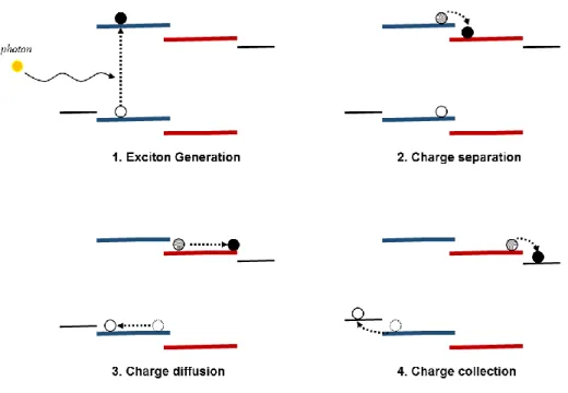
1.3 Working mechanism of organic photovoltaics
7
exciton generation, charge separation, charge diffusion, and charge collection (Figure 1.4). We will briefly describe the physical process, including possible losses, in each step, and derive corresponding requirements for polymer and BHJ morphology to facilitate different charge transfer processes at various interfaces and length scales.
Figure 1.4 Working mechanism of BHJ organic solar cell: Four steps of charge transfer process.
1.3.1 Exciton generation
8
polymers in the following discussion. Depending on the energy of incident photon, the electron can be excited to different states, but most of them will finally thermalize to the lowest unoccupied molecular orbital (LUMO) to form a Coulomb ically bound electron and hole pair, with the electron on the LUMO and the hole on the HOMO. This electron/hole pair is usually referred to as the exciton.
Because excitons are only generated by those incident photons with the wavelength smaller than the absorption onset of polymer, a more red-shifted absorption profile of polymer would thus utilize a wider range of the sunlight, and could in principle generate more excitons for subsequent steps. Thus, a small band gap is usually desirable for polymers to absorb more sunlight and to maximize the exciton generation.
However, an inevitable loss mechanism exists in this exciton generation step: excited electrons have to thermalize to the LUMO level to form excitons. This means that the extra energy that is greater than the band gap of the polymer will be released as the thermal energy. This thermalization loss accounts for the most energy loss in a single junction solar cell. Together with the absorption loss from un- utilized photons that have less energy than the band gap of the polymer, this thermalization loss largely sets the Shockley-Queisser limit of a single junction solar cell to 33%.10
1.3.2 Charge separation
The generated excitons on polymers will then diffuse to the p-n junction interface, i.e., the interface between p-type polymers and n-type fullerene derivatives (usually phenyl-C61-butyric acid methyl ester (PC61BM), to form a charge transfer state. The LUMO offset between
9
within the charge transfer state, and facilitates the electron transfer from polymer’s LUMO to fullerene’s LUMO, leaving the hole still on polymer’s HOMO and forming a charge separation state.
In this step, the exciton generated by light absorption is converted into one free electron on PC61BM and one free hole on polymer. Since this is the key step converting absorbed sunlight
into free charges, it is crucial for organic solar cells to optimize this step to achieve high efficiency. Five requirements are usually considered to promote this charge separation step.
1) Since the exciton diffusion length is believed to be around 10 nm,11 a proper domain
size with an average diameter of 20 – 30 nm would be favorable for the excitons to survive from the diffusion process. Recent experimental results also indicate that a smaller domain size effectively enhances the charge separation efficiency (and overall efficiency) even though the energy levels and band gap of the conjugated polymer are not ideal.12
2) The polymer and PC61BM must be well intermixed to form sufficient interfacial areas
in order to ensure high probability of charge separation. Ideally, the miscibility between polymer and PC61BM should be high enough to form enough interfacial area for exciton to split, but also
low enough to form pure domains for charge transport (vide infra).
3) At the polymer:PC61BM interface, polymer backbone should be facing the fullerene
with its π-plane (“face-on”) instead of interacting the fullerene with the edge of backbone (“edge-on”) or with the polymer chain end (“end-on”). This “face-on” conformation has been experimentally proved to benefit the exciton splitting at the molecular interface.13
4) According the Marcus theory, the LUMO offset between polymer and PC61BM
10
appropriate LUMO-LUMO pairing between the polymer and the fullerene derivative is necessary to achieve a high efficiency of charge separation.14 It is usually accepted that a
minimum LUMO offset of 0.3 eV is needed to ensure exciton splitting.15
5) A partial charge-separated state on the polymer would be helpful to promote the exciton to fully split at the interface. Most often, a strong dipole pointing from the electron-rich unit to the electron-deficient unit of the polymer backbone helps to form a partial charge-separated state, and fluorination at the latter position is proved to be effective in increasing this dipole moment.16,17 Correspondingly, the PC
61BM should be adjacent to the electron-deficient
unit of the polymer backbone, such that the partially separated electrons can be readily accepted by PC61BM. On the contrary, when the electron-deficient unit is hindered from PC61BM by
bulky side chains, the charge separation efficiency would drop.18
Efficiency loss in this charge separation step mainly comes from the geminate recombination between unseparated electron and hole pairs (i.e., the charge transfer state can relax back to the ground state). Nevertheless, geminate recombination is still being actively investigated. Fortunately, the loss due to geminate recombination is often negligible when compared with the thermalization loss (vide supra) and the non- geminate recombination loss (vide infra); therefore the geminate recombination loss will not be further discussed in following chapters.
1.3.3 Charge transport
Under the built- in field, separated electrons and holes can transport from the polymer:PC61BM interface to the cathode and anode, respectively. Naturally, a comparable
11
In most cases, because PC61BM domain is more crystalline than the polymer domain, the
electron mobility is faster than the hole mobility. Therefore, the hole mobility typically becomes the limiting factor. The hole mobility in the BHJ blend includes three components: 1) hole transport along the polymer backbone; 2) hole transport among adjacent π planes in the same polymer domain; 3) hole transport between adjacent polymer domains. Therefore, to improve the hole mobility requires close π- π stacking of polymer backbone, pristine crystalline domain of polymers, and good connectivity among crystalline domains.
The third major loss mechanism of OPV, non-geminate recombination, other than the thermalization loss and light absorption loss, occurs in the charge transport step. When the charge transport is not efficient enough to remove all separated charges, for example, due to a low hole mobility, free electrons and holes could accumulate in each domain and recombine at the polymer:PC61BM interface. A bimolecular recombination model is usually applied to
simplify the non-geminate recombination process, in which the recombination current density is proportional to the square of charge carrier density under steady state.20
1.3.4 Charge collection
The end of the light-to-electricity process involves the free electrons and holes being collected by the cathode and anode, respectively. Thus, a proper energy level matching between polymer and the anode, and that between the fullerene and the cathode, are required to minimize the loss during the charge collection. Similarly to the charge separation step, a “face-on” orientation of polymer backbone to the electrode and a strong dipole at the electrode interface21
12
1.4 General design rules of polymers for organic photovoltaics
Given the specific working mechanism of OPV as discussed above, we can conclude the general design rules of conjugated polymers to achieve highly efficient organic solar cells. Please note that as the understanding o f OPV working mechanism has been gradually deepened in the past two decades, the design rationale of polymers has also been continuously improved over the time. Thus we try to summarize the design rationale of conjugated polymers for BHJ solar cells from a historical perspective.
1) Recognizing the limited light absorption of poly(3-hexylthiophene) (P3HT) due to its band gap of 1.9 eV, the community initially focused on designing new conjugated polymers to extend the absorption range of P3HT. This was done by introducing the concept of “donor-acceptor” (D-A) alternating copolymers, i.e., electron-rich moiety and electron-deficient moiety alternatively bound along the conjugated polymer backbone. This design strategy was to directly address the first step in the working mechanism of OPV: exciton generation. N umerous low band gap D-A polymers were synthesized to absorb more incident lights, and to further improve Jsc.
On the other hand, Voc is mainly determined by the energy difference between free
electrons and holes, which depends on the difference between PC61BM’s LUMO level and
polymer’s HOMO level. Therefore, a high Voc would require a deep HOMO level of the polymer.
However, further lowering the HOMO level of the polymer would lead to a larger band gap, which would diminish the light absorbing ability of the polymer. Therefore, a trade-off exists: a deep HOMO is preferable to achieve a high Voc, but the Jsc would be “sacrificed” due to a large
band gap; on the other hand, a high HOMO would lead to a smaller band gap, benefiting Jsc, but
13
trade-off, indicating that there exists an optimal HOMO level that could strike a balance between Jsc and Voc to maximize the efficiency of organic solar cells.15 Thereafter, much effort was made
to synthesize polymers that would target the optimal HOMO and LUMO levels.
Perhaps the most noteworthy D-A polymers that were able to achieve high energy conversion efficiency numbers were the PTB series, first published by Luping Yu’s group in 2009.22 Soon after, benefiting from previous establishments in the chemical structure-band gap
correlation of conjugated polymers,23 many high-performing D-A polymers with desirable
energy levels and band gaps were synthesized from 2009 to 2011, reaching efficiency numbers of 6%-7%, including three contributions from our research group.24-26 Most of these polymers
were designed under the guidance of Scharber’s calculation.
2) Quite successful as Scharber’s model was, many “seemingly promising” polymers would turn out to be low performing, even these polymer fitted into the Scharber’s model very well. Some polymers, although possessing near-optimal energy levels and band gaps, generated poor current in their OPV device. Detailed investigation into these polymers usually revealed similar reasons: poor hole transport, either because of weak π- π stacking of polymers or an “edge-on” orientation of polymer backbones to the electrode. Thus, in the second stage of polymer design, the community focused on the hole transport properties of polymers, i.e., the charge transport step in the working mechanism of OPV, in addition to the Scharber’s model.
14
area within organic electronics: organic field-effect transistor (OFET). In fact, a number of building blocks, discovered in the OFET field, which were able to achieve high mobility have been adopted into the design of conjugated polymers for OPV.
3) More recently, the OPV community started to appreciate the importance of sub-mesoscale morphology in the BHJ active layer. Complimentary to GIWAXS, resonant soft X-ray scattering (RSoXS) reveals the morphology in weakly crystalline region by providing the scattering contrast on the 10 nm scale.27 RSoXS characterizes domain spacing and domain purity,
in addition to the backbone orientation at the polymer:PC61BM molecular interface. These
important parameters are closely related to the key step of the OPV working mechanism: charge separation. 28-31 On the other hand, time-resolved spectroscopy, especially transient absorption
(TA), sheds light on the charge separation kinetics on the femtosecond (fs) scale. The fate o f generated excitons at polymer:PC61BM interface can thus be tracked and compared with
hypothesized polymer design rationale. For example, the effect of dipole moment on charge separation has been investigated by TA.17
With a deeper understanding of the OPV operating mechanism, enabled by many new investigating tools, and the enriched structure-property relationships, designing conjugated polymers to achieve higher efficiencies of OPV devices becomes more complex and convoluted. In addition to the appropriate energy levels, band gap and a high hole mobility, the “ideal” polymers would also require favorable BHJ morphology, including minimal domain size, appropriate domain purity, “face-on” molecular orientation to PC61BM, docking position for
15 1.5 A unique polymer: PBnDT-FTAZ
In early 2011, our research group synthesized two structurally similar polymers for OPV (structures shown in Figure 1.5).32 Surprisingly, the fluorinated polymer introduced an all-around
improvement of Jsc, Voc, and FF. Although structurally, poly(benzodithiophene-alt-dithieno
difluorobenzotriazole) (PBnDT-FTAZ) merely replaced two hydrogen atoms in the repeating unit of poly(benzodithiophene-alt-dithieno benzotriazole) (PBnDT-HTAZ) with two fluorine atoms, the PCE of the former was significantly higher than that of the latter (7.1% vs. 4.4%), approaching the world-record high efficiency at the time.
Figure 1.5 Chemical structures of PBnDT-HTAZ and PBnDT-FTAZ, and their OPV performance in BHJ solar cells with PC61BM. (Reprinted from reference 32 with permission.
Copyright 2012 American Chemical Society.)
This high efficiency, especially the high Jsc, was unexpected, because the band gap of
16
current from its narrow absorption range became interesting. In addition, the high FF (over70%) of its OPV device was also very intriguing.
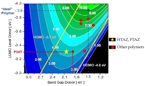
Interestingly, fluorination of PBnDT-HTAZ into PBnDT-FTAZ did not significantly change the HOMO and LUMO levels, according to the experimental results.32 In fact, if we fit
the LUMO level and the band gap of these two polymers into the Scharber’s model, the predicted efficiency of PBnDT-HTAZ actually matches well with the experimental result (Figure 1.6). Therefore, it is the fluorine substituent that would largely account for the drastic performance improvement for PBnDT-FTAZ.
Figure 1.6 Contour plot of calculated OPV efficiency as a function of band gap and LUMO level based on Scahrber’s model published in reference 13. PBnDT-HTAZ and PBnDT-HTAZ are labeled as yellow star while other high performing polymers are labeled as red dots.
17
18 CHAPTER 2
CONTRASTING N-ALKYLATION SELECTIVITIES OF BENZOTRIAZOLE IN THF
AND DMF
2.1 Introduction
The acceptor unit of PBnDT-FTAZ, benzotriazole, has been used as a unique building block in the design of donor-acceptor conjugated polymers since its first such application was reported in 2004.33 One notable feature of benzotriazole is that the necessary alkylation can
occur on the N2 position of the benzotriazole (i.e., N2-alkylation). Such a “centered” alkylation pattern not only helps to solubilize resulting polymers, but also minimizes the steric hindrance between adjacent repeat units. Therefore, a more planar conjugated backbone is usually obtained by benzotriazole, which is beneficial for charge transport (e.g., high mobility), a desirable feature for organic photovoltaics (OPV).32,34-38 PBnDT-FTAZ itself is a persuading example. The higher
19
However, the yield of the desirable N2-alkylation is typically low in reported syntheses,42-45 which significantly impedes efficient utilization of this unique building block. For
example, Katritzky et al. reported a method to noticeably improve the overall yield of N -alklyation of benzotriazole; however, the N2-alkylation observed by NMR was only to be 20% - 55%, depending upon the alkyl halide.45 In our original report of PBnDT-FTAZ, the yield of
N2-alkylating the 5,6-difluorobenzotriazole was only around 17%, severely limiting large-scale syntheses of this promising monomer (FTAZ) and related polymers.32 This low yield of
N2-alkylation is largely due to the fact that the inherent tautomerization of the benzotriazole leads to two competing alkylations (N1 vs. N2 in Scheme 1). To promote the N2- functionalization of benzotriazole, Reynolds et al. introduced steric hindrance such as bromine or thiophene on 4/7 position of the benzotriazole and effectively improved N2-selectivity.37 Alternatively, Shi et al.
discovered that reacting benzotriazole with an alcohol under standard Mitsunobu condition favors the formation of the kinetic product (N2-substitution).46 Successful as they are, these new
approaches either suffer from multi-step syntheses of specific substrates, or only show high N2-selectivity with a few sterically hindered alkyls. In this chapter, we describe our own optimization of the alkylation of benzotriazole. We discover that for this simple SN2 reaction, the
20 2.2 Optimization of N2-alkylation yield
In a typical benzotriazole alkylation via the SN2 mechanism, the triazole moiety is first
deprotonated by a base. The benzotriazole anion serves as the nucleophile to attack the substrate, e.g., primary alkyl bromides (Scheme 2.1). In this scenario the selectivity and yield of the alkylation are solely determined in the second step, an SN2 reaction. Therefore, our study was
focused on factors that govern the SN2 reaction, including solvent, temperature, leaving group
and the substrate (i.e., the alkyl chain). We used 1H-NMR spectra of the crude product after
careful work-up to determine the selectivity and to estima te the conversion of each reaction. Selectivity and conversion were calculated according to equation 2.1 and 2.2, respectively, based on the integration of characteristic methylene peaks corresponding to these two isomers (N1 vs. N2) and the residual alkyl bromide (Figure S1).
Scheme 2.1 Benzotriazole alkylation isomerism and characteristic NMR peaks
𝑁2 𝑠𝑒𝑙𝑒𝑐𝑡𝑖𝑣𝑖𝑡𝑦 = 𝐼𝑎
𝐼𝑎+𝐼𝑏 × 100% (2.1)
𝑐𝑜𝑛𝑣𝑒𝑟𝑠𝑖𝑜𝑛 = 1.2(𝐼𝑎+𝐼𝑏)
21
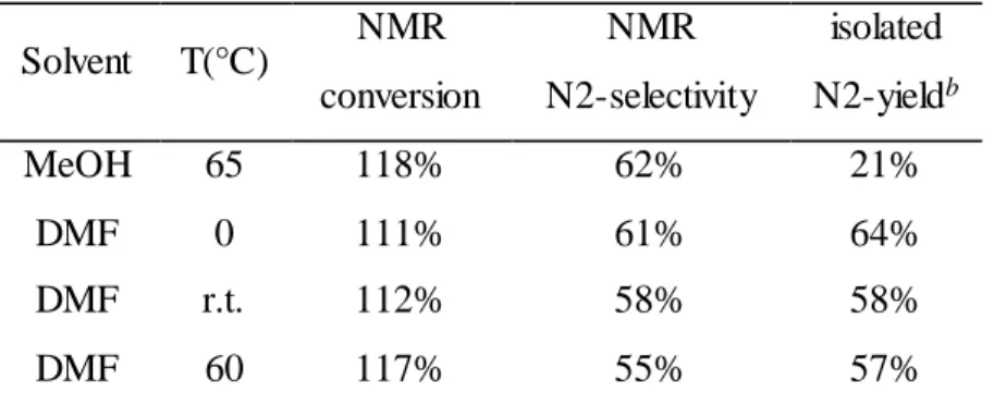
We first explored the effect of solvent and temperature, because they typically exert the most influence on the rate of the SN2 reaction. Methanol appeared to be the most popular solvent
in existing literature.42-44 However, the rate of S
N2 reaction is usually limited in protic solvents,
because the nucleophile is highly solvated via hydrogen bonding with protic solvent molecules. To improve the reaction rate (and the yield), we first attempted a common polar, aprotic solve nt, DMF. The isolated yield in methanol is as low as literature reported; however, the isolated yields in DMF are significantly improved (Table 2.1). Interestingly, both solvents (methanol and DMF) facilitate the formation of the product with little dependence on temperature (i.e., ~ 60% N2-selectivity in all studied cases). To summarize, a polar, aprotic solvent such as DMF greatly improves the yield of the alkylation of benzotrizole, with N-2 product being the dominant isomer. Also, a lower temperature appears to afford slightly higher yield of the N2 product. Finally, Table 2.1 shows that the isolated yield of the N2 isomer is very similar to the N2 selectivity estimated by 1H-NMR, which indicates the conversion calculated by 1H-NMR is a good estimate.
Therefore, we will use the co nversion and selectivity determined by 1H-NMR in the following
discussion for convenience without loss of meaningful comparison.
Table 2.1 Effect of solvent and temperature on yield and selectivity
Solvent T(°C) NMR conversion
NMR N2-selectivity
isolated N2-yieldb
MeOH 65 118% 62% 21%
DMF 0 111% 61% 64%
DMF r.t. 112% 58% 58%
DMF 60 117% 55% 57%
a The reactions were performed with 1 mmol benzotriazole, 1.2 mmol (20% excess) hexyl bromide and 2.0 mmol potassium carbonate in 40 mL of solvent.
22 2.3 Opposite N-selectivity in THF and DMF
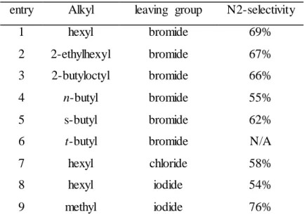
Table 2.2 summarizes the effect of leaving group and alkyl chain identity on the selectivity of this alkylation. As suggested by the previous discussion, all reactions were conducted in DMF at room temperature. First, no appreciable conversion was observed for the reaction with t-butyl bromide (entry 6), which supports the assumption that the alkylation proceeds via an SN2 mechanism. In general, both length and bulkiness of alkyl chains have
minimal effects on the N2- selectivity (entries 1 through 5). N2-selectivity is lower with chloride/iodide leaving groups (entries 7 and 8). However, one exception comes from methyl iodide (entry 9), where a noticeably higher N2-selectivity (76%) was observed.
Table 2.2 Effect of alkyl and leaving group on selectivitya
entry Alkyl leaving group N2-selectivity
1 hexyl bromide 69%
2 2-ethylhexyl bromide 67% 3 2-butyloctyl bromide 66%
4 n-butyl bromide 55%
5 s-butyl bromide 62%
6 t-butyl bromide N/A
7 hexyl chloride 58%
8 hexyl iodide 54%
9 methyl iodide 76%
23
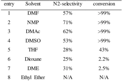
Attempting to further increase the yield and the N2-selectivity, we then investigated several common polar, aprotic solvents of various polarities. As shown in Table 2.3, similar N2-selctivity values around 70% were observed when solvents of similarly strong polarity as DMF were used, such as NMP and DMAc. Though DMSO is usually considered to be a more polar solvent than aforementioned ones, the alkylation with DMSO as the solvent does not show much N2-preference (vide infra). Surprisingly, for the reaction conducted in THF, a very low N2-selectivity (22%) was observed, together with a significantly low conversion. Interestingly, other ether solvents show similarly suppressed N2-selectivity. For example, the N2-selectivity for the reaction in dimethoxyethane is only 31%. When dioxane was adopted as the solvent, the N2-selectivity was even lower than that in THF. Additionally, no reaction was observed for ethyl ether as the solvent, since its low polarity does not favor the SN2 reaction.
Table 2.3 Solvent effect on N2-selectivitya
entry Solvent N2-selectivity conversion
1 DMF 57% >99%
2 NMP 71% >99%
3 DMAc 62% >99%
4 DMSO 53% >99%
5 THF 28% 43%
6 Dioxane 25% 2.2%
7 DME 31% 2.5%
8 Ethyl Ether N/A N/A
aThe reactions were performed with 1.0 mmol of benzotriazle, 1.2 mmol of hexyl bromide and 2.0 mmol of K2CO3 in 40 mL of solvent at r.t. N/A in selectivity denotes no product was
24 2.4 Ion aggregate postulation
This opposite selectivity of benzotriazole alkylation in THF vs. DMF is quite analogous to that of enolate alkylation where two competing reaction pathways also exist, O -alkylation and C-alkylation.47 When the enolate alkylation occurs in polar, aprotic solvents, such as
hexamethylphosphoramide (HMPA), the negative charge of enolate anion is mainly located on the oxygen. Thus O-alkylation dominates the reaction. However, when the same enolate alkylation is coducted in THF, the oxygen anion of enolate participates in the formation of ion aggregates, together with metal cations and solvent molecules. As a result, only α carbon is available for alkylation, leading to C-alkylation as the major reaction pathway. The structures of these enolate ion aggregates in THF have been well studied via UV-absorption and X-ray diffraction by Streitwieser et al.48-53 and Williard et al.,54-57 respectively. In addition, similar ion
aggregates formed by various molecules58-63 in other ether solvents have been reported.64
Herein we postulate that the observed different selectivity between N1-alkylation and N2-alkylation of benzotriazole in different solvents is also subject to this ion aggregate mechanism. We propose that in DMF and other polar, aprotic solvents, free benzotriazole anions are generated after complete deprotonation. Statistically, assuming equal charge densities at all three nitrogens, the ratio of N-2 anion vs. N-1 anion would be 1:2 (i.e., 33% probability of N-2 anion), which should lead to a 33% of N-2 selectivity. However, Table 2.3 shows the opposite: the N2-selectivity in DMF, NMP, and DMAc is typically above 65%. In fact, this preference of N2-product over N1-product for benzotriazole in polar, aprotic solvents is in good agreement with an earlier study on the tautomerism of 1,2,3-triazole, where Albert and Taylor predicted that the 2-H tautomer is preferred by a factor of two.65 It was believed that the 1-H tautomer would
25
Structurally similar to 1,2.3-triazole, the benzotriazole likely prefers the 2-H tautomer as well, which would lead to the dominance of anion in polar, aprotic solvents and explain the N2-selectivity around 67%.
On the other hand, in THF and other ether solvents, the deprotonated benzotriazole could form ion aggregates with potassium cations and ether molecules, similar to the formation of enolate based ion aggregates in THF. In this scenario, the formation of ion aggregates by the dominant N2-anion would leave the N1-position of the N2-anion for the alkylation, whereas the N1-anion incorporated into the ion aggregates would subject the N2-position to the alkylation. Therefore, this very likely formation of ion aggregates would essentially reverse the N2-selecivity observed in polar, aprotic solvents where “free” anions are prevalent. In addition, the reaction rate would significantly slow down because of the low polarity of ether solvents and the additional step of “breaking apart” these ion aggregates before forming the alkylated product. Thus low conversion was observed in these ether solvents.
While DMF and THF show clear regioselectivity, conducting the same reaction in DMSO does not particularly prefer N2- or N1-alkylation. This is likely because the oxygen atom in DMSO has more sp3 character than that in DMF and more sp2 character than that in THF. This
intermediate hybridization of oxygen in DMSO could result in only partial formation of ion aggregates. This partial formation of ion aggregates would not only explain the low selectivity in DMSO, but would also account for the higher conversion in DMSO than that in THF.
26
ion aggregates would dramatically decrease after adding a sufficient amount of 18-crown-6. As Table 2.4 shows, the 2-selectiviy from the alkylation in DMF changes little in the presence of 18-crown-6, suggesting that the crown ether does not affect the SN2 reaction. However in THF,
addition of crown ether increases the N2-selectivity from 22% to 45% and improves the conversion significantly, from 2.6% to 89% (see NMR spectra in SI). Both observations can be ascribed to the suppression of ion aggregate formation due to the sequestrat ion of free potassium cations with 18-crown-6.
Table 2.4 Crown ether effect on alkylation N2-selectivity a
Condition DMF THF
without 18-crown-6 68% 22% with 18-crown-6 64% 45%
a The reaction were performed with 1.0 mmol of benzotriazole, 1.2 mmol of hexyl bromide and 2.0 mmol of K2CO3 in 50 mL of solvent at r.t., with or without 2.0 mmol of 18-crown-6.
2.5 Optimization of N1-alkylation yield
27
Table 2.5 N2-selectivity and conversion in a series of THF/DMF mixed solvents a
DMF (V%) N2-selectivity Conversion
0 24% 10%
5 29% 62%
20 46% 113%
50 53% 113%
80 53% 114%
95 58% 111%
100 60% 115%
a The reactions were performed with 1.0 mmol of benzotriazole, 1.2 mmol of hexyl bromide and 2.0 mmol of K2CO3 in 50mL of mixed solvent at r.t.
2.6 Conclusion
In summary, we successfully improved the isolated yield of N2-alkylated benzotriazole to 64% by optimizing the reaction conditions of a simple SN2 reaction, very close to the
28 CHAPTER 3
CONTROLLING MOLECULAR WEIGHT OF PBNDT-FTAZ AND UNDERSTANDING
ITS SIGNIFICANT IMPACT ON PHOTOVOLTAIC PROPERTIES
3.1 Introduction
Since its inception,32 PBnDT-FTAZ has received significant attention66 because it is an
intriguing material with many outstanding features that need to be further explained. For example, with a medium band gap of 2.0 V, PBnDT-FTAZ can still generate over 7% power conversion efficiency with a noticeably high fill factor of over 70% in BHJ cells with a relatively thick film (200 – 300 nm).32 Furthermore, the high performance of PBnDT-FTAZ based BHJ
cells are not very sensitive to the morphology of the active layer.67 However, during our own
reproduction of PBnDT-FTAZ (Scheme 3.1),32 we discovered that the molecular weight has a
significant impact on the device performance.
Indeed, for any conjugated polymer for OPV devices, having an appropriate band gap and fine-tuned energy levels through molecular engineering of the conjugated backbone is only the first step towards the desired high PCE.6,68,69 Even for conjugated polymers of an identical
structure (e.g., conjugated backbone, side chain and substituents), the one having a high molecular weight usually outperforms the one of a low molecular weight when used in OPV devices, primarily through a significant increase in the Jsc. Such an effect of molecular weight on
29
and Heeger et al.72 Later, similar effects were also discovered for low band gap polymers by the
Bazan group,73 74 and our group,75 among others.21,76 As we will show in this chapter, all these
interesting properties exhibited by PBnDT-FTAZ can only be obtained with polymers of a proper molecular weight. A careful study of a set of PBnDT-FTAZ with precisely controlled molecular weight (from 10 kg/mol to 60 kg/mol, calculated Mn) reveals that the molecular
weight significantly influences the morphology and structural order of PBnDT-FTAZ in its BHJ blend, all of which can be correlated with the device performance. Achieving such a deep understanding can undoubtedly facilitate the future design of high efficiency polymers for BHJ solar cells. This study details this systematic study, including the method we employed to precisely control the molecular weight of PBnDT-FTAZ.
Scheme 3.1 Polymerization scheme of PBnDT-FTAZ.
3.2 Stoichiometry in polymerization
To construct a set of PBnDT-FTAZ with precisely controlled molecular weight, we decided to apply the classic Carothers equation (equation 3.1)77 since the syntheses of
30
to note that the majority of these studies on the impact of molecular weight relied on fractionation of as synthesized polymers76 or purity of the monomers21 to obtain polymers of
different molecular weight. These two methods are frequently adopted because it is very difficult to obtain polymers of high molecular weight via palladium (Pd) catalyzed polycondensation for any new conjugated polymers, let alone the accurate control of the molecular weight.
(3.1)
(3.2)
To use the Carothers equation to control the molecular weight in a predicative manner, one of the easiest approaches is to vary the stoichiometric ratio of two monomers (r in equation 3.1) while assuming the extent of reaction (p) is unity or close to unity.77 Under such an
assumption, equation 3.1 is simplified into equation 3.2. However, to effectively use equation 3.2 in the case of the Stille coupling based polycondensation, one would have to optimize the reaction condition to promote the reaction to completion (p = 1), in addition to having ultra-pure monomers (so as to precisely tune the stoichiometric ratio, r). Indeed, we spent significant efforts in optimizing the polymerization as shown in Scheme 3.1. The key findings are summarized as follows. First, the purity of the monomers is crucial. Fortunately, both monomers in Scheme 3.1 are solid, which allowed us to purify them via multiple recrystallizations. Second, the purity of Pd catalysts needs to be ensured. In our case, the commercially available catalyst, Pd2(dba)3,
must be further purified via recrystallization into Pd2(dba)3·CHCl3 to remove the redundant Pd
nanoparticles, as reported by Ananikov et al.78 These catalytically inactive Pd nanoparticles,
31
desirable loading ratio of the catalyst, but also can have negative impact on the coupling reaction/polycondensation. Finally, we discovered that the use of a microwave reactor was a powerful tool to drive the reaction to completion in a very short period of time (10 to 30 min). All these findings are very general, and should be applicable to other similar Stille coupling based polymerization as well.
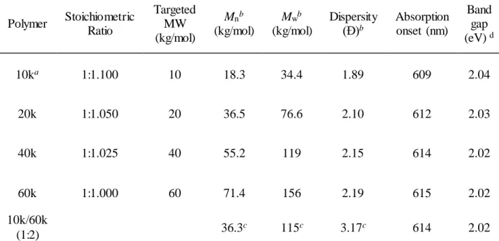
With carefully purified catalyst and monomers, we were able to vary the stoichiometric ratio of these two monomers to obtain PBnDT-FTAZ with the targeted molecular weight under the microwave condition. Table 3.1 summarizes the molecular weight data of our PBnDT-FTAZ polymers, together with the estimated band gap from the UV-Vis absorption onset. Please note that gel permeation chromatography (GPC), though generally accepted to estimate the molecular weight, only provides data relative to the standard (polystyrene in our case), and typically overestimates the molecular weight of conjugated polymers by a factor of 1.5 or higher relative to the true molecular weight.79,80 Thus we were pleased to observe a quite linear correlation of
32
Table 3.1 Controlling the molecular weight of PBnDT-FTAZ via tuning stoichiometric ratio
Polymer Stoichiometric Ratio
Targeted MW (kg/mol)
Mnb
(kg/mol)
Mwb
(kg/mol)
Dispersity (Đ)b
Absorption onset (nm)
Band gap (eV) d
10ka 1:1.100 10 18.3 34.4 1.89 609 2.04
20k 1:1.050 20 36.5 76.6 2.10 612 2.03
40k 1:1.025 40 55.2 119 2.15 614 2.02
60k 1:1.000 60 71.4 156 2.19 615 2.02
10k/60k
(1:2) 36.3
c 115c 3.17c 614 2.02
a “10k” is denoted for the polymer with the targeted molecular weight of 10 kg/mol, “20k” for the polymer with the targeted molecular weight of 20 kg/mol, etc.
b Determined by GPC in 1,2,4-trichlorobenzene at 150 °C c Calculated according to GPC values.
d Measured from film absorption spectra at λ
max.
10 20 30 40 50 60
10 20 30 40 50 60 70 80
Mn mea
sure
d by G
PC (kDa
)
Calculated Mn (kDa)
r=0.98
slope=1.30
33
3.3 Photovoltaic performance and electrochemical properties
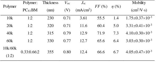
The photovoltaic characterization of these four polymers shows a clear impact on the performance by the molecular weight (Figure 3.2 and Table 3.2). For fair comparison, devices were fabricated according to an optimized condition we reported ear lier[3b] (see experimenal section for details). Indeed, the highest efficiency (over 7%) is the device based on the 40k polymer, with a Jsc of 12.9 mA/cm2, a Voc of 0.79 V, and a FF over 70%. In contrast, lower
molecular weight polymers (10k and 20k) based BHJ devices offer much lower efficiency values, primarily because of the reduced Jsc and FF (Table 3.2). Further increasing the molecular weight
beyond 40 kg/mol, for example, in the case of the 60k polymer, leads to a noticeably lower solubility in the processing solvent (trichlorobenzene). Nevertheless, the BHJ device based on the 60k polymer still shows an efficiency of 6.4%, a value slightly lower than that obtained from the device based on the 40k polymer (7.3%). To further understand the impact of mo lecular weight on the device performance, we mixed 10k and 60k polymers by 1:2 weight ratio to “recreate” the 40k polymer with a Mw very close to that of the as-synthesized 40k polymer (but Mn close to that of the as-synthesized 20k polymer). Interestingly, such a “recreated” 40k
34
IPCE of 70% for the polymer (near 600 nm) but a significant suppression to near 40% for the fullerene at 400 nm.
Table 3.2 Average photovoltaic performance and hole mobility of PBnDT-FTAZ: PC61BM
devices with different molecular weights
Polymer Polymer: PC61BM
Thickness (nm)
Voc
(V)
Jsc
(mA/cm2) FF (%) η (%)
Mobility (cm2/V·s)
10k 1:2 230 0.71 3.61 55.5 1.4 1.75±0.37×10⁻³
20k 1:2 320 0.71 11.6 60.4 5.0 3.31±0.41×10⁻³
40k 1:2 315 0.79 12.9 71.9 7.3 4.10±0.30×10⁻³
60k 1:2 330 0.77 12.7 65.6 6.4 3.03±0.30×10⁻³
10k/60k
(1:2) 0.33:0.66:2 355 0.80 12.4 66.6 6.7 4.05±0.47×10
-3
Figure 3.2 (a) Current density vs. voltage curves and (b) Incident photon to current efficiency (IPCE) curves of PBnDT-FTAZ: PC61BM devices with molecular weight ranging from 10
kg/mol to 60 kg/mol. All polymer: PC61BM blends were prepared in trichlorobenzene (TCB) as
the processing solvent.
0.0 0.2 0.4 0.6 0.8 1.0
-15 -10 -5 0 5 10 15 C u rr e n t D e n sit y ( m A /c m 2 ) Voltage (V) 10k 20k 40k 60K 10K/60K (a) (b)
400 500 600 700
0 10 20 30 40 50 60 70 80 10K 20K 40K 60K 10K/60K E Q E ( % ) Wavelength (nm)
0.0 0.2 0.4 0.6 0.8 1.0
-15 -10 -5 0 5 10 15 C ur re nt D en sit y ( m A /c m 2 ) Voltage (V) 10k 20k 40k 60K 10K/60K (a) (b)
400 500 600 700
35
So what cause(s) this interesting impact of molecular weight of PBnDT-FTAZ on its BHJ device performance? First, the difference in molecular weight has little impact on the absorption of PBnDT-FTAZ in solution and as thin films (Figure 3.3). When PBnDT-FTAZ is blended with PC61BM in the active layer, the blend based on the 10k polymer does show a lower absorbance
in the region (500 nm to 600 nm) where PBnDT-FTAZ absorbs the most (Figure 3.4). However, this minor difference in the absorbance cannot account for the significantly lower Jsc as obtained
from the 10k polymer based BHJ devices. Second, the measured energy levels for all studied polymers are very similar (Table 3.3), with similar band gaps as well. Therefore, a plausible explanation – the molecular weight influencing the device properties via changing the optical and electronic properties of these polymers – is essentially ruled out. Third, the charge carrier mobility (measured by Space Charge Limited Current method (SCLC) increases by a factor of two as the molecular weight increases from 10 kg/mol to 40 kg/mol (Table 3.2). However, this difference on the mobility can only partially account for the observed significant increase of the Jsc from the 10k polymer based BHJ devices to the 40k based devices, since the “low” hole
mobility of the 10k polymer based devices, 1.75 × 10⁻³ cm2/V·s, is sufficiently high to sustain a
high Jsc.81
400 500 600 700
0.0 0.2 0.4 0.6 0.8
1.0 10k 20k
40k 60k 10k/60k No rmal ize d Absor ptio n (a.u.) Wavelength (nm)
400 500 600 700 0.0 2.0x10⁴ 4.0x10⁴ 6.0x10⁴ 8.0x10⁴ 1.0x10⁵ Abso rptio n Co eff ici en t (cm -1 ) Wavelength (nm) 10k 20k 40k 60k 10k/60k