Features
▶ Specially developed for hydrostatic fan drives ▶ The A10VER variable motor is equipped with an
overcenter rotary group with a maximum displacement of +/-100% Vg max. This allows reversing operation without the need for costly additional components to reverse the air flow and to clean the cooler from contaminations which leads to fuel savings due to improved cooling performance.
▶ The energy efficiency of hydraulic fan drives is increased due to the elimination of external reversing valves. ▶ Stable bearing for long service life
▶ High maximum output speed
▶ Favorable power-to-weight ratio – compact dimensions ▶ Low noise level
Project planning and commissioning notes
Axial piston variable motor A10VER
Series 52
For hydrostatic fan drives in open circuit
Contents
Product description 2
Technical data 2
Project planning 3
1 Product description
The variable motor A10VER is available in a plug-in design. The A10VER is a variable motor with axial piston rotary group in swashplate design for hydrostatic fan drives in open circuits. For axial piston units with swashplate design, the pistons (7) are arranged axially to the drive shaft (1). The pistons place a load on the swashplate (cradle) (9) and transfer the torque dependent on pressure and swivel angle via the cylinder (6) to the drive shaft (1). The cylinder (6) and drive shaft (1) are interlocked. The control of the swashplate (cradle) (9) can change the specific torque and displacement.
In an open circuit, the hydraulic fluid flows from the reservoir to the hydraulic pump, where it is transported to the hydraulic motor. The hydraulic fluid flows from the hydraulic motor directly back to the reservoir. The output direction of rotation of the hydraulic motor is changed by overcentering the swashplate (9) to ‒100% Vg max, without changing the pressure side.
Axial piston unit layout
5 4 1 8 9 6 7 3 2 11 12 10
Fig. 1: Layout of the A10VER hydraulic motor
1 Drive shaft 2 Retaining plate 3 Stroking piston 4 Control plate (Distributor plate) 5 Port plate 6 Cylinder 7 Piston 8 Slipper pad 9 Swashplate (Cradle) 10 EZ control valve 11 Anti cavitation valve 12 Time-delay orifice
1.1 Functional description
A hydraulic motor converts hydrostatic energy into mechanical energy. Hydraulic fluid is supplied via the port plate (5) and the control plate (distributor plate) (4) to the cylinder bores. The pistons (7) in the cylinder bores execute a stroke. The pressure on the piston makes it slide downwards onto the swashplate and takes the cylinder (6) with it. The cylinder rotates with the drive shaft (1) which causes it to generate an output torque. The output torque increases with the pressure difference between the high- and low-pressure sides and increasing displacement. The output speed is proportional to the inward flow and inversely proportional to the displacement of the hydraulic motor.
The swivel angle of the swashplate (cradle) (9) is
switchable from +100% to ‒100% (EZ two-point control). Control of the swivel angle of the swashplate changes the piston stroke and therefore the displacement. Also the hydraulic motor's direction of rotation is changed by swiveling through the neutral position. The swivel angle is controlled electrically via the stroking piston (3). Increasing the swivel angle results in an increase in the displacement and specific torque; decreasing the swivel angle results in a corresponding decrease of these values. The output speed depends on the input flow and the displacement of the hydraulic motor or the electrical pressure control (ED) of the variable displacement pump.
2 Technical data
The permissible technical data for your axial piston unit can be found on the data sheet 91706. Additional information can be found in the product-specific instruction manual 91706-B.
The data sheet and the instruction manual, along with more information, can be found at:
3 Project planning
Reversing function:
Hydraulic system requirements
▶ In order to configure system pressure using the ED solenoid of the variable displacement pump, various wait and ramp times must be determined and programmed in the customer software required for reversing prior to commissioning.
If there is a cable break on the ED control valve of the axial piston unit and the reverse signal is controlled by the software, it must be programmed to not engage the reversing valve of the variable motor when a cable break is detected.
▶ Do not overcenter the hydraulic motor on cold start or when viscosity is high. There is a danger that the hydraulic motor gets stuck in the neutral position at Vg = 0 cm3. The minimum hydraulic fluid temperature on the high-pressure side at which commissioning is successful must be implemented in the software. Due to various factors, a slightly higher temperature should be programmed. Do not reverse the motor unless this minimum temperature is met.
▶ Pressure controllers are not safeguards against pressure overload. A pressure relief valve is to be fitted in the hydraulic system.
Recommended operating states when reversing
The hydraulic motor reversing function should only be used at a Δ pressure of at least 30 bar and maximum 45 bar between ports B and A. Bosch Rexroth recommends 35 bar. The reversing function is allowed to be initiated at a fan speed of less than 1000 rpm and a high pressure of less than 50 bar abs. (on port B).
▶ Use the ED control valve to increase control current and regulate the working pressure of the hydraulic pump so that a Δp pressure of 30 to 45 bar is generated. This pressure sets the fan speed to less than 1000 rpm. If this does not occur, please contact us.
Abruptly switching off the diesel engine without checking the fan speed can result in cavitation damage to the hydraulic motor.
To avoid cavitation damage or to extend service life, we recommend adding an anti cavitation valve to the hydraulic motor.
Definition of terms Reversing pressure
The Δ pressure between A and B at which the system switches from fan operation to reversing operation and then from reversing operation back to fan mode is between 30 and 45 bar (relative). The pressure in B must be less than 50 bar.
Reversing current
The current at which a pressure of 30 to 45 bar is set. Reversing speed
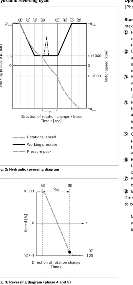
Hydraulic reversing cycle 0 0 1 2 3 4 5 6 7 8 pmax 35 +nmax < +1000 > -1000 –nmax W or king pr es sur e p [bar] Mo tor speed [r pm]
Direction of rotation change > 5 sec Time t [sec]
Rotational speed Working pressure Pressure peak
Fig. 2: Hydraulic reversing diagram
4 5 >5s 10097 n1 (+) n2 (–) 0 t Speed [%]
Direction of rotation change Time t
Fig. 3: Reversing diagram (phase 4 and 5)
Operating phases required for reversing operation (Phases see Fig. 2)
Starting state: Cooling operation at maximum speed and maximum pressure.
1 Reduction in system pressure by increasing the current controlled by the axial piston unit with ED control valve to reach a reversing pressure.
2 Current at the ED control valve is at reversing current and system pressure decreases. Hydraulic motor speed continues to decrease based on the fan wheel's moment of inertia.
3 Working pressure of the axial piston unit with ED control valve has reached the reversing pressure. Wait time until the hydraulic motor reaches a reversing speed (less than 1000 rpm) at a reversing pressure.
4 Reversing valve (EZ control valve) engages and the hydraulic motor begins reversing direction of rotation. A pressure peak can occur in the system while the motor is changing direction of rotation due to a change in motor quadrants and the fan wheel's moment of inertia. 5 Only after 97% of the "reversing speed" at reversing
pressure has been reached is there an increase in pressure on the axial piston unit via a reduction in voltage on the ED solenoid.
6 ED voltage is at minimum, working pressure continues to increase to maximum. Speed in reversing operation continues to increase further.
7 Working pressure is at maximum, hydraulic motor speed continues to increase.
8 Maximum speed in the reversing function is reached. Direction of rotation is changed from reversing operation to cooling operation in the same way.
More information on axial piston units with ED control valves can be found on data sheets 92703, 92735, 92650 and 92701.
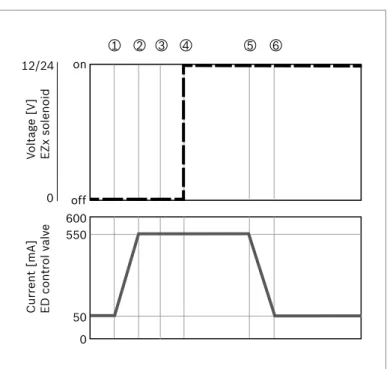
Electrical reversing cycle 1 2 3 4 5 6 off on 550 600 50 0 12/24 0 Volt age [V] EZx solenoid Cur rent [mA] ED contr ol v al ve
Fig. 4: Electrical reversing diagram, example for 24 V ED72 version
Example of wait and ramp times of a reversing cycle for ED72 with 24 V.
Starting state: Axial piston unit ED control valve at minimum current, EZx hydraulic motor control valve de-energized.
1 Axial piston unit ED control valve is energized from Imin (the configured current necessary to reach maximum required fan power/speed) to standby reversing current (in this example, approx. 550 mA). Ramp time is 3 seconds.
2 ED control valve current matches reversing current. Wait time of 1 second until reversing pressure is reached. 3 Working pressure of the axial piston unit with ED control
valve is the reversing pressure. Wait time until the hydraulic motor reaches reversing speed.
4 To initiate the reversal of the direction of rotation of the fan wheel, the EZ control valve of the hydraulic motor is energized with a subsequent wait time of 5 seconds. 5 ED control valve current decreases from 550 mA
(reversing current) to Imin, ramp time is 3 seconds. The programming for reversing direction of rotation from reversing operation to fan operation is the exact opposite.
Notice
The values (ramp and wait times) mentioned here are reference values for initial project planning and may have to be adjusted to meet specification.
The wait and ramp times, minimum and maximum solenoid current, and standby reversing current must be programmed before commissioning. Once the reversing cycle is adapted and set during commissioning, it can no longer be changed during operation.
• Effects of too short reversing times – High pressure peaks in the system
– High potential of cavitation in the hydraulic motor – High backflow to hydraulic motor from low pressure
line (filter)
– High acceleration forces on the fan wheel • Effects of too long reversing times
– There is a danger that the combination of insufficient orifice diameter and excessive hydraulic fluid viscosity will cause the hydraulic motor to remain in the neutral position Vg = 0 cm3.
Please contact us with any additional questions. [email protected]
3.1 Notices on project planning
It´s not allowed to use a check valve in the low pressure line, since cavitation can result from return flow on the low-pressure side, which may arise from overcentering and changing the hydraulic motor's direction of rotation. Filter insertion
To avoid cavitation, residual hydraulic fluid must be present in the low-pressure side when overcentering the hydraulic motor to ensure that the motor is able to momentarily feed. The system owner must ensure that the hydraulic fluid volume between the hydraulic motor and the filter is large enough that any solid particles are not sucked from the filter through the low-pressure port when reversing the motor's direction of rotation.
An orifice allows the hydraulic motor to switch from cooling operation speed at reversing pressure to reversing operation speed at reversing pressure in > 5 seconds. Direction of rotation is changed from reversing operation to cooling operation in the same way.
▶ This time can be adjusted by adding another orifice and/or increasing or decreasing the pressure difference between ports B and A. If it does not take more than 5 seconds to change the direction of rotation, please contact us. Other orifice diameters available upon request.
▶ For determining the appropriate time for changing the hydraulic motor's direction of rotation, see also the diagram
Fig. 3 "Reversing diagram (phase 4 and 5)" on page 4.
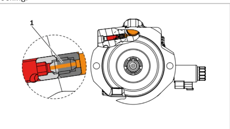
▶ Various factors can cause the orifice to become clogged during the swivel times, prolonging or even preventing swiveling when reversing. If this occurs, try to switch to reversing operation again. The orifice should unclog itself and function normally.
Also observe chapter 3 "Project planning" on page 3. The orifice (1) is secured to the motor housing with a screw locking.
1
4 Safety instructions
Unexpected fan speed control behavior!
Risk of injury from fan wheel activating on system start or after repair.
▶ When unpowered, the motor can reach maximum speed depending on the position of the drive unit (unpowered motor is swiveled out fully with pressure build-up). Attention: Unplugging the electrical control (ED) of the drive unit and/or electrical control (EZ) of the hydraulic motor does not result in a safe standstill, but to rotation of the fan wheel at maximum speed.
▶ Check whether or not your machine requires additional safety measures for your application.
Suction effect from running fan wheel.
Risk of injury or death. A running fan wheel produces a suction effect that can pose a danger of entanglement. ▶ Standing in the danger zone of the rotating fan wheel
is prohibited.
Before entering the danger zone ensure the fan wheel has stopped, e.g., by disconnecting the drive source.
Fan wheel at a standstill while machine is running. Risk of injury or death from sudden fan wheel movement. ▶ Never reach into the machine while it is running, e.g.,
to get the fan wheel to move.
▶ Use reversing to attempt to get the fan wheel to move again.
See also chapter 3.1 "Notices on project planning" on page 6 and instructions on what to do.
▶ Check whether or not your machine requires additional safety measures for your application.
▶ We recommend programming the reversing function so it can only be started when the viscosity/operating temperature in the hydraulic fluid circuit is high enough (testing during commissioning).
Bursting of hydraulic lines and/or damage to components (e.g., shaft, fan blades).
Risk of injury or death, or property damage.
▶ Never unplug the solenoids while reversing operation is active.
▶ Never disconnect the power supply while reversing operation is active.
Please contact us with any additional questions. [email protected]
Other product-specific information can be found in the instruction manual 91706-01-B
Bosch Rexroth AG An den Kelterwiesen 14
© Bosch Rexroth AG 2019. All rights reserved, also regarding any disposal, exploitation, reproduction, editing, distribution, as well as in the event