00813-0200-4420, Rev GB
Gateway connects wireless self-organizing networks with any host system
Easy configuration and management of self-organizing networks
Easy integration into control systems and data applications through serial and Ethernet LAN connections
Seamless integration into AMS
®Device Manager and DeltaV
™automation system
Greater than 99% reliability with industry proven security
Smart Wireless capabilities extends the full benefit of PlantWeb
®architecture to previously inaccessible
locations
Emerson Smart Wireless Gateway
Gain real-time process information with greater than 99% wireless data
reliability
The Smart Wireless Gateway automatically manages wireless communications in constantly changing environments. Native integration with DeltaV and Ovation automation systems provides simple and fast commissioning for wireless field
networks.
Connect to data historians, legacy host systems, and other via a LAN applications through Ethernet, Modbus®, Serial, OPC, EtherNet/IP™, and HART® outputs.
Guarantee system availability with redundant
Smart Wireless Gateways
Never lose the wireless network with hot standby capability and automatic fault detection.
Smart Wireless Gateways function as a single system, eliminating the need for duplicate host integration.
One-click configuration and plug-and-play architecture
Complete wireless network configuration tools
provided with each Gateway
The integrated web interface allows easy configuration of the wireless network and data integration without the need to install additional software.
Complimentary AMS Wireless Configurator software provides Emerson Device Dashboards to configure devices and view diagnostic data.
Drag and drop device provisioning enables a secure method to add new wireless devices to the wireless field network.
Contents
Emerson’s Smart Wireless Solution . . . 3
Ordering Information . . . 4
Accessories and spare parts . . . 5
Specifications . . . 6
Product Certifications . . . 8
Emerson’s Smart Wireless Solution
IEC 62591 (
Wireless
HART
®
)... The industry
standard
Self-organizing, adaptive mesh routing
No wireless expertise required, network automatically finds the best communication paths
The self-organizing, self-healing network manages multiple communication paths for any given device. If an obstruction is introduced into the network, data will continue to flow because the device already has other established paths. The network will then lay in more communication paths as needed for that device.
Reliable wireless architecture
Standard IEEE 802.15.4 radios
2.4 GHz ISM band sliced into 15 radio-channels
Time Synchronized Channel Hopping to avoid interference from other radios, Wi-Fi, and EMC sources and increase reliability
Direct sequence spread spectrum (DSSS) technology delivers high reliability in challenging radio environment
Emerson’s Smart Wireless
Seamless integration via LAN to all existing host
systems
Native integration into DeltaV and Ovation is transparent and seamless
Gateways interface with existing host systems via a LAN, using industry standard protocols including OPC, Modbus TCP/IP, Modbus RTU, and EtherNet/IP
Layered security keeps your network safe
Ensures data transmissions are received only by the Smart Wireless Gateway
Network devices implement industry standard Encryption, Authentication, Verification, Anti-Jamming, and Key Management Third party security verification including Achilles and FIPS197- User
based login and enforced password strength. Password strength
monitoring, user based log in, password reset requirements, automatic lockout, password expiration requirements. Based on guidelines from ISA99.03.03 standard approved level two.
SmartPower
™solutions
Optimized Emerson instrumentation, both hardware and software, to extend power module life SmartPower technologies enable predictable power life
Ordering Information
Specification and selection of product materials, options, or components must be made by the purchaser of the equipment. See
page 6 for more information on Material Selection.
Table 1. Smart Wireless Gateway Ordering Information
★ The Standard offering represents the most common options. The starred options (★) should be selected for best delivery.
__The Expanded offering is subject to additional delivery lead time.
Model Product description
1420 Smart Wireless Gateway
Power input
A 24 VDC nominal (10.5-30 VDC) ★
Ethernet communications - physical connection
1(1)(2) Ethernet ★
2(3)(4) Dual Ethernet ★
Wireless update rate, operating frequency, and protocol
A3 User configurable update rate, 2.4 GHz DSSS, WirelessHART ★
Serial communication
N None ★
A(5) Modbus RTU via RS485 ★
Ethernet communication - data protocols
2 Webserver, Modbus TCP/IP, AMS ready, HART-IP™ ★
4 Webserver, Modbus TCP/IP, AMS ready, HART-IP, OPC ★
5(6) DeltaV ready ★
6(6) Ovation ready ★
8 Webserver, EtherNet/IP, AMS ready, HART-IP ★
9 Webserver, EtherNet/IP, Modbus TCP/IP, AMS ready, HART-IP ★
Options
(include with selected model number)Product certifications
N5 U.S.A. Division 2 ★
N6 CSA Division 2, Non-incendive ★
N1(7) ATEX Type n ★
ND(7) ATEX Dust ★
N7(7) IECEx Type n ★
NF(7) IECEx Dust ★
KD(7) FM & CSA Division 2, Non-incendive and ATEX Type n ★
N3(7) China Type n ★
N4(7) TIIS Type n ★
Accessories and spare parts
Redundancy options(8)(9)(10) RD Gateway redundancy ★ Adapters J1 CM 20 conduit adapters ★ J2 PG 13.5 conduit adapters ★ J3 3/4 NPT conduit adapters ★ Antenna options(11)WL2 Remote antenna kit, 50-ft. (15.2 m) cable, lightning arrestor ★
WL3 Remote antenna kit, 20-ft. (6.1 m) and 30-ft. (9.1 m) cables, lightning arrestor ★
WL4 Remote antenna kit, 10-ft. (3.0 m) and 40-ft. (12.2 m) cables, lightning arrestor ★
WN2(12) High-gain, remote antenna kit, 25-ft. (7.6m) cable, lightning arrestor
Typical model number: 1420 A 2 A3 A 2 N5
1. Single active 10/100 baseT Ethernet port with RJ45 connector. 2. Additional ports disabled.
3. Dual active 10/100 baseT Ethernet ports with RJ45 connectors.
4. Multiple active ports have separate IP addresses, firewall isolation, and no packet forwarding. 5. Convertible to RS232 via adaptor, not included with Gateway.
6. Includes Webserver, Modbus TCP, AMS Ready, HART-IP, and OPC.
7. Options may or may not come with POE. See terminal block configuration for determination if the device is compatible with POE or see the 1420 Manual. 8. Requires the selection of Dual Ethernet option code 2.
9. Not available with DeltaV Ready option code 5. 10. Not available with EtherNet/IP option codes 8 and 9
11. The WL2, WL3, WL4, and WN2 options require minor assembly. 12. Not available in all countries.
Table 1. Smart Wireless Gateway Ordering Information
★ The Standard offering represents the most common options. The starred options (★) should be selected for best delivery.
__The Expanded offering is subject to additional delivery lead time.
Table 2. Spare Parts
Item description Part number
Spare kit, WL2 replacement(1), remote antenna, 50-ft. (15.2 m) cable, and lightning arrestor 01420-1615-0302 Spare kit, WL3 replacement(1), remote antenna, 20/30-ft. (6.1/9.1 m) cables, and lightning arrestor 01420-1615-0303
Spare kit, WL4 replacement(1), remote antenna, 10/40-ft. (3.0/12.2 m) cables, and lightning arrestor 01420-1615-0304
Spare kit, WN2 replacement(1), high gain, remote antenna, 25-ft. (7.6 m) cable, and lightning arrestor(2) 01420-1615-0402
1. Can not upgrade from integral to remote antenna. 2. Not available in all countries.
Specifications
Functional specifications
Input power
10.5 - 30 VDC
Current draw
For non-POE enabled Gateways, the operation current draw is based on 3.6 Watts average power consumption.
Momentary startup Current Draw up to twice Operating Current Draw.
Power and Ethernet
PSE mode50v - 57 vDC Output 9per IEEE 802.3at-2009) 25.5 W maximum
Radio frequency power output from antenna
Maximum of 10 mW (10 dBm) EIRP
Maximum of 40 mW (16 dBm) EIRP for WN2 High Gain option
Environmental
Operating Temperature Range
-40 to 158 °F (-40 to 70 °C)
Operating Humidity Range
10-90% relative humidity
EMC performance
Complies with EN61326-1:2006.
Antenna options
Integrated Omni-directional Antenna
Optional remote mount Omni-directional Antenna
Physical specifications
Material selection
Emerson provides a variety of Rosemount product with various product options and configurations including materials of construction that can be expected to perform well in a wide range of applications. The Rosemount product information presented is intended as a guide for the purchaser to make an appropriate selection for the application. It is the purchaser’s sole responsibility to make a careful analysis of all process parameters (such as all chemical components, temperature, pressure, flow rate, abrasives, contaminants, etc.), when specifying product, materials, options and components for the particular application. Emerson Process Management is not in a position to evaluate or guarantee the compatibility of the process fluid or other process parameters with the product, options, configuration or materials of construction selected.
Weight
10 lb (4.54 kg)
Material of construction
HousingLow-copper aluminum, NEMA 4X
Paint Polyurethane Cover gasket Silicone Rubber Antenna Integrated Antenna: PBT/PC Remote Antenna: Fiber Glass
Certifications
Class I Division 2 (U.S.) Equivalent Worldwide 24 30 125 250 Curre nt (mA) 12 10.5 Operating Region Voltage (VDC)
Communication specifications
Isolated RS485
2-wire communication link for Modbus RTU multi drop connections
Baud rate: 57600, 38400, 19200, or 9600 Protocol: Modbus RTU
Wiring: Single twisted shielded pair, 18 AWG. Wiring distance up to 4,000 ft. (1,524 m)
Ethernet
10/100base-TX Ethernet communication port
Protocols: EtherNet/IP Modbus TCP, OPC, HART-IP, HTTPS (for Web Interface)
Wiring: Cat5E shielded cable. Wiring distance 328 ft. (100 m).
Modbus
Supports Modbus RTU and Modbus TCP with 32-bit floating point values, integers, and scaled integers.
Modbus Registers are user-specified.
OPC
OPC server supports OPC DA v2, v3
EtherNet/IP
Supports EtherNet/IP protocol with 32 bit Floating Point values and Integers.
EtherNet/IP Assembly Input-Output instances are user configurable.
EtherNet/IP specifications are managed and distributed by ODVA.
Self-organizing network specifications
Protocol
IEC 62591 (WirelessHART), 2.4 - 2.5 GHz DSSS.
Maximum network size
100 wireless devices @ 8 sec or higher. 50 wireless devices @ 4 sec.
25 wireless devices @ 2 sec. 12 wireless devices @ 1 sec.
Supported device update rates
1, 2, 4, 8, 16, 32 seconds or 1 - 60 minutes
Network size/latency
100 Devices: less than 10 sec. 50 Devices: less than 5 sec.
Data reliability
>99%
PoE
Supports IEEE 802.11 PoE as a PD or a PSE on either Port; jumper selectable. PSE ratings: IEEE 802.11af for 12VDC input and IEEE 802.11at for 24VDC input
System security specifications
Ethernet
Secure Sockets Layer (SSL)- enabled (default) TCP/IP communications
Smart Wireless Gateway Access
Role-based Access Control (RBAC) including Administrator, Maintenance, Operator, and Executive. Administrator has complete control of the gateway and connections to host systems and the self-organizing network.
Self-organizing network
AES-128 Encrypted WirelessHART, including individual session keys. Drag and drop device provisioning, including unique join keys and white listing.
Internal firewall
User Configurable TCP ports for communications protocols, including Enable/Disable and user specified port numbers. Inspects both incoming and outgoing packets.
Third party certification
Wurldtech: Achilles Level 1 certified for network resiliency. National Institute of Standards and Technology (NIST): Advanced Encryption Standard (AES) Algorithm conforming to Federal Information Processing Standard Publication 197 (FIPS-197)
Product Certifications
Rev 1.1European Directive Information
A copy of the EC Declaration of Conformity can be found at the end of the Quick Start Guide. The most recent revision of the EC Declaration of Conformity can be found at
www.rosemount.com.
Telecommunication Compliance
All wireless devices require certification to ensure that they adhere to regulations regarding the use of the RF spectrum. Nearly every country requires this type of product certification. Emerson is working with governmental agencies around the world to supply fully compliant products and remove the risk of violating country directives or laws governing wireless device usage.
FCC and IC
This device complies with Part 15 of the FCC Rules. Operation is subject to the following conditions: This device may not cause harmful interference. This device must accept any interference received, including interference that may cause undesired operation. This device must be installed to ensure a minimum antenna separation distance of 20 cm from all persons.
Ordinary Location Certification
As standard, the transmitter has been examined and tested to determine that the design meets the basic electrical,
mechanical, and fire protection requirements by a nationally recognized test laboratory (NRTL) as accredited by the Federal Occupational Safety and Health Administration (OSHA).
Installing Equipment in North America
The US National Electrical Code (NEC) and the Canadian Electrical Code (CEC) permit the use of Division marked equipment in Zones and Zone marked equipment in Divisions. The markings must be suitable for the area classification, gas, and temperature class. This information is clearly defined in the respective codes.
USA
N5 U.S.A. Division 2
Certificate: CSA 70010780
Standards: FM Class 3600 - 2011, FM Class 3611 - 2004, FM Class 3616 - 2011, UL 50 - 11th Ed, ANSI/ISA 61010-1 - 2012
Markings: NI CL 1, DIV 2, GP A, B, C, D T4;
Suitable for use in CL II, III, DIV 2, GP F, G T4; T4(-40 °C ≤ Ta ≤ +60 °C);
Nonincendive outputs to remote antenna when connected per Rosemount drawing 01420-1011; Type 4X
Special Condition for Safe Use:
1. Explosion Hazard. Do not disconnect equipment when a flammable or combustible atmosphere is present.
Canada
N6 Canada Division 2 Certificate: CSA 70010780
Standards: CAN/CSA C22.2 No. 0-M91 (R2001), CAN/CSA Std C22.2 No. 94-M91 (R2001), CSA Std C22.2 No. 142-M1987,
CSA Std C22.2 No. 213-M1987, CSA C22.2 No. 61010-1 – 2012
Markings: Suitable for Class 1, Division 2, Groups A, B, C, and D, T4; when connected per Rosemount drawing 01420-1011; Type 4X
Special Condition for Safe Use:
1. Explosion Hazard. Do not disconnect equipment when a flammable or combustible atmosphere is present.
Europe
N1 ATEX Type n Certificate: Baseefa07ATEX0056X Standards: EN 60079-0: 2012, EN 60079-15: 2010 Markings: II 3 G Ex nA IIC T4 Gc, T4(-40 °C ≤ Ta ≤ +65 °C), VMAX = 28 VdcSpecial Conditions for Safe Use (X):
1. The equipment is not capable of withstanding the 500V insulation test required by clause 6.5.1 of EN
60079-15:2010. This must be taken into account when installing the3 equipment.
2. The surface resistivity of the antenna is greater than 1GΩ. To avoid electrostatic charge build-up, it must not be rubbed with a dry cloth or cleaned with solvents.
ND ATEX Dust
Certificate: Baseefa07ATEX0057X
Standards: EN 60079-0: 2012, EN 60079-31: 2009 Markings: II 3 D Ex tc IIIC T135 °C Dc,
(-40 °C ≤ Ta ≤ +65 °C)
Special Condition for Safe Use (X):
1. The surface resistivity of the antenna is greater than 1GΩ. To avoid electrostatic charge build-up, it must not be rubbed with a dry cloth or cleaned with solvents.
International
N7 IECEx Type nCertificate: IECEx BAS 07.0012X
Standards: IEC 60079-0: 2011, IEC 60079-15: 2010 Markings: Ex nA IIC T4 Gc, T4(-40 °C ≤ Ta ≤ +65 °C),
VMAX = 28 Vdc
Special Conditions for Safe Use (X):
1. The apparatus is not capable of withstanding the 500 V electrical strength test as defined in Clause 6.5.1 of IEC 60079-15:2012. This must be taken into account during installation.
2. The surface resistivity of the antenna is greater than 1GΩ. To avoid electrostatic charge build-up, it must not be rubbed with a dry cloth or cleaned with solvents.
NF IECEx Dust
Certificate: IECEx BAS 07.0013
Standards: IEC 60079-0: 2011, IEC 60079-31: 2008 Markings: Ex tc IIIC T135 °C Dc, (-40 °C ≤ Ta ≤ +65 °C)
Special Condition for Safe Use (X):
1. The surface resistivity of the antenna is greater than 1GΩ. To avoid electrostatic charge build-up, it must not be rubbed with a dry cloth or cleaned with solvents.
Brazil
N2 INMETRO Type n
Certificate: CEPEL 09.1844X
Standards: ABNT NBR IEC 60079-0:2008, IEC 60079-15:2010,
ABNT NBR IEC 60529:2009; Markings: Ex nA nL IIC T4 Gc
Special Condition for Safe Use (X):
1. See certificate for special conditions.
China
N3 China Type n
Certificate: CNEx13.1929X
Standards: GB3836.1 – 2010, GB3836.8 - 2003 Markings: Ex nA nL IIC T4 Gc
Special Condition for Safe Use (X):
1. See certificate for special conditions.
Japan
N4 TIIS Type nCertificate: T64855 Markings: Ex nA nL IIC T4
EAC – Belarus, Kazakhstan, Russia
NM Technical Regulation Customs Union (EAC) Type nCertificate: RU C-US.ГБ05.B.00578 Markings: 2Ex nA IIC T4 X;
T4(-40 °C ≤ Ta≤ +65 °C) IP66;
Combinations
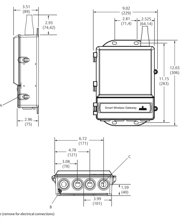
Dimensional Drawings
Figure 1. Smart Wireless GatewayA. Lower cover (remove for electrical connections) B. Ground lug
C. 1/2-in. NPT conduit connection (4 places)
Dimensions are in inches (millimeters).
9.02 (229) 2.81 (71,4) 2.525 (64,14) 11.15 (283) 12.03 (306) 2.93 (74,42) A 3.51 (89) 2.96 (75) 6.72 (171) 4.78 (121) 3.08 (78) 1.59 (40) 3.99 (101) B C
Figure 2. Remote Antenna Kit
The Remote Antenna kit includes sealant tape for remote antenna connection, as well as mounting brackets for the antenna, Lightning Arrestor, and the Smart Wireless Gateway.
Lightning protection is included on all the options.
Note
The cables lengths on the remote antenna options WL3 and WL4 are interchangeable for installation convenience. A. Antenna B. 20-ft. (6,1 m) cable C. 10-ft. (3,0 m) cable D. Lightning arrestor E. Interchangeable cables F. 50-ft. (15,2 m) cable G. 30-ft. (9,1 m) cable H. 40-ft. (12,2 m) cable I. 25-ft. (7,6 m) cable
WL2
WL2
WL3
WL3
WL4
WL4
WN2
WN2
A
A
A
A
B
C
D
D
D
D
E
E
F
G
H
I
Global Headquarters
Emerson Process Management 6021 Innovation Blvd.
Shakopee, MN 55379, USA
+1 800 999 9307 or +1 952 906 8888 +1 952 949 7001
North America Regional Office
Emerson Process Management 8200 Market Blvd.
Chanhassen, MN 55317, USA
+1 800 999 9307 or +1 952 906 8888
+1 952 949 7001 [email protected]
Latin America Regional Office
Emerson Process Management 1300 Concord Terrace, Suite 400 Sunrise, Florida, 33323, USA
+1 954 846 5030 +1 954 846 5121
Europe Regional Office
Emerson Process Management Europe GmbH Neuhofstrasse 19a P.O. Box 1046
CH 6340 Baar Switzerland
+41 (0) 41 768 6111 +41 (0) 41 768 6300
Asia Pacific Regional Office
Emerson Process Management Asia Pacific Pte Ltd 1 Pandan Crescent
Singapore 128461 +65 6777 8211 +65 6777 0947
Middle East and Africa Regional Office
Emerson Process Management Emerson FZE P.O. Box 17033, Jebel Ali Free Zone - South 2 Dubai, United Arab Emirates
+971 4 8118100 +971 4 8865465
Standard Terms and Conditions of Sale can be found at: www.rosemount.com\terms_of_sale.
The Emerson logo is a trademark and service mark of Emerson Electric Co. AMS is a registered trademark of Emerson Electric Co.
Rosemount and Rosemount logotype are registered trademarks of Rosemount Inc. SmartPower is a trademark of Rosemount Inc.
PlantWeb and DeltaV are registered trademarks of one of the Emerson Process Management group of companies.
HART and WirelessHART are registered trademarks of FieldComm Group. HART-IP is a trademark of the FieldComm Group.
EtherNet/IP is a trademark of ControlNet International under license by ODVA. Modbus is a registered trademark of Modicon, Inc.
All other marks are the property of their respective owners. © 2015 Rosemount Inc. All rights reserved.