Special Installation Requirements 3
Requirements for UL-Listed Installations 3 Canada Listings 3
California State Fire Marshall Listing 3
Introduction 4
System Components 4
Planning Sensor Types & Locations 6 Planning Control Locations 9
Planning Lamp, Appliance, Wallswitch & Uni-versal/Garage Module Control 9
Planning System Access Codes 10 Planning System Options 11
Wiring the Control Panel 15
Connecting Hardwire Interior Sirens 15 Connecting a Hardwire Exterior Siren 16 Connecting Hardwire Sensors 16
Connecting the Universal/Garage Door Module 16
Connecting the Power Transformer 16 Connecting the Backup Battery 17
Connecting the Phone Line to the Control Pan-el 17
Programming Overview 18
Programming Sensors 19
Programming House Code & Unit Numbers 19 Programming Light and Appliance Controls 20 Programming Options 21
Programming System Access Codes 22
Installing the System 22
Control Panel 22
Door/Window Sensor 24 Indoor Motion Sensor 25
Outdoor Motion Sensor 29 Smoke Sensor 29
KeyChain Touchpad 29
Remote Handheld Touchpad 30
Door/Window, Indoor/Outdoor Motion Sensor, KeyChain Touchpad, and Remote Handheld Touchpad FCC NOTICE 31
Testing the System 31
Testing Sensors 31
If a Sensor Fails the Sensor Test 32 Testing Phone Communication 33
Testing Central Station Communication 33 Testing X-10 Lamp Modules 33
Troubleshooting Guide 34 Notices 36
Duplicate Planning Sheets 38 List of Tables
Sensor/Device Location Planning 7 & 38 Recommended Sensor Types 7 & 38 Sensor Type Characteristics 8 & 39 Home Control Planning 10 & 40 System Access Codes 10
Programmable Options 14 & 40 Option 12: Phone Mod 1 12 Option 13: Phone Mod 2 12 Option 27: Ring/Hang/Ring 13 Option 31: Day of Week 14 Device Program Buttons 19
List of Figures
Typical Security System Components 4 Exterior Siren Panel Connections 16
Wire Hardwire Sensors Normally Closed 16 Power Transformer Panel Connections 16
Simon
™
Security System
Installation Instructions Document No. 466-1303 Revision B, June 3, 1997
Control Panel Backup Battery 17 RJ-31X Wiring Diagram 17
Control Panel Programming Decal 18 Light, Clock, Access Code, Sensor or Phone Test Decal 18 Sensor & Magnet Positions 24
Aligning the Door/Window Sensor & Magnet 24
Mounting Hole Locations (Bottom View) 24 Overhead (Bird’s Eye View) Detection Path 26 Top & Side Views Using PIR Lens 26 Side Views Mounting at Various Heights 27 Wall Mount Options 27
PIR Mounting Plate Knockouts 27 Sensitivity Pins Locations 28
PIR Components, Battery Locations, & Tamper Switch 29
Special Installation
Require-ments
This security system can be used as a fire warning system, an intrusion alarm system, an emergency no-tification system, or any combination of the three. Some installations may require certain configurations dictated by city codes, state codes, or insurance re-quirements. The following information indicates the components of various listings.
Requirements for UL-Listed
Installa-tions
This section describes the minimum system configu-rations for UL-listed, Grade A (supervised) systems.
Basic System
All UL-listed systems require the following basic components. The basic system does not require sen-sors and can use the Remote Handheld Touchpad as a controlling device.
• Control Panel (60-693-95R)
• Class II Line Carrier Power Transformer
(22-091)
• 9-Volt, 1.2 Ah Lithium Backup Battery (34-037)
• Hardwire Siren (13-046) or Slimline Siren
(60-483-01) or “Mouse” Siren (13-373)
Residential Burglary Alarm System Unit (UL 1023)
Basic system above, plus:
• Door/Window Sensor (60-670-95R) suitable for
installation on non-ferrous surfaces only
Residential Fire Alarm System Unit (UL 985)
Basic system above, plus:
• System Sensor Smoke Sensor (60-506-95)
Canada Listings (pending)
Residential Burglary Alarm System Unit (ULC-S309)
Basic system as described for UL-listed installations, plus:
• Door/Window Sensor (60-670-95R)
Note: The KeyChain Touchpad #60-659 is UL Listed as a miscellaneous signalling device and is for supplementary use only.
CSA Certified Accessories
Residential Fire Warning System Control Unit (ULC-S545-M89)
Basic system as described for UL-listed installations, plus:
• Wireless Smoke Sensor (60-506-95)
• SUPSYNC (Supervisory Synchronization) set to
2 (hours)
California State Fire Marshall Listing
Introduction
This ITI Security System is easy to install if you plan ahead and do everything in the following order. 1. Plan where to locate the hardwire sirens, sensors
and Control Panel. Use the tear out planning sheets at back of this manual.
2. Wire the Class II transformer, hardwire sirens, and phone.
3. Decide how the sensors, lights, and system options will operate.
4. Program the sensors, lights and appliances, and system options.
5. Install sensors and Lighting Modules. 6. Test system.
Note: Program the sensors before installing them because the Control Panel and sensors must be in the same place for programming. After you’ve programmed each sensor, you can install them where you planned.
System Components
The system can monitor up to 17 sensors using any combination of the following sensors:
• Door/Window Sensor (60-670-95R)
• KeyChain Touchpad (60-659-95R)
• Remote Handheld Touchpad (60-671-95R)
• Indoor Motion Sensor (60-639-95R)
• Outdoor Motion Sensor (60-639-95R-OD)
• ITI 319.5 Sensors (including Smoke Sensors)
Note: CO Detectors are not currently compatible with this security system.
Note: You may use any of these modules:
• X-10 Lamp Modules (13-403)
• X-10 Appliance Modules (13-402)
• X-10 Powerhorn/Remote Siren Modules
(13-398)
• X-10 Universal/Garage Door Modules (13-399)
• X-10 Wall Switch Modules (13-397)
Note: Use of the above X-10 modules has not been inves-tigated by UL.
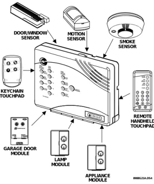
Figure 1. shows the Control Panel, control touchpads, and some compatible sensors and modules.
Figure 1. Typical Security System Components
Security System
The security system has three types of components: the Control Panel, devices that report to the Control Panel, and devices that respond to the Control Panel.
Control Panel
The Control Panel is the main processing unit for all security functions. It receives signals from and re-sponds to wireless sensors and wireless touchpads throughout the premises. The buttons operate the se-curity system. When using the Control Panel with the cover open, the buttons program the security system.
Door/Window Sensor
For intrusion protection, install Door/Window sen-sors on all ground-floor doors and windows. At a min-imum, install them in the following locations:
• All easily accessible exterior doors and windows.
• Interior doors leading into the garage.
• Doors to areas containing valuables such as
cabi-nets and closets.
KeyChain Touchpad
The KeyChain Touchpad enables you to turn the sys-tem on and off before entering the home or to turn on
X-10 POWERHOUSE 13 5 9 13 7 11 15 AC E I M G K O
UNIT CODE HOUSE CODE CONTINUOUS MOMENTARY
SOUNDER ONLY SOUNDER & RELAY
RELAY ONLY ON OFF DOOR/WINDOW SENSOR LAMP MODULE APPLIANCE MODULE GARAGE DOOR MODULE REMOTE HANDHELD TOUCHPAD MOTION SENSOR KEYCHAIN TOUCHPAD SMOKE SENSOR 8988G21A.DS4 13 5 9 13 7 11 15 AC E I M G K O 1 3 5 9 13 7 11 15 A C E I M G K O 7 4 1 8 9 5 2 6 3 Off s P EMERGENCY On d & s re sHolB tohK ye DISARM SYSTEM STATUS Doors & Windows ARM ARM SensorsMotion
-the siren and to call -the central monitoring station if there is an emergency. If you have Lamp Modules, you can use the KeyChain Touchpad to turn all lights on and off.
Remote Handheld Touchpad
The Remote Handheld Touchpad enables you to turn the system on and off while in the home, turn lights controlled by the system on and off (all or individual lights), or turn on a system siren and call the central monitoring station if there is a non-medical emergen-cy. The Remote Handheld Touchpad will report an alarm type specific to its sensor type (see Table 3 for sensor and siren types).
Indoor Motion Sensor
Indoor Motion Sensors are ideal whenever it is not practical to install Door/Window sensors on every opening. Identify areas where an intruder is likely to walk. Large areas in an open floor plan, downstairs family rooms, and hallways are candidates for Indoor Motion Sensors. Indoor Motion Sensors are not suit-able for rooms where pets can enter. Indoor motion sensors can also be used to sound chimes, but cannot be used for intrusion protection and as a chime sensor simultaneously.
Outdoor Motion Sensor
Use Outdoor Motion Sensors to identify motion in a protected outdoor area. Detected motion in this pro-tected area can sound chimes or turn on outside lights. Do not use Outdoor Motion Sensors for intrusion pro-tection.
Smoke Sensor
Smoke Sensors can provide fire alert protection by causing the alarm to sound throughout the house. You can add sensors near sleeping areas and other floors of the house. Avoid attics, kitchens, above fireplaces, dusty locations, and areas with temperature extremes. See the instructions packaged with the Smoke Sensor for complete placement information.
Refer to the diagram on the next page for specific placement of Smoke Sensors.
ITI ToolBox
The ITI ToolBox is a Windows®-based program that saves you time by simplifying Control Panel pro-gramming. Using only a PC, a modem, and a standard telephone line, ToolBox makes creating new custom-er accounts and updating the panel settings of existing customers simple and quick. See the ITI ToolBox manual and ToolBox’s on-line help for instructions to use ToolBox for programming this Control Panel.
ITI CS-4000 Receiver
The CS-4000 Receiver is used to monitor this security system.
Central Station Code - Central Station Locking
The central station code defaults to 12345. The secu-rity code can be changed from the central station us-ing the CSLOCK command. It can also be changed using the ITI ToolBox. The security code prevents any central station which does not have the proper se-curity code from establishing communications with the Control Panel.
ITI HomeLink Transceiver (IHT)
The ITI HomeLink Transceiver is a radio transmitter/ receiver designed to receive signals from the Prince Universal Transmitter (HomeLink®), then retransmit the signals to a security system panel, allowing the HomeLink® to control the arming, disarming, and light functions of the security system. The IHT also enables the user to control the garage door opener from the HomeLink®
Emergency Planning Floor Plan
Use the following guidelines when drawing an emer-gency planning floor plan for the homeowner:
• Show all building levels.
• Show exits from each room (2 exits per room are
recommended).
• Show the locations of all security system
compo-nents.
• Show the locations of any fire extinguishers.
Planning Sensor Types & Locations
The first step to an easy and successful installation is to decide what areas or items to protect which lights or appliances to operate, and the best location for the Control Panel, sensors or sirens. Use the previous
in-formation and Table 1, Device Location Planning, to note your requirements.
Use Table 2 and Table 3 to determine the appropriate Sensor Type for the sensors you will be adding. You’ll need to understand the application for each sensor. For example, KeyChain Touchpads are typi-cally programmed as sensor type 01 (Portable panic), used to send an intrusion alarm to a central monitoring station. This sensor type is instant intrusion, it does not require restoral or supervisory communication with the Control Panel and it is active in all 4 arming levels (disarm, arm doors & windows, arm motion sensors, and arm doors/windows and motions sen-sors). Living Room Dining Room Basement x H Hall Bedroom Bedroom Living Room Recreation Room Basement Hall Bedroom Bedroom Living Room Dining Room Hall Bedroom Bedroom Bedroom Kitchen
A smoke detector should be l ocated on each l evel .
Smoke detectors should be l ocated be twe e n th e sl eepi ng ar ea a n d th e r est of the family living unit.
NOTE: Do not in stall smoke detectors where normal ambient temper atures are above 100°F or below 40°F. Also, do not locate detectors in front of AC/ Heat registers or other lo cations where normal air circulatio n will keep smoke fr om entering the detector.
NOTE: Additional in format ion on household fire warning is availa ble at nominal cost from: The National Fire Protection Association, Batterymarch Park, Quincy, MA 02269. Request Standard No. NFPA74.
H x Living Room Bedroom Bedroom Bedroom Dining Room Kitchen TV Room
In family living units with more than one sleepin g area, lo cate a smoke detector at each area.
H
NOTE: Ceiling-mounted smoke detectors should be lo cated in the center of the room or hall, or not less than 4 inches fr om the wall. When the detector is mounted on the wall, the top of the detector should be 4 to 12 inches from the ceiling.
Required smoke detector He at det ect or
Indicates smoke detector is optional if door is not provid ed betwee n basement and recreation rooms.
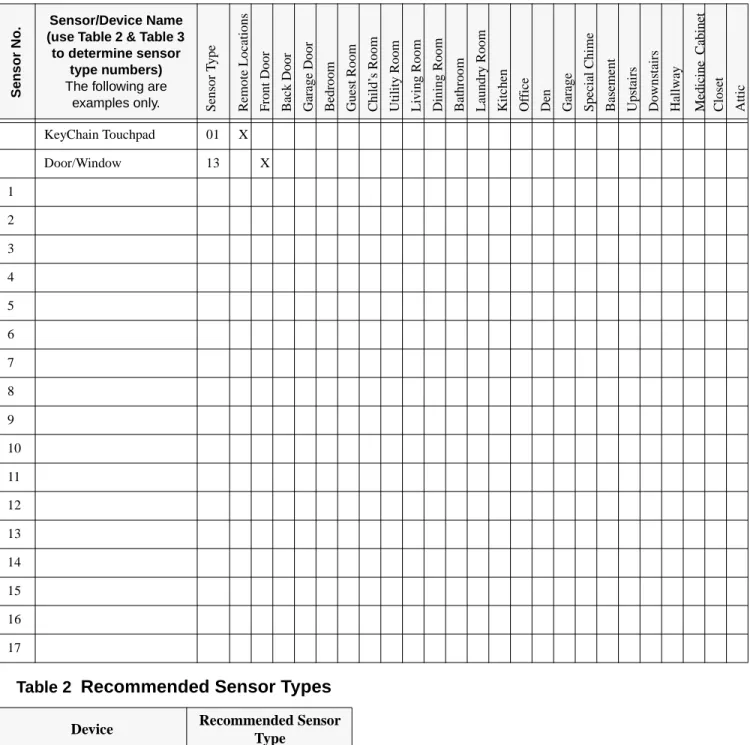
Table 1 Sensor/Device Location Planning Table Locations in order as communicated by Control Panel when changing sensors, except that Remote Locations are not used by the Control Panel, but only used here for
planning purposes. (This table is duplicated at the end of this manual)
S e ns or N o . Sensor/Device Name
(use Table 2 & Table 3 to determine sensor
type numbers) The following are
examples only. Sen
so r T y pe Remo te Lo ca tio n s Fr ont Do or Bac k Do or Garag e Do or B edr oo m Gue st Ro om Child’ s Roo m Ut ilit y Roo m Li vi ng Roo m D inin g R o om Bathr o o m L aun dr y R o om Kit chen Of fice Den Garag e Spe ci al C h im e Bas eme nt Upsta irs Down stairs Ha llwa y Me di ci ne C abi n et Cl os et At tic KeyChain Touchpad 01 X Door/Window 13 X 1 2 3 4 5 6 7 8 9 10 11 12 13 14 15 16 17
Table 2 Recommended Sensor Types
Device Recommended Sensor
Type
KeyChain Touchpad 01, 03, 06, 07 Remote Handheld Touchpad 01, 03, 06, 07
Indoor Motion Sensor 17 (intrusion), 25 (chime) Outdoor Motion Sensor 25
Smoke Sensor 26
Exterior Door 10 Interior Door 14
*This type is not certified as a primary protection circuit for UL-listed systems and is for supplementary use only.
§This type is required for UL-listed residential fire alarm applica-tions.
‡This type has not been investigated by UL. The arming levels are:
1 = Disarm
2 = Arm Doors & Windows 3 = Arm Motion Sensors
4 = Arm Doors/Windows & Motion Sensors
Delays:
I = Instant Delay (no delay, immediate alarm)
S = Standard Delay (alarm sounds after programmed entry delay time)
F = Follower Delay (alarm sounds immediately if entry/exit delay is not active, otherwise alarm sounds after programmed entry de-lay time)
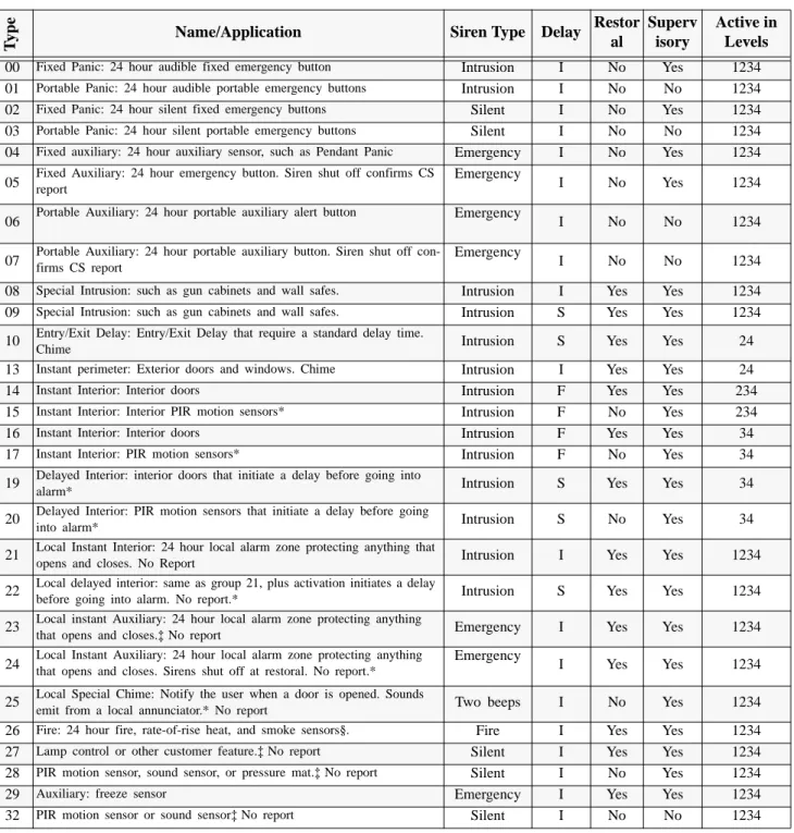
Table 3 Sensor Type Characteristics (This table is duplicated at the end of this manual)
Ty
p
e
Name/Application Siren Type Delay Restor
al
Superv isory
Active in Levels
00 Fixed Panic: 24 hour audible fixed emergency button Intrusion I No Yes 1234
01 Portable Panic: 24 hour audible portable emergency buttons Intrusion I No No 1234
02 Fixed Panic: 24 hour silent fixed emergency buttons Silent I No Yes 1234
03 Portable Panic: 24 hour silent portable emergency buttons Silent I No No 1234
04 Fixed auxiliary: 24 hour auxiliary sensor, such as Pendant Panic Emergency I No Yes 1234
05 Fixed Auxiliary: 24 hour emergency button. Siren shut off confirms CS report Emergency I No Yes 1234
06 Portable Auxiliary: 24 hour portable auxiliary alert button Emergency I No No 1234
07 Portable Auxiliary: 24 hour portable auxiliary button. Siren shut off con-firms CS report Emergency I No No 1234
08 Special Intrusion: such as gun cabinets and wall safes. Intrusion I Yes Yes 1234
09 Special Intrusion: such as gun cabinets and wall safes. Intrusion S Yes Yes 1234
10 Entry/Exit Delay: Entry/Exit Delay that require a standard delay time.
Chime Intrusion S Yes Yes 24
13 Instant perimeter: Exterior doors and windows. Chime Intrusion I Yes Yes 24
14 Instant Interior: Interior doors Intrusion F Yes Yes 234
15 Instant Interior: Interior PIR motion sensors* Intrusion F No Yes 234
16 Instant Interior: Interior doors Intrusion F Yes Yes 34
17 Instant Interior: PIR motion sensors* Intrusion F No Yes 34
19 Delayed Interior: interior doors that initiate a delay before going into
alarm* Intrusion S Yes Yes 34
20 Delayed Interior: PIR motion sensors that initiate a delay before going
into alarm* Intrusion S No Yes 34
21 Local Instant Interior: 24 hour local alarm zone protecting anything that
opens and closes. No Report Intrusion I Yes Yes 1234
22 Local delayed interior: same as group 21, plus activation initiates a delay
before going into alarm. No report.* Intrusion S Yes Yes 1234
23 Local instant Auxiliary: 24 hour local alarm zone protecting anything
that opens and closes.‡ No report Emergency I Yes Yes 1234
24 Local Instant Auxiliary: 24 hour local alarm zone protecting anything that opens and closes. Sirens shut off at restoral. No report.* Emergency I Yes Yes 1234 25 Local Special Chime: Notify the user when a door is opened. Sounds
emit from a local annunciator.* No report Two beeps I No Yes 1234
26 Fire: 24 hour fire, rate-of-rise heat, and smoke sensors§. Fire I Yes Yes 1234
27 Lamp control or other customer feature.‡ No report Silent I Yes Yes 1234
28 PIR motion sensor, sound sensor, or pressure mat.‡ No report Silent I No Yes 1234
29 Auxiliary: freeze sensor Emergency I Yes Yes 1234
Planning Control Locations
Control Panel
Locate the Control Panel so that the alarm sounds can be heard and it will be convenient to operate. It must be near an electrical outlet and telephone receptacle.
Remote Handheld Touchpad
Locate Remote Handheld Touchpads where they will be convenient and offer quick response in emergen-cies.
KeyChain Touchpad
KeyChain Touchpads attach to the owner’s key ring or can be conveniently carried.
Planning for Lamp, Appliance,
Wallswitch, and Universal/Garage
Door Module Control
As you program the modules, the Control Panel asks you to choose the house code, unit number and acti-vation method. Fill out Table 4, Home Control Plan-ning Table, before you begin programming.
The system can control 8 individual unit numbers on Lamp, Wallswitch, Appliance, and Universal/Garage Door Modules.
Setting the House Code and Unit
Num-ber
Each device controlled by the Control Panel must have an identification setting. The modules use two dials to set identification codes: one with letters A through P and one with numbers 1 through 16. The lettered dial sets the house code. The house code enables the system to differentiate this home from other homes in the area. Set all modules (except the remote siren) and the Control Panel to the same house code.
The numbered dial sets the unit number. The unit
number tells the system which device you want to control. Each unit number should be different (unless you want specific lights or appliances to be activated together). The Control Panel recognizes up to 8 unit numbers for sensor-activated, time-activated and en-try/exit delay lights. When unit numbers 9-16 are used for lamp modules, they can only be controlled by an all on or all off command.
A lamp will flash to the arming level if its unit number is set to 10. A lamp set to unit number 10 will flash once if the Control Panel is disarmed, twice if doors & windows are armed, etc.
The remote siren can be set to any unit number to hear alarm sounds. Set it to unit number 9 to hear arming level beeps, status beeps, and trouble beeps.
To Fill Out the Lamp Control Planning Table:
Note: Do not use a light module to control appliances, use an appliance module, since the wattage rating on Lamp Modules is less than on Appliance Modules.
1. Set the house code on all the Modules, except the remote siren to the same letter.
Set the Remote Siren house code to the next al-phabetical letter. For example, if the house code is B, set the remote siren’s house code to C. Note: The house code instructions which come with the Powerhorn Siren won’t work with this Control Panel. Follow the instructions given here.
2. Set the Module unit numbers.
Note: If you are using a Universal Module to operate a ga-rage door, make sure to assign a unique unit number to this Module choosing from 1-8.
3. List the location of the lamp or appliance in the Location column of Table 4.
4. Write the location of each Lamp Module on an adhesive note and label the module.
5. Decide if the device should be activated by sen-sors, entry/exit delay, time, or a combination. An example of sensor activation is using a motion sensor to turn on a light. Record the information in the appropriate columns.
Planning System Access Codes
Use the following to plan system Access Codes. Fill out Table 5 to use when programming these codes.
Utility Access Code 1
This access code is used during installation. The de-fault utility access code is 4321. This code can be used for all programming.
Utility Access Code 2
The default access code is 4321. This access code is used during for all programming except for changing utility access code 1 and changing options 4, 5, 6, 8, 9, 12, and 13.
Master Access Code
The default Master Access Code is 1234. This user code is needed to: disarm the Control Panel, program options 1 through 3, program light control, set the
sys-tem clock, program access codes 1-5, and perform a sensor or phone test. The use of the Master Access Code should be limited since it can delete and add the secondary access codes.
Access Codes (1 - 5)
The Control Panel can have up to 5 secondary user ac-cess codes. These could be used by children, a baby sitter, or a service person. These codes have the same programming privileges as the master access code ex-cept they cannot program access codes 1 - 5.
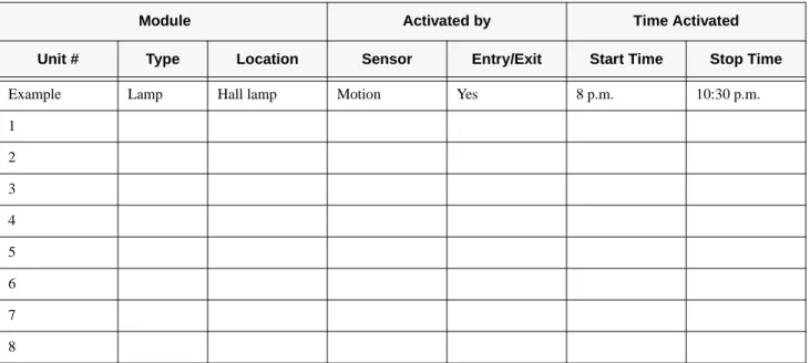
Table 4 Home Control Planning Table (This table is duplicated at the end of this manual)
Module Activated by Time Activated
Unit # Type Location Sensor Entry/Exit Start Time Stop Time
Example Lamp Hall lamp Motion Yes 8 p.m. 10:30 p.m.
1 2 3 4 5 6 7 8
Table 5 System Access Codes
Type Default Installer
Settings Utility Access Code 1 4321
Utility Access Code 2 4321 Master Access Code 1234
Access Code 1 None
Access Code 2 None
Access Code 3 None
Access Code 4 None
Planning System Options
Use the following to plan system Options. See Table 10 for a complete listing of all system options and their characteristics. Fill out the last column of this ta-ble to use when programming.
Option 01: Panel Beeps
Add turns on panel beeps that sound when an access
code is entered or when the arming level is changed.
Delete turns off panel beeps.
Option 02: Panel Voice
Add enables the panel’s voice. Delete disables the panel’s voice.
Note that the panel voice is always on for status mes-sages, open sensor responses, and when in program mode.
Option 03: Latchkey (Reports as 99)
Add programs the Latchkey time. If Latchkey is
en-abled, when the Control Panel is armed and the Con-trol Panel is not disarmed by the preprogrammed time, the Control Panel will call in a Latchkey alarm at the programmed time.
Delete removes the Latchkey time. Latchkey cannot
be enabled when the Control Panel is armed.
Option 04: Primary Phone Number
Add programs the primary phone number to be called
when there is an alarm. The phone number will call the central station.
Delete removes the primary phone number.
Option 05: Secondary Phone Number
Add and Delete function the same as they do for the
primary phone number. This number can be to a nu-meric pager or a central station. When using it to call a numeric pager, program this phone number with 2 pauses (press the test button to program a pause) at the end of the number. Set Phone Mod 2 (option 13) to 8 or 9. The Control Panel will call a numeric pager twice for each report. Pagers that require the Control
Panel to dial more than 18 digits will not work. Silent alarms report to a pager as an intrusion alarm. See the Owner’s Manual for more reporting information.
Option 06: Downloader Phone Number
Programs the ITI ToolBox Downloader telephone number.
Add and Delete function the same as they do for the
primary phone number.
Option 07: Account Number
Add programs the account number. Delete resets it to 00-000.
Option 08: Phone Lock
Add enables phone lock so that a different central
sta-tion cannot change the central stasta-tion code.
Delete disables phone lock.
Option 09: DL Code (Downloader Code)
Add programs the downloader access code. The
Downloader Code is used during Control Panel pro-gramming with the ITI ToolBox. The Control Panel’s downloader code must match the downloader access code in the ITI ToolBox account in order to program the Control Panel using the ITI ToolBox.
Delete resets it to 12345.
Option 10: Entry Delay
Add programs the entry delay. Enter time in seconds.
The range is 005-120 seconds (3 digits must be en-tered).
Delete sets the delay to 5 seconds.
For UL listed systems, the entry delay should not ex-ceed 45 seconds.
Option 11: Exit Delay
Add programs the exit delay. Enter time in seconds.
The range is 005-120 seconds (3 digits must be en-tered).
Delete sets the delay to 5 seconds.
For UL listed systems, the exit delay should not ex-ceed 45 seconds.
Option 12: Phone Mod 1
Add sets the report content and format which the
pri-mary phone number uses. The range is 0-3.
Delete sets the phone mod to 0.
Alarms include: Fire, Intrusion, Emergency, and Si-lent.
Non-Alarms include: Latchkey, No Activity, Alarm Cancel, Opening, Closing, Force Armed, AC Power Failure, CPU Low Battery, and Trouble Restorals. All includes: Alarms and Non-Alarms.
UL has only verified compatibility with the ITI CS4000 Digital Alarm Communicator Receiver.
Option 13: Phone Mod 2
Add sets the report content and format that the
second-ary phone number uses. Range is 0-9.
Delete sets the phone mod to 0.
Option 14: DTMF Dialing
Add enables DTMF dialing.
Delete enables pulse dialing.
Option 15: No Activity (Upper Sensor 79)
Add enables the no activity time-out. Program the no
activity time-out in hours. The range is 02-24 hours (2 digits must be entered).
Delete disables the no activity time-out.
Option 16: Auto Phone Test (Upper Sensor 93)
Add enables the auto phone test. Program the auto
phone test frequency in days. The range is 001 - 254 days (3 digits must be entered).
Delete disables auto phone test.
Option 17: Dialer Delay
Add enables the dialer delay. Program the delay in
seconds. The range is 005-120 seconds (3 digits must be entered).
Delete disables the dialer delay.
For UL installations, dialer delay time cannot be greater than 45 seconds.
Note: The Control Panel will not wait the programmed dial-er delay to call in an alarm if the Control Panel is disarmed before the dialer delay expires and opening reports are on. Both the alarm and opening report will be called in immedi-ately.
Option 18: Alarm Cancel
Add enables alarm cancel. Program the time in
min-utes. If the Control Panel is disarmed from an alarm state within the programmed time, the Control Panel will send an alarm cancel message. The range is 01-30 minutes (2 digits must be entered).
Delete disables the alarm cancel.
Option 19: Supervisory Time (SUPSYNC)
Add sets the supervisory time. Program the time in
hours. The range is 02-24 hours (2 digits must be en-tered).
Delete resets SUPSYNC to 2 hours.
For UL listed systems, the SUPSYNC shall not ex-ceed 4 hours.
Table 6 Phone Mod 1
Enter # Reports Format
0 All ITI
1 All 4/2
2 Alarms ITI
3 Alarms 4/2
Table 7 Phone Mod 2
Enter # Reports Form
at 0 All ITI 1 All 4/2 2 Alarms ITI 3 Alarms 4/2 4 Non-Alarms ITI 5 Non-Alarms 4/2
6 Phone 1 failure ITI
7 Phone 1 failure 4/2
8 Latchkey/No Activity/
Phone Test Pager
9 Alarms/Latchkey/No
Option 20: Manual Phone Test (Upper Sensor 83)
Add allows the user to perform a manual phone test. Delete disables manual phone test.
Option 21: Opening Reports (Upper Sensor 84)
Add enables opening reports. Opening reports will be
sent to the central station if the Control Panel is dis-armed from a higher arming level. Also, if the Control Panel is armed to level 4 from level 2 or 3, an opening report will be sent to the CS.
Delete disables opening reports.
Option 22: Closing Reports (Upper Sensor 85)
Add enables closing reports. Closing reports will be
sent to the central station if the Control Panel is armed to level 2, 3, or 4.
Delete disables closing reports.
Option 23: Force Armed (Upper Sensor 87)
Add enables force armed report. A force armed report
will be sent to the central station.
Delete disables force armed reports.
Option 24: AC Power Failure (Upper Sensor 90)
Add enables AC power failure reports. An AC power
failure report will be sent to the central station if the Control Panel has lost power for 15 minutes. The Control Panel will report AC power restoral when power returns to the Control Panel.
Delete disables AC power failure and restoral reports.
Option 25: CPU Low Battery (Upper Sensor 91)
Add enables CPU low battery reports. A low battery
report will be sent to the central station when the Con-trol Panel’s battery voltage drops below 7.65 volts.
Delete disables CPU low battery reports.
Option 26: Fail to Communicate (Upper Sensor 96)
Add enables fail to communicate. If the Control Panel
is not able to connect to the CS when it’s trying to re-port an alarm, the Control Panel will indicate this with trouble beeps and in the status message.
Delete disables fail to communicate.
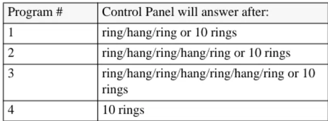
Option 27: Ring/Hang/Ring (Feature 01)
Add enables ring/hang/ring to use with ToolBox. This
feature is useful when programming a Control Panel in a home with an answering machine. Program ring/ hang/ring by number.
If ring/hang/ring is programmed as:
Program # 1 -
1. Call the Control Panel and let the phone ring twice then hang up.
2. Wait 10-40 seconds and call the Control Panel again.
3. The Control Panel should answer on the first ring.
Program # 2 - Repeat steps 1 & 2 before the Control Panel will answer.
Program # 3 - Repeat steps 1 & 2 twice before the Control Panel will answer.
Delete disables ring/hang/ring. The Control Panel
will not answer.
Option 28: No Delay from KeyChain Touchpad (Feature 32)
Add arms with no entry delay when using the
Key-Chain Touchpad.
Delete arms with an entry delay when using the
Key-Chain Touchpad.
Option 29: Control Panel Alarms
Add enables the Control Panel’s piezo. Alarms will
sound from the Control Panel.
Delete disables the Control Panel’s piezo. Alarms will
not sound from the Control Panel.
Table 8 Ring/Hang/Ring Program Numbers
Program # Control Panel will answer after: 1 ring/hang/ring or 10 rings
2 ring/hang/ring/hang/ring or 10 rings 3 ring/hang/ring/hang/ring/hang/ring or 10
rings
For UL listed systems, at least one listed external au-dible signal device shall be used if the external piezo is disabled.
Option 30: Panic Alarms
Add enables panic alarms initiated from the Control
Panel or Handheld Touchpad.
Delete disables panic alarms.
Option 31: Day of Week
Add will program the day of week based on a
pro-grammed number. The day of week will be used dur-ing an event buffer dump to ToolBox.
Delete sets day of week to 0.
Option 32: 300 Baud
Add enables 300 baud communication. Enable this
option for faster communication
Delete enables 110 baud communications.
Table 9 Day of Week by Number
0 Sunday 1 Monday 2 Tuesday 3 Wednesday 4 Thursday 5 Friday 6 Saturday
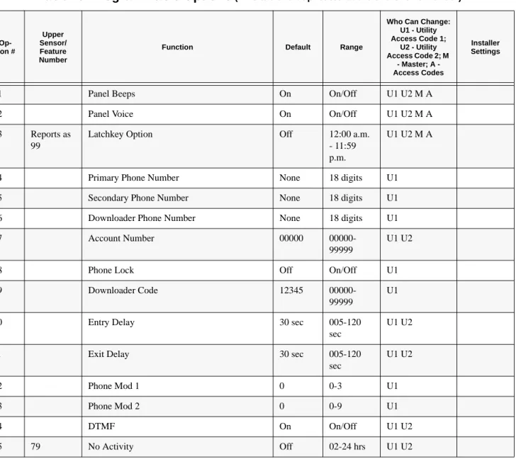
Table 10 Programmable Options(This table is duplicated at the end of this manual)
Op-tion # Upper Sensor/ Feature Number
Function Default Range
Who Can Change: U1 - Utility Access Code 1; U2 - Utility Access Code 2; M - Master; A - Access Codes Installer Settings
01 Panel Beeps On On/Off U1 U2 M A
02 Panel Voice On On/Off U1 U2 M A
03 Reports as 99
Latchkey Option Off 12:00 a.m.
- 11:59 p.m.
U1 U2 M A
04 Primary Phone Number None 18 digits U1
05 Secondary Phone Number None 18 digits U1
06 Downloader Phone Number None 18 digits U1
07 Account Number 00000
00000-99999
U1 U2
08 Phone Lock Off On/Off U1
09 Downloader Code 12345
00000-99999
U1
10 Entry Delay 30 sec 005-120
sec
U1 U2
11 Exit Delay 30 sec 005-120
sec U1 U2 12 Phone Mod 1 0 0-3 U1 13 Phone Mod 2 0 0-9 U1 14 DTMF On On/Off U1 U2 15 79 No Activity Off 02-24 hrs U1 U2
Wiring the Control Panel
This section describes how to:
• connect hardwire interior and exterior sirens (if
being installed)
• connect hardwire sensors
• connect the power transformer
• connect the backup battery
Connecting Hardwire Interior Sirens
The following ITI sirens may be used with this Con-trol Panel:
• Slimline Siren (60-483-01)
• LD105 Siren (13-374)
Follow the siren installation instructions included with the siren to connect a hardwire interior siren to the Control Panel.
16 93 Auto Phone Test Option (Must be enabled for UL Listed systems)
Off 001-254 days
U1 U2
17 Dialer Delay Off 001-120
sec
U1 U2
18 Alarm Cancel Off 01-30 min U1 U2
19 Supervisory Time (SUPSYNC) 12 hrs 02-24 hrs U1 U2
20 83 Manual Phone Test On On/Off U1 U2
21 84 Opening Reports Off On/Off U1 U2
22 85 Closing Reports Off On/Off U1 U2
23 87 Forced Arm Off On/Off U1 U2
24 90 AC Power Failure (Must be enabled for UL Listed systems)
Off On/Off U1 U2
25 91 CPU Low Battery (Must be enabled for UL Listed systems)
On On/Off U1 U2
26 96 Fail to Communicate (Must be enabled for UL Listed systems)
On On/Off U1 U2
27 Feature 01 Ring/Hang/Ring Off 1-4 U1 U2
28 Feature 32 No Delay from KeyChain Touchpad Off On/Off U1 U2
29 High Level Siren On On/Off U1 U2
30 Panic Alarms On On/Off U1 U2
31 Day of Week 0 0-6 U1 U2
32 300 Baud Central Station Communications Off On/Off U1 U2
Table 10 Programmable Options(This table is duplicated at the end of this manual)
Op-tion # Upper Sensor/ Feature Number
Function Default Range
Who Can Change: U1 - Utility Access Code 1; U2 - Utility Access Code 2; M - Master; A - Access Codes Installer Settings
Connecting a Hardwire Exterior Siren
Use only the model 13-046 Hardwire Exterior Siren as shown in Figure 2.
Figure 2. Exterior Siren Control Panel Connections
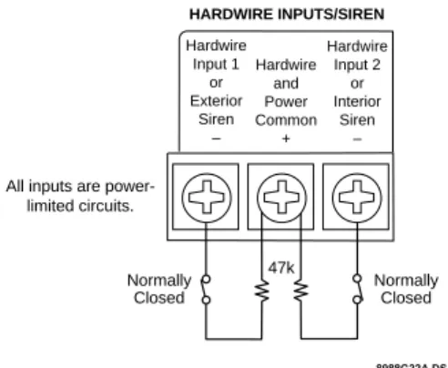
Connecting Hardwire Sensors
This section shows how to wire hardwire sensors to the Control Panel. For more detailed information on installing hardwire devices, see the installation in-structions that accompany each device. Wire sensors to be supervised by using a 47k Ohm resistor (includ-ed with the Control Panel).
Figure 3. Wire Hardwire Sensors Normally Closed
Connecting the Universal/Garage
Door Opener Module
Use the following to connect a universal module to be used to open a garage door:
1. Set the unit code of the universal module to a unique unit number between 1 and 8.
2. Set the house code to the house code for the installation.
3. Set the module’s switches to momentary and relay only.
4. Connect the terminals on the universal
mod-ule to the button terminals on the garage door
opener.
5. Plug the universal module into a wall outlet.
Note: See the Programming Light and Appliance Controls section to program a KeyChain Touchpad to open a garage door.
Connecting the Power Transformer
Connect the power transformer as shown in Figure 4. Plug the transformer into an unswitched outlet.
Figure 4. Power Transformer Control Panel Con-nections 8988G20A.DS4 HARDWIRE EXTERIOR SIREN PART NO. 13-046 RED BLACK
All inputs are power-limited circuits. AC POWER Hardwire Input 1 or Exterior Siren – HARDWIRE INPUTS/SIREN Hardwire and Power Common + Hardwire Input 2 or Interior Siren – 9 VAC 8988G22A.DS4
All inputs are power-limited circuits. Hardwire Input 1 or Exterior Siren – HARDWIRE INPUTS/SIREN Hardwire and Power Common + Hardwire Input 2 or Interior Siren – Normally Closed 47k Normally Closed 8988G03A.DS4 CLASS II POWER TRANSFORMER PART NO. 22-091
All inputs are power-limited circuits. AC POWER Hardwire Input 1 or Exterior Siren – HARDWIRE INPUTS/SIREN Hardwire and Power Common + Hardwire Input 2 or Interior Siren – 9 VAC
Connecting the Backup Battery
Connect a 9-Volt lithium battery (ITI #34-037) to the battery clips (see Figure 5.).
Figure 5. Control Panel Battery Installation
Note: The Control Panel wil initially indicate a low battery by lighting the SYSTEM STATUS button. If this button is pressed the Control Panel will announce, System low bat-tery.
The Control Panel does a battery test every 4 hours and will clear the status message if the battery is good. Perform a sensor test, see the Testing Sensors section, to perform an immediate battery test.
Connecting the Phone Line to the
Control Panel
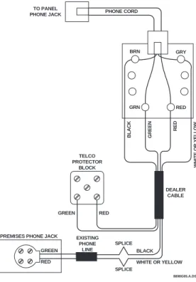
If the system will be monitored by a central monitor-ing station, you must install an RJ-31X jack between the telephone company (TELCO) block and the Con-trol Panel. The jack must be located within 5 feet of the Control Panel.
Installing an RJ-31X Jack
Install and wire the RJ-31X jack as shown in Figure 6.
Figure 6. RJ-31X Wiring Diagram
Connecting the Phone Line to the
Con-trol Panel
1. Plug one end of the phone cord (included with the Control Panel) into the RJ-31X jack. 2. Plug the other end of the phone cord into the
Control Panel phone jack.
3. When looking at the back of the Control Panel, the top block is used to connect the phone to the Control Panel and the bottom block is used to connect the Control Panel to the wall phone jack. 8959G17B.DS4 9 VOLT BATTERY BRN GRY GRN RED DEALER CABLE TELCO PROTECTOR BLOCK W H IT E OR YELLOW BL ACK GREEN GREEN RED RED BLACK WHITE OR YELLOW SPLICE SPLICE
PREMISES PHONE JACK EXISTING
PHONE LINE PHONE CORD TO PANEL PHONE JACK GREEN RED 8898G05.A.DS4
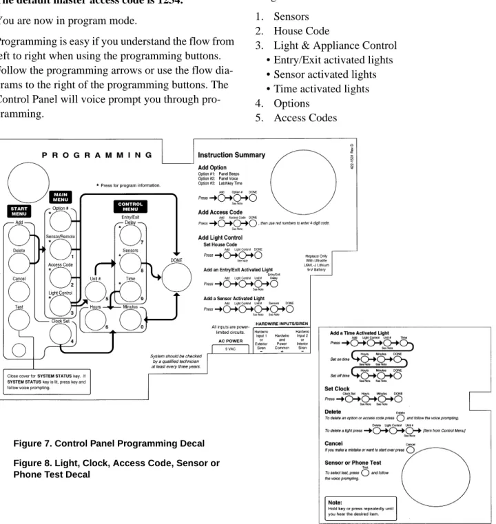
Programming Overview
These instructions tell you how to set up for program-ming and to put the Control Panel in program mode. 1. Arrange the sensors, modules, Control Panel,
and user controls on a table.
2. Open the Control Panel cover.
3. Enter Utility Access Code 1 (default is 4321) using red numbered keys.
The default for utility access codes 1 and 2 is 4321. The default master access code is 1234.
You are now in program mode.
Programming is easy if you understand the flow from left to right when using the programming buttons. Follow the programming arrows or use the flow dia-grams to the right of the programming buttons. The Control Panel will voice prompt you through pro-gramming.
Figure 7. Control Panel Programming Decal Figure 8. Light, Clock, Access Code, Sensor or Phone Test Decal
To get you started:
1. Press Add or Delete from the Start Menu. 2. Press Option #, Sensor/Remote, Access Code
or Light Control from the Main Menu.
The system response at this point depends upon what button you just pressed. Follow the voice prompts and programming arrows to continue.
Program the Control Panel in this order: 1. Sensors
2. House Code
3. Light & Appliance Control • Entry/Exit activated lights • Sensor activated lights • Time activated lights 4. Options
Programming Sensors
These instructions show you how to program sensors, touchpads and other system devices into the Control Panel.
Program sensors and devices before you install them. The Control Panel recognizes a sensor when you press the sensor’s program button or tamper switch. Table 11 describes the programming button location for each device.
Note: Sensor installation instructions included in this man-ual are for SAW devices only. This security system has a SAW receiver. When installing crystal sensors (non-SAW devices), use the installation instructions included in their packing boxes.
The Control Panel uses an ascending numbering se-quence (beginning with 1) when adding (learning) sensors. You may override the system suggested sen-sor number by using the red numbered keys.
Use Table 1, which was filled out during the system planning, to help program sensors.
To add a hardwire or RF sensor or remote control:
1. Press Add from the Start menu.
2. Press the Sensor/Remote button from the Main menu until you hear the room name or item you want to add. The order of names the Control Panel uses are: keychain remote, touchpad remote, front door, back door, garage door, bed-room, guest bed-room, child’s bed-room, utility bed-room, liv-ing room, dinliv-ing room, bathroom, laundry room,
kitchen, office, den, garage, special chime, base-ment, upstairs, downstairs, hallway, medicine cabinet, closet, attic. Each name may be used more than once.
3. Press DONE when you hear the name you wish to add.
Note: When adding sensors, if you wish to use a more de-scriptive location you may press the option button to use the compass directions (north, north east, east, south east, south, south west, west, north west).
4. Enter the 2 digit sensor type using Table 1, with the red numbered keys.
Note: If you wish to use a sensor number other than the next available, enter a 2 digit sensor number with the red numbered keys immediately after entering the sensor type. 5. Press the sensor’s program button or tamper
button. Open the switch of hardwired sensors. The Control Panel verbally confirms your pro-gramming.
To delete sensors:
1. Press Delete from the Start menu.
2. Press Sensor/Remote from the Main menu until you hear the name you want to delete.
3. Press DONE. The system confirms the item you removed.
Programming the House Code and
Unit Numbers
Lamp Modules, Appliance Modules, and Remote Si-rens use the existing electrical wiring in the home to receive signals from the Control Panel. Since there are no direct wire connections required, any number of modules can be plugged into available outlets and installed in the system. All Lamp Modules and Appli-ance Modules have a common house code that allows modules to be identified by eight different control ad-dresses.
The house code allows adjacent homes that have a common power source to co-exist. The available house code choices are from A to O.
Table 11 Device Program Buttons
Device Program Button Location
Door/Window Sensor On top of sensor (cover removed)
Motion Sensor On back of sensor (mounting plate removed)
KeyChain Touchpad Lock & Unlock buttons Remote Handheld
Touch-pad
EMERGENCY buttons (to be used for non-medical emergen-cies)
Hardwire Sensors See individual sensor installa-tion instrucinstalla-tions
To program the house code:
1. Press Add from the Start menu.
2. Press Light Control from the Main menu until you hear the house code letter you want. 3. Press DONE.
4. Set the house code on each lamp and
appli-ance module using a screwdriver.
5. Set house code on the remote siren to the next alphabetical letter greater than the house code. All Lamp Modules with the same house code will turn on or flash as a group on alarm or when operating the “Light” button on a KeyChain Touchpad. The units must be identified with a unique unit number, from 1-8, to individually operate lights and appliances from a Remote Handheld Touchpad or to selectively pro-gram lights to go on during the entry/exit delay, to be operated by a sensor or at scheduled times.
To assign a unit number:
1. See Table 4 for your planning information. 2. Set the Unit number switch on each module.
Programming Light and Appliance
Controls
Use Table 4, which was filled out during the system planning, to help program control modules.
To add an entry/exit activated light:
1. Press Add from the Start menu.
2. Press Light Control from the Main menu. 3. Press Unit # until you hear the number you chose
on the module.
4. Press Entry/Exit Delay from the Control menu. The Control Panel confirms your programming.
To add a sensor-activated light:
1. Press Add from the Start menu
2. Press Light Control from the Main menu. 3. Press Unit # until you hear the number you chose
on the module.
4. Press Sensors from the Control menu until you hear the sensor you want to control the light.
5. Press DONE. The Control Panel confirms your programming.
Note: A KeyChain Touchpad can be programmed to a unit number. Press the star button to activate a light or open/ close a garage door using the Universal Module.
To add a time-activated light:
1. Press Add from the Start menu.
2. Press Light Control from the Main menu. 3. Press Unit # until you hear the unit number you
chose on the module.
4. Press Time from the Control menu.
5. Press Hours and Minutes to set the beginning of the schedule.
6. Press DONE.
7. Press Hours and Minutes to set the end of the schedule.
8. Press DONE. The system confirms your pro-gramming.
To delete an Entry/Exit-activated light:
1. Press Delete from the Start menu.
2. Press Light Control from the Main menu. 3. Press Unit # until you hear the unit number you
want to delete.
4. Press Entry/Exit Delay. The system confirms your programming.
To delete a sensor-activated light:
1. Press Delete from the Start menu.
2. Press Light Control from the Main menu. 3. Press Unit # until you hear the unit number you
want to delete.
4. Press Sensors from the control menu until you hear the one you want to delete.
5. Press DONE. The system confirms your pro-gramming.
To delete a time-activated light:
1. Press Delete from the Start menu.
2. Press Light Control from the Main menu. 3. Press Unit # until you hear the unit number you
want to delete.
Programming Options
Use Table 10, which was filled out during the system planning, to help program options.
There are two ways to enter options. They are as fol-lows:
• Press Add and press the Option # button until
you hear the option to be changed.
or--• Press Add and enter the option number you
want to program with the red numbered keys. The following instructions use the second method.
To set system options 01 and 02:
1. Press Add from the Start menu.
2. Press Option # and 01 or 02 with the red num-bered keys.
3. Press DONE.
To set system option 03:
1. Press Add from the Start menu. 2. Press Option # 03.
3. Press Hours and Minutes to set the time. 4. Press DONE.
To set system options 04, 05, and 06:
1. Press Add from the Start menu. 2. Press Option # and 04, 05, or 06.
3. Enter a phone number with the red numbered keys. Press Test to enter a pause in the phone number.
Note: The phone number is automatically stored after you’ve pressed 18 digits. You will not have to press DONE to store the number. If the number is less than 18 digits, then DONE must be pressed.
To set system option 07:
1. Press Add from the Start menu. 2. Press Option # 07.
3. Enter the account number. 4. Press DONE.
To set system option 08:
1. Press Add from the Start menu. 2. Press Option # 08.
3. Press DONE.
To set system options 09:
1. Press Add from the Start menu. 2. Press Option # 09.
3. Enter the downloader code. 4. Press DONE.
To set system options 10 & 11:
1. Press Add from the Start menu. 2. Press Option # 10 or 11.
3. Enter the delay times in seconds (3 digits must be entered).
To set system options 12 & 13: 1. Press Add from the Start menu. 2. Press Option # and 12 or 13. 3. Enter phone mod number.
To set system option 14:
1. Press Add from the Start menu. 2. Press Option # 14.
3. Press DONE.
To set system option 15 (Upper Sensor 79):
1. Press Add from the Start menu. 2. Press Option # 15.
3. Enter the no activity time out (2 digits must be entered).
To set system option 16 (Upper Sensor 93):
1. Press Add from the Start menu. 2. Press Option # 16.
3. Enter the number of days between each auto phone test (3 digits must be entered).
To set system option 17:
1. Press Add from the Start menu. 2. Press Option # 17.
3. Enter the dialer delay in seconds (3 digits must be entered).
To set system option 18:
1. Press Add from the Start menu. 2. Press Option # 18.
3. Enter the alarm cancel time in minutes (2 dig-its must be entered).
To set system option 19:
1. Press Add from the Start menu. 2. Press Option # 19.
3. Enter the supervisory time in hours (2 digits must be entered).
To set system options 20 - 26, 28 - 30, and 32:
1. Press Add from the Start menu. 2. Press Option # XX.
3. Press DONE.
To set system option 27:
1. Press Add from the Start menu. 2. Press Option # 27.
3. Enter the ring/hang/ring number.
To set system option 31:
1. Press Add from the Start menu. 2. Press Option # 31.
3. Enter the day of week number. To delete options:
1. Press Delete from the Start menu.
2. Press Option from the Main menu until you hear the name you want to delete.
3. Press DONE. The system confirms the item you removed.
Programming System Access Codes
Use Table 5, which was filled out during the system planning, to program system Access Codes.
To add a code:
1. Press Add from the Start menu.
2. Enter the access code as prompted by the panel voice by using the red numbered keys.
3. Press the Add button.
4. Press the Access Code button. Continue pressing the Access Code button until you hear the access code to be changed.
5. Press DONE.
6. Enter the new access code by using the red numbered keys.
The Control Panel says, code name is XXXX (the new 4 digit access code).
To delete a code:
1. Press Delete from the Start menu..
2. Press the Access Code button. Continue pressing the Access Code button until you hear the access code to be deleted.
3. Press DONE.
The Control Panel says, code name is deleted.
Installing the System
Control Panel
General Information
Do not install the Control Panel near a window or door where it can be reached easily by an intruder. Control Panels should be installed in locations where they are most likely to be heard.
Metal objects, mirrors, and metallic wallpaper can block signals sent by the wireless sensors. Make sure there are no metal objects in the way when installing the system.
The system will prompt you through programming steps with beeps and voice messages. If you need more time before proceeding, simply close the Con-trol Panel cover until you are ready to continue. When the cover is closed, the Control Panel is in the operating mode. Each time you close the Control Pan-el cover, a series of beeps will indicate the system sta-tus:
• One beep indicates the system is disarmed.
• Two beeps verify that Door/Window sensors are
armed.
• Three beeps verify that Motion Sensors are
armed.
• Four beeps verify that both Door/Window and
Motion sensors are armed.
The system cannot work without power. If the electri-cal power fails and the Control Panel battery is weak or dead, the system will not work.
Control Panel Specifications
Power Requirements: 9 VAC, 700 mA
Backup Battery: 9 VDC 1.2 AH UltraLife Lithium Radio Frequency: 319.5 MHz + or - 140 kHz Nominal Range: 500 feet, open-air receiving range Operating Temperature Range: 32°-122 ° F
(0°-50° C)
Maximum Humidity: 85% relative humidity,
non-condensing
Auxiliary Power Output: Regulated & unregulated,
fused 12 VDC at 250 mA (maximum)
Installation Guidelines
Use the following procedure to mount the Control Panel to the wall or wall studs, using the supplied mounting hardware and the panel mounting holes.
Materials Needed
• Pencil
• Hammer
• Screwdriver
To mount the panel:
1. Choose a spot within a few feet of an electrical outlet (the outlet should not be controlled by a wall switch) and also within reach of a telephone jack. The Control Panel can be placed on a desk, tabletop, or it can be wall mounted.
2. Open the Control Panel cover and position on the wall.
3. Mark the screw hole locations with a pencil. 4. Start holes with the tip of the screwdriver or a
nail.
5. Tap the wall anchors provided into the holes. 6. Insert the screws and partially tighten with the
screwdriver.
7. Hang the Control Panel on the screws and tighten securely.
8. Remove the center screw from the outlet cover plate.
9. Position the transformer so that its screw hole is
aligned with the screw hole on the outlet cover plate. Then plug the transformer into the outlet. 10. Replace the screw, and use it to secure the
trans-former to the outlet cover plate. Tighten the screw firmly with your screwdriver.
Testing the Control Panel
Test the Control Panel by pressing the buttons as de-scribed below:
• ARM Doors & Windows-The Control Panel
arms Doors & Windows. Press twice to eliminate the preprogrammed entry delay. The button will blink when No Entry Delay is on.
• ARM Motion Sensors-The Control Panel will
arm Motion Sensors. Press twice to turn Latch-key on. The button blinks when LatchLatch-key is on.
• DISARM -The Control Panel will disarm Doors,
Windows, and Motion Sensors when also enter-ing the appropriate access code.
• SYSTEM STATUS-Press to determine system
status and system time.
• CHIME Doors-Press to enable Control Panel
beeps which will sound when a protected door or window, that is programmed as sensor type 10 or 13, is opened.
• CHIME Special Motion- Press to enable Control
Panel beeps which will sound when a Motion Sensor, that is programmed as sensor type 25, is activated.
• LIGHTS Time Activated-Press to enable system
controlled lights to turn on/off at a scheduled time.
• LIGHTS Sensor Activated-Press to enable
sys-tem controlled lights to turn on for 4 minutes when a specific sensor is tripped.
• EMERGENCY-Press and hold or press twice
quickly to activate a non-medical emergency alarm.
Door/Window Sensor
General Information
Door/Window Sensors can be installed on doors, win-dows, or many other objects that open and close. The sensors transmit signals to the Control Panel when a magnet mounted near the sensor is moved away from or closer to the sensor.
Specifications
• Power supplied by: 2 AAA Alkaline batteries
• Dimensions: L = 4.5” X W = 1.2” H = .94”
• Typical battery life: 4-6 years
• Operating temperature range: 10° to 120° F
Installation Guidelines
Use the following guidelines for installing Door/Win-dow sensors.
• Mount the sensor on the door frame and the
mag-net on the door. If the sensor is to be used on double doors, mount the sensor on the least-used door and the magnet on the other door.
• Make sure the alignment arrow on the magnet
points to the alignment mark on the sensor.
• Place sensors at least 5 inches above the floor to
avoid damaging them.
• Avoid mounting sensors in areas where they will
be exposed to moisture or where the operating temperature (10°-120°)F will be exceeded.
• Use spacers (not included) to keep sensors and
magnets away from metal or metallic surfaces such as foil wallpaper.
Materials Needed
• #6 flathead screws
• Screwdriver or brad driver
The following illustrations and procedure describe how to install the Door/Window sensor
.
Figure 9. Sensor and Magnet Positions .
Figure 10. Aligning the Door/Window Sensor and Magnet
To install Door/Window sensors:
1. Remove the sensor cover by pressing the button on the narrow end.
2. Remove the circuit board to access the mounting holes.
3. Mount the sensor base with two #6 flathead screws at the locations shown in Figure 11.
Figure 11. Mounting Hole Locations (Bottom View) 4. Remove the magnet from its base. Line up the
arrow on the magnet with the mark on the sensor. 5. Mount the magnet base no more than 3/8-inch
away from the sensor base. Replace the magnet cover.
8888G01A.DS4 MOUNTING HOLES
6. Re-install the batteries and attach the sensor cover to the sensor base.
Note: When window or door construction does not allow the transmitter to be installed next to the magnet, use an ex-ternal switch to install the Door/Window Sensor.
Connecting External Switches
External switches used with Door/Window Sensors allow you to protect doors and windows when there is inadequate room for directly mounting the sensor or when you want to locate the Door/Window Sensor in an adjacent but less visible place.
Materials Needed
• Hermetically sealed external switches (sealed
reed switch) that supply a minimum 250-milli-second open or closure on alarm
• Stranded 22-gauge wire
Installation Guidelines
1. Install the magnet on the opening edge of the door or movable part of a window.
2. Position the switch on the door or window frame within one inch of the magnet.
3. Remove the cover from the Door/Window Sen-sor.
4. Pass the wires on the adapter through the rear opening at the bottom of the Door/Window Sen-sor.
5. Attach each wire to one side of the screw termi-nal. Press the screw terminal over the wire posts. 6. Mount the transmitter.
Testing Door/Window Sensors
The following steps describe the guidelines for testing sensors.
1. Open the Control Panel cover. 2. Enter Utility Access Code 1 or 2. 3. Press Test.
4. Press DONE.
5. Trip the sensor (move the magnet away from the sensor) and do not replace the magnet until the Control Panel indicates the number of RF packets received.
6. Note the number of siren beeps indicating how many RF packets the Control Panel received from the sensor. You should hear 7-8 beeps. The Control Panel will also say, Status is X (X = num-ber of RF packets).
Indoor Motion Sensor
General Information
Both the indoor motion sensor and the outdoor motion sensor are Passive InfraRed (PIR) Motion Sensors. They are designed to detect movement within a spe-cific area by sensing the infrared energy emitted from a body as it moves across the sensor’s field of view causing the temperature to change in the sensor’s zones. When motion is detected the unit sends an alarm signal to the Control Panel.
Use motion sensors to protect locations where door/ window sensors are impractical or not needed. For ex-ample, use a motion sensor to protect large areas or open floor plans. Motion sensors also provide backup protection for door/window sensors.
The Indoor & Outdoor Motion Sensors:
• Area of coverage is 35 feet by 40 feet for
Stan-dard and Animal Alley lenses
• Masking kit provided to block portions of
cover-age area
• Three minute transmitter lockout time after an
alarm extends battery life
• Cover-activated Tamper (optional wall-activated
Tamper is included)
• The sensor transmits low battery report (trouble)
to the Control Panel
• The sensor transmits supervisory signal to the
Control Panel every 64 minutes
• Field-selectable sensitivity options of standard or
high
Specifications
• Power supplied by: 2 AA Alkaline batteries
• Dimensions: L = 2.875” X W =2.375” X H =
• Typical battery life: 3 - 4 years (has not been ver-ified by U.L.)
• Operating temperature range: 32° to 120° F
Installation Guidelines
Use the following guidelines for installing indoor mo-tion sensors.
1. For best coverage, mount the sensor from 5 to 8 feet high in the corner of the area you want to protect. See the Animal Alley lens guidelines for mounting the Animal Alley lens. Higher mount-ing provides better range (up to 35 feet), and lower mounting provides better protection close to the motion sensor. See Figure 13. and Figure 14.
2. Position the sensor to protect an area where an intruder would be most likely to walk across the detection pattern. See Figure 12.
.
Figure 12. Overhead (Bird’s Eye View) Detection Path
3. Mount the motion sensor on an insulated outside wall facing in.
4. Mount the motion sensor on a rigid surface which is free from vibrations.
5. Position the sensor so it faces a solid reference point, like a wall.
6. Do not aim the sensor at windows, fireplaces, air conditioners, area heaters, forced air heating vents, or place it in direct sunlight. Sudden
changes in temperature may trigger a false alarm from these devices.
7. Do not mount the sensor near duct work or other large metallic surfaces which may affect the RF signals (see RF Testing). Actual acceptable trans-mitter range should be verified for each installa-tion.
8. Mount the sensor permanently on a flat wall or in a corner. Do not set it on a shelf.
9. Windows should be closed in any area which has an armed motion sensor.
10. A pet will trigger a motion sensor. See Animal Alley lens guidelines to use a motion sensor when pets are present.
Figure 13. Top View Shows Both Standard & Ani-mal Alley Lens Coverage Area. Side View Shows the Coverage Area Using the Animal Alley Lens
8362G07B.DS4 8 ft0 m 4 ft 0 ft 0 ft 35 ft 11 ft 2.4 m 1.2 m 0 m 0 ft 20 ft 20 ft 0 ft 10 ft 20 ft 0 m 11 m 6 m 3 m 0 m 3 m 6 m 35 ft TOP VIEW
(STANDARD AND ANIMAL ALLEY LENS)
SIDE VIEW (ANIMAL ALLEY LENS)
Figure 14. Side Views Show the Differences in the Coverage Area when using the standard lens mounted at Different Heights.
Mounting Procedure for Indoor Motion Sensors:
Surface, Corner, or Inclined Mounting, see Figure 14. showing these 3 mounting positions:
1. Remove the mounting plate by depressing the button on the top of the sensor body. With the opposite hand pull the mounting plate away from the body of the sensor.
2. Punch out the mounting holes that best fit your application. See Figure 15. for wall mount options. See also Figure 16. to determine which knockouts to use when mounting the motion sen-sor. Use the lower-side holes for corner mount-ing, or the lower-back holes for surface mounting with the standard lens.
3. Mark the location of the required holes on the mounting surface.
4. Use wall anchors and screws to secure into place.
Figure 15. Wall Mount Options: use the inclined position for surface or corner mounting with the standard lens. Use the flush position for surface or corner mounting with the animal alley lens.
Figure 16. PIR Mounting Plate Knockouts. Use the Wall Tamper Knockout only if tampering at the wall Note: For applications without pets, use the lower mounting holes. For applications with pets, use the upper mounting holes and the animal alley lens (ITI # 13-381).
5. If you desire wall tamper functionality, remove the wall tamper knock-out (see Figure 16.). The wall tamper switch cannot be used when the
sen-8362G09A.DS4 8 ft0 m 4 ft 0 ft 35 ft 11 ft 2.4 m 1.2 m 0 m SIDE VIEWS (STANDARD LENS)
7 1/2 FOOT MOUNTING HEIGHT
0 ft 8 ft0 m 4 ft 0 ft 0 ft 35 ft 11 ft 2.4 m 1.2 m 0 m 5 FOOT MOUNTING HEIGHT
8362G03A.DS4
FLUSH MOUNT INCLINED MOUNT
CORNER MOUNT
USE WITH STANDARD LENS
USE WITH ANIMAL ALLEY LENS
8362G01B.DS4 WALL
TAMPER KNOCKOUT