1
Single Axis Solar Panel Tracking Mount Using Stepper
Motor and Accelerometer Positional Control
Author: Ezra Pramono
Faculty Advisor: Prof. Dale Dolan
Senior Project
ELECTRICAL ENGINEERING DEPARTMENT
California Polytechnic State University
San Luis Obispo
2
Table of Contents
Chapter 1: Abstract ... 4
1.1: Introduction ... 4
1.2: Customer Needs, Requirements, and Specifications ... 5
1.3: Functional Decomposition ... 6
1.4: Project Planning ... 8
Chapter 2: System Design and Construction ... 10
2.1: Mechanical Structure ... 10
2.2: Stepper Motor and Motor Driver ... 11
2.3: Accelerometer Angle Measurement ... 12
2.4: Microcontroller and Feedback Control ... 14
Chapter 3: System Performance ... 15
3.1: Performance Testing ... 15
3.2: Expense Tracking... 16
Chapter 4: Conclusion ... 18
4.1: Accomplishments ... 18
4.2: Improvement Opportunities ... 18
References ... 19
Appendices ... 21
Appendix A. Source Code ... 21
3
List of Tables and Figures
Table Page
1. Single Axis Solar Panel Tracker Requirements and Specifications……….………5
2. Single Axis Solar Panel Tracker Deliverables……….6
3. Single Axis Solar Panel Tracker Inputs and Outputs………..………….6
4. Gantt Chart (Fall 2019) ……….……..….8
5. Gantt Chart (Winter 2020) ……….….……….8
6. Gantt Chart (Spring 2020) ……….….………….9
7. Cost Estimates……….………….9
8. Medium Increment Positioning Test………..……15
9. Small Increment Positioning Test………...…16
10.Expenses (Actual)………..…17
Figures Page 1. Single Axis Solar Tracker Level 0 Block Diagram……….7
2. Single Axis Solar Tracker Level 1 Block Diagram……….7
3. CAD Model of Extruded Aluminum Frame………..……….…11
4
Chapter 1: Abstract
Optimal solar panel systems rotate to track the sun, as solar panels operate at their maximum potential when the panel plane is completely normal to the sun’s rays. These tracking systems often using two axes of movement. This project is to design a system that will allow a solar panel to track the sun using only one rotational axis, which saves energy and uses fewer parts. The system tracks the entire range of the sun's motion and has positional feedback to allow control of the solar panel's angle. The position of the tracking system is controllable via an external computer. The goal of this project is to construct a solar tracking device that accurately tracks the sun in order to maximize the energy output of the solar panel.
1.1: Introduction
I selected the project based on its focus on control systems and mechatronics, with some components of digital signal processing and power electronics. The project mainly revolves around motor control and the interpretation of digital control signals. It is somewhat related to a separate senior project in which the algorithm for maximizing the power output of a single axis tracking solar panel is developed. The project will experiment with solar tracking algorithms to optimize solar energy output in a manner similar to the research done in [7] and [10]. This project focuses on building the hardware systems that will be controlled by this algorithm.
While single axis solar panels are not a new development and are a well established part of the solar industry, the goal of this project is to build a single axis solar tracker for laboratory use, in order to optimize and test solar tracking algorithm. The project will include an
exploration of the PID control systems (as demonstrated in [11]) and microcontroller processes (as demonstrated in [5], [9], [12]) previously used by other researchers to control solar panel trackers. Through top-down design of the solar tracking device, the hope is to explore unique methods for actuating the solar panel and controlling position, which may be more efficient or more accurate than other systems.
The project mainly encompasses class material from control systems classes such as EE302, as well as embedded computing for the microcontroller and signal processing (CPE329). There will also be electronics design tasks utilizing material from EE409. The motor control aspects of the project will be related to motor and power classes such as EE255/295. The project will require additional knowledge and techniques not covered by course material such as PCB design, CAD, and solar power simulation.
5 1.2: Customer Needs, Requirements, and Specifications
Customer Needs Assessment
The customer specified that the solar panel tracking system must be single axis. There are a wide variety of solar panel makes and models the end user may mount to the tracker, therefore the device must have mounting options and a weight capacity suitable for most types of solar panels. The customer also requested a -90° to 90° range of rotation to fully track the sun’s movement in order to track the sun from sunrise to sunset.
Requirements and Specifications
The tracking module would ideally have a -90° to 90° range of movement in order to track the sun’s full range of movement throughout the day. Also, tracking the sun, by definition, requires that the device rotates the solar panel fast enough to keep up with the sun’s movement.
Since this project does not encompass the control system and tracking algorithm, it must be able to communicate with an external device to control its movement. While the goal of the project is to create a tracking system that consumes as little power as possible, there should be a
benchmark of 10% relative to the solar panel’s maximum power output. For the tracker to achieve a net gain in power output, its power consumption must be small compared to the increase in efficiency it causes. The solar panel tracker must be able to function for long periods outdoors, requiring a certain degree of water and dust resistance as has been researched in [4]. Table 1 below describes each engineering specification and which marketing requirement each one fulfills.
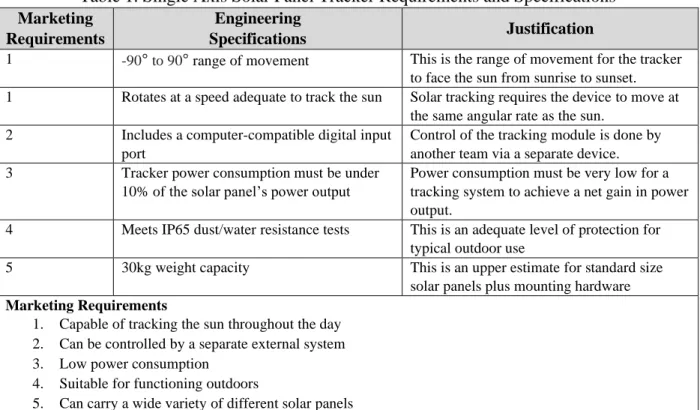
Table 1. Single Axis Solar Panel Tracker Requirements and Specifications Marketing
Requirements
Engineering
Specifications Justification
1 -90° to 90° range of movement This is the range of movement for the tracker to face the sun from sunrise to sunset. 1 Rotates at a speed adequate to track the sun Solar tracking requires the device to move at
the same angular rate as the sun. 2 Includes a computer-compatible digital input
port
Control of the tracking module is done by another team via a separate device. 3 Tracker power consumption must be under
10% of the solar panel’s power output
Power consumption must be very low for a tracking system to achieve a net gain in power output.
4 Meets IP65 dust/water resistance tests This is an adequate level of protection for typical outdoor use
5 30kg weight capacity This is an upper estimate for standard size solar panels plus mounting hardware
Marketing Requirements
1. Capable of tracking the sun throughout the day 2. Can be controlled by a separate external system 3. Low power consumption
4. Suitable for functioning outdoors
6 The requirements and specifications table format derives from [1], Chapter 3.
Table 2. Single Axis Solar Panel Tracker Deliverables
Delivery Date Deliverable Description
2/14/20 Design Review 3/6/20 EE 461 demo 3/6/20 EE 461 report 5/18/20 EE 462 demo
5/22/20 ABET Sr. Project Analysis 5/27/20 Sr. Project Expo Poster 5/22/20 EE 462 Report
Table 2 above lists the due dates of each written deliverable required for the project. A more specific project schedule is included in the Project Planning section.
1.3: Functional Decomposition
Table 3. Single Axis Solar Panel Tracker Inputs and Outputs
Module Single Axis Solar Tracker
Inputs Digital Control Signal: Data from external computer or microcontroller
Mains Power: 120V AC, 60Hz outlet power
Current Position Data: Measurement of the tracker’s angular position Outputs Angular Position: Solar panel positioned at the angle specified by the input
instructions (-90°-90°)
Functionality The solar tracker rotates such that the attached solar panel faces the angular position specified by the external control signal.
7
Level 0 Block Diagram
Figure 1: Single Axis Solar Tracker Level 0 Block Diagram
Level 1 Block Diagram
Figure 2: Single Axis Solar Tracker Level 1 Block Diagram
Figure 2 above is a Level 1 block diagram which illustrates the flow of data and power between the individual subsystems of the device. A power supply unit steps down the input AC power to low voltage DC power usable by the microcontroller and motor driver. The
8 1.4: Project Planning
Gantt Chart
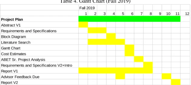
Table 4. Gantt Chart (Fall 2019)
Table 5. Gantt Chart (Winter 2020) Fall 2019
1 2 3 4 5 6 7 8 9 10 11 12
Project Plan
Abstract V1
Requirements and Specifications
Block Diagram
Literature Search
Gantt Chart
Cost Estimates
ABET Sr. Project Analysis
Requirements and Specifications V2+Intro Report V1
Advisor Feedback Due
Report V2
Winter 2020
1 2 3 4 5 6 7 8 9 10 11
Electrical Hardware
Design Actuator Driver Module, Purchase Components Assemble Actuator Driver Module
Test, Debug, and Revise Actuator Driver Module Design Power Supply, Purchase Components Assemble Power Supply
Test, Debug, and Revise Power Supply
Design Signal Processing Module, Purchase Components Assemble Signal Processing Module
Test, Debug, and Revise Signal Processing Module Assemble and Test All Electronics
Debug, Redesign If Necessary
Mechanical Hardware
Select Critical Components CAD Assembly, Purchase Parts Build Mechanical Structure Integrate and Test With Electronics Debug, Redesign If Necessary
Firmware
Digital Control Processing Debug
Whole Project Complete Documentation
Design Review
9
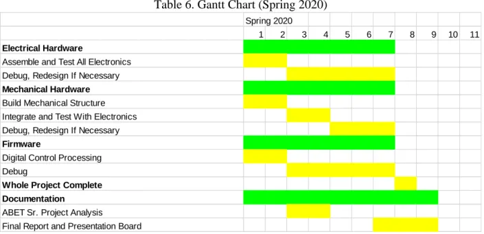
Table 6. Gantt Chart (Spring 2020)
Tables 4-6 above are the Gantt charts for each quarter of this project. Fall 2019 consists of planning and preparation tasks, which are complete as of the writing of this report. Winter 2020 will consist mostly of electronic design, assembly, and testing for the microcontroller, motor driver, and power supply. The mechanical design and construction of the frame and drive system will begin during this quarter, but at less of a priority than the electrical components. In Spring 2020, the electronics should be complete but additional time is allotted for
troubleshooting. The mechanical parts should be finished in the beginning of this quarter, and the mechanical and electronic systems will be integrated and tested together. The firmware will be finished in the beginning of the quarter and the whole system will undergo testing and
troubleshooting. The whole device should be functional by Week 7 of Spring quarter. The end of the quarter will consist of finishing the final report and the presentation board.
Cost Estimates
Table 7. Cost Estimates
Item Cost
(USD)
Explanations/Notes
Actuator 50 An upper average for medium sized gearmotors Electronic
Components
100 Microprocessor, ICs, passive components
PCB Manufacturing 40 For two boards plus shipping, multiple revisions Structural Materials 200 Aluminum extrusions and brackets
Fasteners 30 Moderate number of screws and nuts Mechanical
Components
100 Gears, shafts, bearings, etc.
Labor 2250 150 hours, $15/hour
Total 2770
Spring 2020
1 2 3 4 5 6 7 8 9 10 11
Electrical Hardware
Assemble and Test All Electronics Debug, Redesign If Necessary
Mechanical Hardware
Build Mechanical Structure Integrate and Test With Electronics Debug, Redesign If Necessary
Firmware
Digital Control Processing Debug
Whole Project Complete Documentation
ABET Sr. Project Analysis
10
Table 7 above enumerates the costs of the parts and materials needed to construct the solar tracker. The actuator is currently undetermined and may be a DC gearmotor, linear actuator, or brushless motor; $50 is allotted for the cost of this actuator since this is an average cost for medium sized motors. The electronics such as the microprocessor, power supply, and discrete components should total under $100, and the PCB manufacturing will likely be under $40 (This is a high estimate due to shipping and multiple revisions). Various mechanical parts are required such as aluminum extrusion for the frame, and gears, shafts, and bearings for the drive system. The project has approximately $1000 additional funding for aluminum extrusions and frame parts, but the actual cost of these parts will likely be well under this value,
approximately $200.
Chapter 2: System Design and Construction
2.1: Mechanical Structure
The experimental setup required a frame with appropriate dimensions and strength to carry a 2073x1072mm industry standard solar panel. The frame therefore must be 1m high from base to rotational axis ideally with 10-20cm additional clearance. The frame was composed mainly out of standard 3030 aluminum T-slot extrusion due to its strength and ease of
construction. Plates to attach the extrusion beams together were also bought off the shelf, and hardware to mount bearings were machined from aluminum. A 1/2 inch diameter steel D-shaft was the axis of rotation on which the panel would be mounted. The shaft was inserted through a pair of flange bearings mounted to aluminum plates, which were in turn mounted to the vertical frame T-slot extrusions. An ANSI 25 72 tooth sprocket was attached to the D-shaft. The
11
Figure 3: CAD Model of Extruded Aluminum Frame
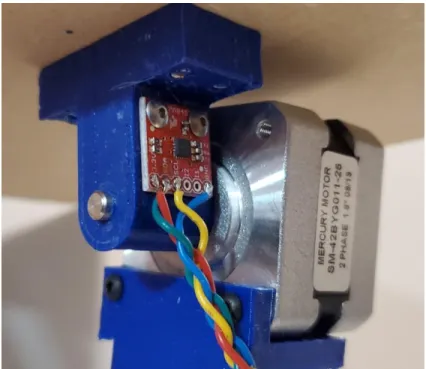
Due to circumstances preventing further work on the full size frame, a smaller prototype model was constructed in order to test the positional control system. The model did not require the structural strength or size to carry a solar panel. This version was constructed out of smaller 2020 size T-slot extrusions, 3/4 inch aluminum square tubing, and 3D printed brackets. A 3D printed hub connected an MDF board (to model the solar panel) and an accelerometer to the shaft of a stepper motor.
2.2: Stepper Motor and Motor Driver
12
of 24.9Nm. The geared motor torque far exceeds the torque required. While the gearing does improve the motor’s low speed capability, there is no minimum speed requirement for a stepper motor, which makes them ideal for low speed, high precision applications. The stepper motor has a 1.8 degree step angle, which when divided by the 100:1 gear ratio and the 14 to 72 tooth chain reduction, becomes 0.0035 degrees, which is an extreme level of precision for this application. A smaller step angle means the device can make smaller adjustments towards its target angle.
When the project shifted to a small scale model, torque was no longer a concern as the device did not need to carry the load of a real solar panel. A smaller, ungeared NEMA 17 stepper motor was chosen. The step angle of this stepper motor is 1.8 degrees according to the datasheet [14], which is inadequately precise for the purposes of a solar panel tracker. However, the step angle of a stepper motor can be divided into a higher resolution using microstepping, a control method that allows for divisions of the step angle by 2, 4, or 8 depending on the driver.
The stepper motor must be controlled using a stepper motor driver board. The requirements for the driver in this project were that it could run at 12V and that it had 1/8
microstepping. 12V is the standard motor voltage for solar panel trackers, as it allows the user to easily power the device using batteries. The microstepping requirement is so that the motor step angle can be subdivided into more precise steps. The selected stepper driver module was the Sparkfun Easydriver, which fulfills both of these criteria as per the specifications in the datasheet [15]. Given the 1.8 degree step angle of the motor, the stepper motor driver can divide the step angle by 8, for a microstep angle of 0.225 degrees. This allows for fine sub-degree adjustments.
The stepper motor driver board has two main control pins that take digital signals from the microcontroller: The DIR pin which determines which direction the motor rotates, and the STEP pin which tells the driver to make one step of the motor on the rising edge of the input signal. There is an additional ENABLE pin that can be used to turn the motor control on or off, and two pins (MS1 and MS2) that are used to select different subdivisions of microstepping. For the purposes of this project, the ENABLE pin was always set low to enable motor movement (this pin has active low logic), and both MS pins were set high to select 1/8 microstepping. The driver board has VCC and GND connections for the motor power, and four output pins to connect to the leads of a bipolar stepper motor. This setup is identical to the one detailed in the reference guide [16].
2.3: Accelerometer Angle Measurement
13
if the frame is not level with the true horizontal. Note that the accelerometer comes with
drawbacks, the most problematic being that the gravitational angle measurement is only accurate if the device is stationary and not accelerating, in which case the device cannot distinguish between these accelerations and gravitational acceleration.
The accelerometer used in this project was the MMA8452Q Triple Axis Accelerometer Breakout from Sparkfun. The MMA8452Q (detailed in the datasheet [17]) is a commonly used accelerometer IC, the breakout board includes supporting components and pads to connect to other devices. The device is well documented and this project utilizes libraries written by Sparkfun to easily read data from it as utilized in the reference guide [18]. The accelerometer is powered by a 3.3V source, and communicates with a microcontroller through I2C. It includes an SDA and SCL pin for the I2C data protocol. Due to the orientation the accelerometer is mounted to the motor output shaft, the Z axis is used as the measurement direction. To measure an angle, the accelerometer measures the current acceleration in Gs using the function “getCalculatedZ()” in the library. This returns a value that ranges from -1 to 1 given that there are no
non-gravitational accelerations. The measured angle is the inverse sine of this value. The control loop for this project measures and calculates this value each cycle in order to determine the current angle of the solar panel.
14 2.4: Microcontroller and Feedback Control
In order to utilize the libraries written for the accelerometer, the program was to be written in Arduino. The microcontroller must have connections for I2C to interface with the accelerometer, as well as a 3.3V power source. The microcontroller also requires five digital output pins to control the stepper motor driver. Processing requirements are fairly low, as the peripheral components are not dependent on high signal speeds, and the control loop runs at a low rate. For prototyping convenience, a small form factor board with breadboard compatible header pins was desirable. For these constraints, the Teensy 4.0 was chosen. It has the required data pins and is designed to be small and breadboard compatible. Its processing speed far exceeds that required for this project, but that is not a problem. Information about this microcontroller is detailed in the datasheet [19].
The Teensy 4.0 was replaced partway through the project with an Arduino UNO
microcontroller. This was due to a communication port problem with the host computer, which caused it to stop being compatible with the Teensy board. While an inconvenient deviation, it does confirm that the program has low processing requirements and is unaffected by the type of microcontroller used, provided that it has enough digital I/O pins and supports I2C.
The program first initializes the I/O and I2C pins, as well as the serial connection to the host computer. The stepper driver is enabled and set to 1/8 microstepping. The main loop begins, and the program prompts the user on the host computer to input a desired target angle value. Integer and float values are accepted, the program informs the user and re-prompts if the input is out of range (-90 to 90) or is a non-number. Once a valid setpoint is given, the secondary control loop begins, which begins with a calculation of the current angle using the accelerometer as detailed in section 2.3. The current angle is subtracted from the setpoint angle to find the error value, or how far the motor must turn to reach the setpoint angle. The error value is divided by 0.225 (the 1/8 microstep angle of the stepper motor) to find the number of motor steps required to reach the setpoint angle. The DIR pin on the stepper driver is set based on the sign of the error value, and the calculated number of pulses is sent to the STP pin of the motor driver to move the motor by the calculated position. In order to achieve higher accuracy, this loop is iterated
15
Chapter 3: System Performance
3.1: Performance Testing
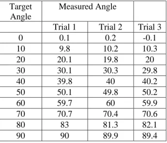
The primary performance metric was the device’s accuracy, in terms of positioning the solar panel as close as possible to the user input target angle. A series of tests was conducted to determine the accuracy of the device. The first experiment tests medium distance angle change intervals, stepping in increments of 10 degrees and measuring each position. This test was repeated three times.
Table 8. Medium Increment Positioning Test
Target Angle
Measured Angle
Trial 1 Trial 2 Trial 3
0 0.1 0.2 -0.1
10 9.8 10.2 10.3
20 20.1 19.8 20
30 30.1 30.3 29.8
40 39.8 40 40.2
50 50.1 49.8 50.2
60 59.7 60 59.9
70 70.7 70.4 70.6
80 83 81.3 82.1
90 90 89.9 89.4
The result of the medium increment test indicate that the device is capable of an accuracy of +/- 0.2 degrees from the target angle up until the 70 degree test. In the tests 70 degrees and after, the angle deviates multiple degrees from the target angle. In the 70 and 80 degree tests, the resulting angles are up to 3 degrees too high. Note that the 90 degree test remains at or below 90 degrees because the frame physically restrains it from moving past this angle. The
mathematically likely reason for this problem is that the angle calculation relies on taking the inverse sine of the acceleration. This means that as the panel becomes closer to vertical and the acceleration approaches 1, smaller changes in the input of the inverse sine function result in larger changes to the output. This causes the calculations to lose precision, especially given the limited number of digits produced by the accelerometer. While the device is technically capable of positioning from -90 to 90 degrees, the range for optimum accuracy is -70 to 70 degrees.
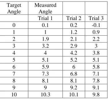
The second test measured the solar panel tracker’s ability to make small adjustments accurately. The test was run in the same manner as the medium distance test, except the angle was incremented by 1 degree for each data point. This test more accurately represents the solar panel tracker’s end use, as throughout the day a solar tracker only moves in very small
16
Table 9. Small Increment Positioning Test
Target Angle
Measured Angle
Trial 1 Trial 2 Trial 3
0 0.1 0.2 -0.1
1 1 1.2 0.9
2 1.9 2.1 2.2
3 3.2 2.9 3
4 4 4.2 3.8
5 5.1 5.2 5.1
6 5.9 6 5.8
7 7.3 6.8 7.1
8 8.1 8.1 7.8
9 9 9.2 9.1
10 10.3 10.1 9.8
The results of the small increment test show that the positional control is almost as accurate as the motor hardware allows when making small changes to the angle. The error is almost always up to +/- 0.2 degrees. These values are what were expected, given that the smallest adjustment the motor can make is 0.225 degrees. This means the device is incapable of adjustments smaller than 0.225 degrees. It is likely that a geared stepper motor or one built with smaller steps would be able to achieve higher accuracy.
3.2: Expense Tracking
Table 10 below enumerates the costs of the hardware components purchased for the development and construction of the project. The hardware cost ($271.42) was far below the initial estimated cost of $520. The initial calculations slightly overestimated the cost of the mechanical and structural components. The cost of the motor and electronics were further overestimated, the main difference being that the original estimate anticipated PCB manufacturing and higher power
17
Table 10. Expenses (Actual)
Item Cost (USD) Quantity Extended Cost (USD)
½ Inch Diameter D-Shaft, 36 Inch 24.62 1 24.62 ANSI 25 Roller Chain Sprocket, 14T 11.54 1 11.54 ANSI 25 Roller Chain Sprocket, 72T 45.08 1 45.08 ANSI 25 Roller Chain, 3 Feet 15.42 1 15.42
ANSI 25 Roller Chain Link 1.00 1 1.00
½ Inch Set Screw Shaft Collar 1.68 2 3.36
½ Inch Flange Bearing 7.30 2 14.60
M5x10 Screws, 100 Pack 5.95 1 5.95
M5 Hammer Nuts, 100 Pack 13.95 1 13.95
3030 90 Degree T Joining Plate 2.45 4 9.80
3030 90 Degree Bracket 3.45 4 13.8
3030 Aluminum Extrusion, 2000mm 16.95 2 33.90
Teensy 4.0 19.95 1 19.95
Breadboard 9.95 1 9.95
XT60 Connector 1.50 1 1.50
Jumper Wires M/M 2.25 1 2.25
Jumper Wires M/F 1.95 1 1.95
Jumper Wires F/F 1.95 1 1.95
Stepper Motor 15.95 1 15.95
EasyDriver Stepper Motor Driver 14.95 1 14.95 Sparkfun Accelerometer Breakout 9.95 1 9.95
18
Chapter 4: Conclusion
4.1: Accomplishments
The final version of the device mostly fulfilled the purpose of the project. Many
mechanical goals of the project such as carrying capability had to be completely abandoned, as the full size prototype could not be constructed and a smaller model was substituted. Regarding the engineering specifications, the model fulfilled the requirements for speed, movement range, and accepting inputs from an external computer. Water/dust ratings, power consumption, and carrying capacity became non-issues. While it was not an original numerical engineering
specification, accuracy became a main focus for the device. The model offers accuracy within +/- 0.2 degrees, which is considered to be accurate enough for solar panel trackers. The method of positional control utilized for this project, while needing some improvements, has potential as a low cost and low computing power method for controlling solar panel trackers at low speeds and high precision.
4.2: Improvement Opportunities
The accuracy of the device’s positional control would benefit greatly from using a geared stepper motor. Gearing down the stepper motor would effectively divide the step angle further, allowing for adjustments of very small fractions of a degree. In addition, the gearing would reduce the vibration of the panel, reducing the necessary pause time between control loop
19
References
[1] R. Ford and C. Coulston, Design for Electrical and Computer Engineers, McGraw-Hill, 2007, p. 37
[2] IEEE Std 1233, 1998 Edition, p. 4 (10/36), DOI: 10.1109/IEEESTD.1998.88826
[3] Shin, H. (2019). Altitude and azimuth angle concurrent driving type solar tracking apparatus. 10,404,207.
[4] Judkins, Z. (2019). Photovoltaic assembly for use in diffuse weather conditions and related methods. 10,415,974.
[5] Sumathi, Vijayan, et al. “Solar Tracking Methods to Maximize PV System Output – A Review of the Methods Adopted in Recent Decade.” Renewable and Sustainable Energy Reviews, vol. 74, pp. 130–138, July 2017.
[6] Sunpower Corporation (Author Unknown), Sunpower E-Series Commercial Solar Panels | E20-435-COM, Sept. 2017.
[7] Yao, Yingxue, et al. “A Multipurpose Dual-Axis Solar Tracker with Two Tracking Strategies.” Renewable Energy, vol. 72, pp. 88–98, Dec. 2014.
[8] Mendoza, J. M., et al. “Analytical Synthesis for Four-Bar Mechanisms Used in a Pseudo-Equatorial Solar Tracker.” Ingenieria E Investigacion, vol. 33, no. 3, pp. 55–60, Dec. 2013.
[9] Tatu, I.N., et al. Designing and Optimizing the Control System of the Tracking Mechanism for a String of Photovoltaic Modules. WIP, 2011.
[10] L. Ngan, C. Jepson, A. Blekicki and A. Panchula, "Increased energy production of First Solar horizontal single-axis tracking PV systems without backtracking," 2013 IEEE 39th Photovoltaic Specialists Conference (PVSC), Tampa, FL, 2013, pp. 0792-0796.
[11] Y. M. Safan, S. Shaaban and M. I. A. El-Sebah, "Hybrid control of a solar tracking system using SUI-PID controller," 2017 Sensors Networks Smart and Emerging Technologies (SENSET), Beirut, 2017, pp. 1-4.
doi: 10.1109/SENSET.2017.8125035
[12] Oh, Seung Jin, et al. “Development of an Embedded Solar Tracker for the Enhancement of Solar Energy Utilization.” International Journal of Energy Research, vol. 36, no. 2, pp. 249–258, 2012.
[13] “Stepper Motor 23HS22-2804S-HG100,” 20-Aug-2018. [Online]. Available:
https://www.robotshop.com/media/files/content/o/omc/pdf/nema-23-stepper-motor-bipolar-1001-high-precision-planetary-gearbox-schematic.pdf.
[14] XUHEZHAO, “SM-42BYG011-25,” 27-Mar-2009. [Online]. Available:
https://www.sparkfun.com/datasheets/Robotics/SM-42BYG011-25.pdf.
20 [16] Easy Driver Hook-up Guide. [Online]. Available: https://learn.sparkfun.com/tutorials/easy-driver-hook-up-guide?_ga=2.221236888.1000626501.1591645684-2138174839.1581799593. [Accessed: 09-Jun-2020].
[17] “Xtrinsic MMA8452Q 3-Axis, 12-bit/8-bit Digital Accelerometer,” Oct-2013. [Online]. Available: https://cdn.sparkfun.com/datasheets/Sensors/Accelerometers/MMA8452Q-rev8.1.pdf.
[18] MMA8452Q Accelerometer Breakout Hookup Guide. [Online]. Available:
https://learn.sparkfun.com/tutorials/mma8452q-accelerometer-breakout-hookup-guide?_ga=2.228574109.1000626501.1591645684-2138174839.1581799593. [Accessed: 09-Jun-2020].
21
Appendices
Appendix A. Source Code
//Code for stepper motor and accelerometer based positional control for solar panel tracker
//Ezra Pramono //June 9, 2020
#include <Wire.h> // Must include Wire library for I2C
#include "SparkFun_MMA8452Q.h" // Click here to get the library:
http://librarymanager/All#SparkFun_MMA8452Q
#include <math.h>
MMA8452Q accel; // create instance of the MMA8452 class
//Declare pin functions on Microcontroller
#define stp 2 #define dir 3 #define MS1 4 #define MS2 5 #define EN 6
//Declare variables for functions
int x;
char inputBuffer[16];
float setpoint;
float acceleration;
float currentAngle;
float error;
int stepCount;
int cycles;
void setup() {
pinMode(stp, OUTPUT);
pinMode(dir, OUTPUT);
pinMode(MS1, OUTPUT);
pinMode(MS2, OUTPUT);
pinMode(EN, OUTPUT);
Serial.begin(9600); //Open Serial connection for debugging Serial.println("Enter Angle in Range -90 to 90");
Wire.begin();
if (accel.begin() == false) {
Serial.println("Not Connected. Please check connections and read the
hookup guide.");
while (1);
}
digitalWrite(MS1, HIGH); //Pull MS1, and MS2 high to set logic to 1/8th microstep resolution
22
digitalWrite(EN, LOW); //Pull enable pin low to allow motor control
}
void loop() {
// put your main code here, to run repeatedly:
while(Serial.available()){
Serial.readBytes(inputBuffer, sizeof(inputBuffer)); //read serial input, convert to numerical value
float userInput = atoi(inputBuffer);
memset(inputBuffer, 0, sizeof(inputBuffer));
error = 1; //initialize reference value to avoid an error in loop later cycles = 0;
if (userInput <= 90 && userInput >= -90) { //make sure input is within bounds
setpoint = userInput; //record input as setpoint
Serial.print("setpoint ");
Serial.println(setpoint);
while ((error > 0.25 or error < -0.25) && cycles < 10) { //loop until adequately close to setpoint or reaches 10 cycles
acceleration = accel.getCalculatedZ(); //read Z axis acceleration from accelerometer
if (acceleration < -1) { //Avoid inverse cosine error acceleration = -1;
}
else if (acceleration > 1) {
acceleration = 1;
}
Serial.print("acceleration ");
Serial.println(acceleration);
currentAngle = asin(acceleration)*57.2958; //take inverse sine of acceleration, convert from radians to degrees
Serial.print("current angle ");
Serial.println(currentAngle);
error = setpoint-currentAngle; //find error value from current angle to setpoint
Serial.print("error ");
Serial.println(error);
Serial.println();
stepCount = abs(error)/0.225; //calculate number of steps required to reach setpoint
if (error > 0) {
digitalWrite(dir, HIGH); //Pull direction pin low to move counterclockwise (towards positive angle)
}
else if (error < 0) {
23
}
for(x= 0; x<stepCount; x++) //send pulses equal to stepCount {
digitalWrite(stp,HIGH); //Trigger one step delay(5);
digitalWrite(stp,LOW); //Pull step pin low so it can be triggered again
delay(5);
}
cycles += 1;
delay(1000);
}
Serial.println("Finished");
}
else {
Serial.println("Input out of bounds");
}
} }
Appendix B. ABET Senior Project Analysis
• 1. Summary of Functional Requirements
Optimal solar panel systems rotate to track the sun, as solar panels operate at their maximum potential when the panel plane is completely normal to the sun’s rays. These tracking systems often using two axes of movement. This project is to design a system that will allow a solar panel to track the sun using only one rotational axis, which saves energy and uses fewer parts. The system tracks the entire range of the sun's motion and has positional feedback to allow control of the solar panel's angle. The position of the tracking system is controllable via an external computer. The goal of this project is to construct a solar tracking device that accurately tracks the sun in order to maximize the energy output of the solar panel.
• 2. Primary Constraints
The tracking module would ideally have a -90° to 90° range of movement in order to track the sun’s full range of movement throughout the day. Also, tracking the sun, by definition, requires that the device rotates the solar panel fast enough to keep up with the sun’s movement. Since this project does not encompass the control system and tracking algorithm, it must be able to communicate with an external device to control its movement. While the goal of the project is to create a tracking system that consumes as little power as possible, there should be a benchmark of 10% relative to the solar panel’s maximum power output. For the tracker to achieve a net gain in power output, its power consumption must be small compared to the increase in efficiency it causes.
• 3. Economic
24 People may invest in this product in the hopes of making a return on the increase in solar power output they provide. In addition, the device improves the energy output of solar panels, allowing solar farms to generate more profit. The implementation of this product would increase the yield of a solar energy plant, thus producing more profit for the user and making solar power more desirable. The device is likely to reduce the use of fossil fuels, as it would cause an increase in solar energy yield by approximately 25-30%. The project earns money for the manufacturer and investors dependent on how many units are sold, and earns money for the end user by increasing the yield of solar power production.
Costs accrue through the project’s lifecycle as the device requires repairs and maintenance. This includes parts and materials as well as human labor costs to maintain and fix the devices. The mechanical parts are relatively standard and most are off-the-shelf, which should make replacement and maintenance
economical. The electronics consist of several off-the-shelf modules, which makes it simple to swap out parts. Benefits accrue as the device increases solar panel module output. By improving solar module efficiency, the product increases the total energy yield of solar farms over time.
The estimated cost of the project is $2770 (See Cost Analysis, page 8), which includes electronic parts, structural and mechanical materials, and human labor. In addition to consumables, the project also requires the use of electrical and mechanical shop tools and equipment. This includes oscilloscopes, power supplies, and soldering tools used to test and assemble electronic systems, as well as the cutting and machining tools used to construct mechanical components and the frame. The true cost was $2521.42, due to the electronics being simplified and less expensive than anticipated in the original plans. However, this change was partly due to the downscaling of the final product to a miniature model.
• 4. If manufactured on a commercial basis:
The cost of hardware was $271.42. This cost could be brought down to $200 if the materials are bought wholesale in bulk, and the electronics production is optimized. Manufacturing labor is estimated to be approximately $150, assuming $15/hour wages and 10 hours of assembly per product. The manufacturing cost is estimated to be about $350. An estimated 10000 units are to be sold each year, depending on the capacity of the manufacturer. If the sale price is $600 for a profit of $250, the estimated annual profit is $2.5 million.
The cost for the end user to operate the device is dependent almost entirely on repair and maintenance. For the purpose of this calculation, the required maintenance is regular lubrication and inspection, and occasional repair of wiring and replacement of gears, sprockets or bearings. If inspection and lubrication labor costs $20 per hour and is half an hour per device per month, and an annual gearbox replacement is $50, the annual maintenance cost is $570.
• 5. Environmental
The environmental impact of this project is mostly positive, as it increases solar power yield by
25
• 6. Manufacturability
The manufacturing supply chain requires the use of off-the-shelf components, and the supply of these products may become unstable. This is an issue that would be resolved with planning and inventory management. The electronics would ideally be consolidated into a single board, which simplifies
manufacturing since there are fewer boards to produce. The electronics are mostly surface mount ICs and passive components, with some through-hole mounts for connectors and larger components. All the electronics can be produced using standard existing PCB technologies. Since the physical structure is constructed out of bolted together extrusions and brackets, manufacturing consists of the production of these base components and their assembly. Most of the base components such as the aluminum extrusion would be bought from a third party supplier, only requiring custom manufacturing for motor mounts, bearing blocks, and other items unique to this product. Assembly would be very simple, as there is no welding or other expensive processes that need to be done.
• 7. Sustainability
When the system requires repairs and maintenance, the solar module under repair will be out of commission, decreasing energy yield and disrupting the power flow of the plant. However, due to the mostly off-the-shelf components, replacement parts are easy to find, and since the electronics are mostly modular, it would be easy to swap out individual modules. Maintaining this device will likely require the replacement of electronic components. Ideally, damaged electronic components are to be recycled, but E-waste infrastructure is not always available. The parts most likely to incur wear are the stepper motor, gears, and bearings. Recycling for gears and other mechanical components is already commonplace. Motors must go to E-waste, but consist of copper windings and magnets that are easily separated and recycled. Adding a second axis of tracking would increase yield further, but has other drawbacks such as increasing space required and drawing more energy to power itself. Adding a second axis would also double many of the current parts required: a second motor, accelerometer, and motor driver.
• 8. Ethical
The main IEEE ethical code this project fulfills is “1) to hold paramount the safety, health, and welfare of the public, to strive to comply with ethical design and sustainable development practices, and to disclose promptly factors that might endanger the public or the environment;”
The use of the product is ethical as it promotes the use of renewable energy. This benefits the safety and welfare of the public through its benefits for the environment. The product strives to comply with sustainable design practices by increasing the use of solar energy in opposition to nonrenewable energy sources.
The product also fulfills the ethical code “5) to improve the understanding by individuals and society of the capabilities and societal implications of conventional and emerging technologies, including intelligent systems; “
The intention of the project is to clearly state how the product will affect humanity in the ecological and economic manners outlined in previous sections. A large effort will be made to publicize all projected effects on the environment and on jobs and investment, both positive and negative.
The project must also fulfill the ethical code “3) to be honest and realistic in stating claims or estimates based on available data; “
26
• 9. Health and Safety
The manufacturing and maintenance of this product may be an inherent danger due to the tools and processes required. For example, the product has moving parts such as the actuator that may be a pinch hazard to the operator. The device moves a large and heavy solar panel that presents a collision hazard. Precautions must be taken in order to produce and maintain the devices safely. While the voltages and currents used in the product are relatively low, they still pose a potential electrocution hazard to those operating it or performing maintenance. Basic electrical safety measures, such as ensuring power is off before handling, must be followed by the operators of this device.
• 10. Social and Political
If this project succeeds in making solar power more productive and more desirable, energy companies will invest less in fossil fuels in favor of solar energy. This may lead to backlash from parties supporting the interests of fossil fuel production. Such a decline in fossil fuel usage would threaten the jobs and livelihoods of those working in the fossil fuel industry, which includes many low and middle class workers. In addition, there would be inequities among companies planning to utilize the product. Since implementing solar tracking on a large scale requires substantial overhead, struggling solar companies would be at a disadvantage against the ones that can afford to install the system.
• 11. Development