[Prasad, 6(7): July 2019] ISSN 2348 – 8034 DOI- 10.5281/zenodo.3345194 Impact Factor- 5.070
(C)Global Journal Of Engineering Science And Researches 31
G
LOBAL
J
OURNAL OF
E
NGINEERING
S
CIENCE AND
R
ESEARCHES
ANALYSIS AND DESIGN OF MULTISTORY BUILDING WITH GRID SLAB USING
ETABS
B. Syam Prasad*1 & B. Syam2
*1M. Tech Scholar, Department of Civil Engineering, ST. Mary’s Group of Institutions Guntur, Andhra Pradesh, India
2Asst Professor, Department of Civil Engineering, ST. Mary’s Group of Institutions Guntur, Andhra Pradesh, India
ABSTRACT
Grid floor structures along with beams spaced at regular intervals in perpendicular directions, monolithic with slab. They are usually hired for architectural reasons for big rooms inclusive of auditoriums, vestibules, theatre halls, display rooms of shops wherein column loose area is regularly the primary requirement. In the present study, “Analysis and Design of Multistory Building with Grid Slab Using ETABS” is carried out parameter like quantity of concrete, quantity of steel, bending moment, shear force and displacement of grid slab system is consider. In this present study, slab system design and analysis for G+5 building for seismic zone III and having medium soil condition by using E-Tabs. The analysis and design of slab system is done as per IS 456-2000 and IS 1983-2002.
Keywords: Grid floor, ETABS, wind and earth quake.
I. INTRODUCTION
Grid slab systems are being commonly used or supporting building floors bridge decks and overhead water tanks slabs. A grid is a planar structural system composed of continuous members that either intersect or cross each other. Grids are used to cover large column free areas and have been constructed in number of areas in India and abroad. Is subjected to loads applied normally to its plane, the structure is referred as Grid. It is composed of continuous member that either intersect or cross each other. Grids in addition to their aesthetically pleasing appearance provide a number of advantages over the other types of roofing systems.
Grid slab is divided into 3 types 1. Rectangular grid 2. Skewed Grids
[Prasad, 6(7): July 2019] ISSN 2348 – 8034 DOI- 10.5281/zenodo.3345194 Impact Factor- 5.070
(C)Global Journal Of Engineering Science And Researches 32
3. Curved surface Grids 4. Advantages of Grid slabs: Uses of Grid slabs
Grids are very efficient in transferring concentrated loads and in having the entire structure participate in the load carrying action.
Reduce the depth to span ration of rectangular grids.
Reduction in depth, towers, structural and other cost by reducing the height of the building
Used in the areas where number of columns are provided i.e., it is basically used in the areas which has huge spans.
Used for specialized projects that involves clean rooms, spaces requiring seclusion from low frequency vibration or those needing low floor deflections.
The concrete grid slab is often used for industrial and commercial buildings while wood and metal waffle slabs are used in many other construction sites.
This form of construction is used in airports, parking garages, commercial and industrial buildings, residences and other structure requiring extra stability.
The main purpose of employing this technology is for its strong foundation characteristics of crack and sagging resistance. Grid slab also holds a greater amount of load compared with conventional concrete slabs.
Shrinkage of slab is lower than stiffened rafts and footing slabs. They used 30% less concrete than a stiffened raft.
They use 20% less steel than a stiffened raft. II. LITERATURE REVIEW
Chintha Santhosh, Venkatesh Wadki, S.Madan Mohan, S.Sreenatha Reddy were presents Grid floor systems consisting of beams spaced at regular intervals in perpendicular directions, monolithic with slab. They are generally employed for architectural reasons for large rooms such as auditoriums, vestibules, theatre halls, show rooms of shops where column free space is often the main requirement. The rectangular or square void formed in the ceiling is advantageously utilized for concealed architectural lighting.
S. A. Halkude, C. G. Konapure and S. P. Pasnur are investigating various parameters involved, a solution for optimum structural configuration can be found for the grid floor. The present work includes the parametric investigation in terms of flexural actions such as bending moments and shear force. Spacing of grid beam is one of the important parameters considered for investigations, along with depth of grid beam & depth of periphery beam. Stiffness method is used for analysis which is less time consuming as compare to other analysis methods, where spacing of grid beams i.e. (l/b) is varied for hall size (L/B) with constant ratio. Here the depths of periphery beams (PB) are varied, for considered depth of periphery beams; various depths of grid beams (GB) are varied to arrive at optimum solution.
Coronelli, Dario was presented the grid model is proposed for the nonlinear behavior of Grid-slab structures. The inelastic response of the structure is concentrated in point hinges introduced into beam finite elements, modeling the response in bending, torsion, and shear. Both concentric punching and failures with unbalanced moments and shear are investigated. Static pushover analysis is used for the effects of gravity and lateral loads. The results are compared to experimental studies on interior, lateral and corner slab-column connections. The effect of different types and arrangements of transverse reinforcement and the influence of the gravity load level on the drift capacity are shown.
Methods of analysis of structure in ETABS:
The seismic analysis should be carried out for the buildings that have lack of resistance to earthquake forces. Seismic analysis will consider dynamic effects hence the exact analysis sometimes become complex. However for simple regular structures equivalent linear static analysis is sufficient one. This type of analysis will be carried out
[Prasad, 6(7): July 2019] ISSN 2348 – 8034 DOI- 10.5281/zenodo.3345194 Impact Factor- 5.070
(C)Global Journal Of Engineering Science And Researches 33
for regular and low rise buildings and this method will give good results for this type of buildings. So in this analysis we are using Equivalent linear static analysis.
III. MODELING OF R.C MOMENT RESISTING FRAME
In this present study G +4 storey building is considered 22.86 m x 18.29 m size which is 3 x 3 bays of 7.62 m (25 feet = 300 Inch) in x-direction and 6.096 (20 Feet = 240 Inch) in y-direction along the bay. The modeling is done in ETABS 2016. The structure is divided into frame and shell elements. Grid lines are made for the x, y and z direction
[Prasad, 6(7): July 2019] ISSN 2348 – 8034 DOI- 10.5281/zenodo.3345194 Impact Factor- 5.070
(C)Global Journal Of Engineering Science And Researches 34
3.1 Specification of Structure
3.2. Loading Condition
The loads considered during design and analysis of multistoried building is as follows 1. Dead load: It is taken as according to IS -875 (Part 1): 1987
Dead load = Density of concrete x Slab thickness = 25kn/m3 x 0.125m = 3.125kn/m2
b) Masonry load on plate = 1kn/m2 c) Floor finishing = 1.5kn/m2
2. Live Load: It is calculated as per IS-875 (part 2):1987 Live load on floors = 2 kn/m2
Total weight of slab =7.625kn/m2
3. Earthquake load: It is calculated as per IS-1893 (part 1): 2002 Seismic Definition
Earthquake zone – III (Z=0.16) Response reduction factor – 5 Importance Factor – 1.5 (Very Important Building) Rock and Soil Site Factor-1 (Medium Soil Building)
Type of Structure- 1 Damping - 5% (0.05) Soil Type: Medium soil
[Prasad, 6(7): July 2019] ISSN 2348 – 8034 DOI- 10.5281/zenodo.3345194 Impact Factor- 5.070
(C)Global Journal Of Engineering Science And Researches 35
[Prasad, 6(7): July 2019] ISSN 2348 – 8034 DOI- 10.5281/zenodo.3345194 Impact Factor- 5.070
(C)Global Journal Of Engineering Science And Researches 36
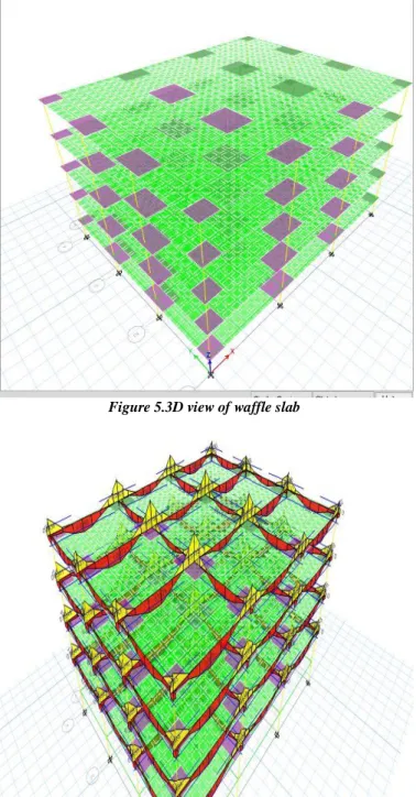
Figure 5.3D view of waffle slab
[Prasad, 6(7): July 2019] ISSN 2348 – 8034 DOI- 10.5281/zenodo.3345194 Impact Factor- 5.070
(C)Global Journal Of Engineering Science And Researches 37
Figure 7. Waffle slab Detailing
[Prasad, 6(7): July 2019] ISSN 2348 – 8034 DOI- 10.5281/zenodo.3345194 Impact Factor- 5.070
(C)Global Journal Of Engineering Science And Researches 38
IV. EXPERIMENTAL RESULTS
The following are the graphs derived from waffle slab analysis
Maximum Story Displacement: Story drift is the difference of displacements between two consecutive stories divided by the height of that story. Story displacement is the absolute value of displacement of the storey under action of the lateral forces.
Figure 9. Showing the Maximum story Displacement in EQ-X direction in EQ –Y direction
1) Storey shear: It is the lateral force acting on a storey due to the forces such as seismic and wind force. It is calculated for each storey, changes from minimum at the top to maximum at the bottom of the building.
[Prasad, 6(7): July 2019] ISSN 2348 – 8034 DOI- 10.5281/zenodo.3345194 Impact Factor- 5.070
(C)Global Journal Of Engineering Science And Researches 39
Figure 10. Showing the story shear in EQ-X direction in EQ –Y direction
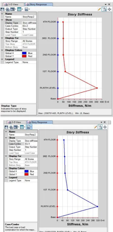
2) Storey stiffness : stiffness is the extent to which an object resists deformation in response to an applied force.The complementary concept is flexibility or pliability: the more flexible an object is, the less stiff it is.
[Prasad, 6(7): July 2019] ISSN 2348 – 8034 DOI- 10.5281/zenodo.3345194 Impact Factor- 5.070
(C)Global Journal Of Engineering Science And Researches 40
3)
Figure 11. Showing the story shear in EQ-X direction in EQ –Y direction
V. CONCLUSSIONS
In this present work ETABS is used to analysis the waffle slab structure of G+4 considering the gravity and lateral loads. The following conclusion is drawn from present work.
[Prasad, 6(7): July 2019] ISSN 2348 – 8034 DOI- 10.5281/zenodo.3345194 Impact Factor- 5.070
(C)Global Journal Of Engineering Science And Researches 41
1) The quantity of concrete required for grid slab multi story building is maximum and for other slabs is less. 2) It is also seen that the quantity of concrete is increase with increase span / grid size of the structure for the
same slab system. The quantity of concrete is least for smaller span of the structure and it is most for larger span of the structure.
3) The center-to-center spacing between ribs is found to be (6.57%-14.76%) of the span length to get the optimum total cost of waffle slab with solid heads, while it should be (8.22%-16.23%) of the span length for optimum design of waffle
4) The increasing in the ratio of concrete cost relative to the steel cost causes a decreasing in the rib spacing and the cross-sectional area of the ribs. While the increasing in the steel unit cost relative to the concrete unit cost causes an increasing in the cross-sectional area of the ribs.
5) .Maximum axial force in the structure is 22031.36 KN 6) Maximum tensile force is 7350.726 kN.
7) Maximum diaphragm drift is 0.007400. 8) Design of R.C.C slab 100 mm thickness
9) Storey drift values of different types of buildings are within the permissible limit as per IS-1893-2002 code provision
REFERENCES
1. IS: 875-1987. ‘Indian Standard Code of Practice for Design Loads (other than Earthquakes) for Buildings and Structures, (2nd revision).’ Bureau of Indian Standard, New Delhi
2. IS: 456-2000. ‘Indian Standard Code of Practice for Design of reinforced concrete”, Bureau of Indian Standard, New Delhi
3. Design of Reinforced concrete structures by S. Ramamrutham and R. Narayanan, 17 th edition Dhanpat Rai Publishing Company.
4. A Sathawane R.S Deotale 'Analysis and design of flat and grid slab and their comparision, international journal of engineering Research and their applications vol 1. Issue.3.PP 837-848.
5. Baishali Das Static and dynamic analysis of grid beams, project report of Bachelor of technology, Deportment of civil engineering, National institute of technology Rourkila