Virtual Cockpit: An Alternative
Augmented Reality User Interface
Alexander Terbu
∗Institute for Computer Graphics and Vision
Inffeldgasse 16/II
A-8010 Graz / Austria
Abstract
This paper presents an approach for a hierarchical graphi-cal user interface in an Augmented Reality environment, which allows fast and intuitive navigation even when dealing with complex layouts. This project enhances the “Studierstube” library by providing a head-fixed 3-dimensional menu hierarchy as an alternative to the per-sonal interaction panel. Although providing a natural hap-tic feedback we have experienced different limitations in terms of usability and flexibility by using this personal interaction panel for application control and navigation. This paper shows a concept work for a different user in-terface called Virtual Cockpit providing a complete 3-dimensional experience. Moreover, a methodology for dealing with complex interaction layouts by introducing a smart tree structure is also discussed.
Keywords: augmented reality, user interface
1
Introduction
Augmented Reality (AR) is a very powerful and flexible technology by superimposing the real world with virtual objects. The reality can therefore be enriched with addi-tional content and information used for different applica-tions [1]. In recent years some research groups have devel-oped frameworks providing a library for AR-based appli-cations [15] [11] [4]. One of these systems is the “Studier-stube” project which is capable of rendering, tracking, teraction handling and user collaboration [15]. User in-teraction is done by using two tracked input devices, first the so-called personal interaction panel (PIP) and second a pencil (PEN) optionally with some mounted buttons [17]. Approaches using panels like the PIP benefit from passive haptic feedback which is an advantage for an AR system.
However, that interaction between PEN and PIP heavily depends on an accurate calibration of the whole AR sys-tem. However, a well calibrated system is not often the case because calibration of such systems is mostly a hard and tedious task. This often leads to tracking artifacts. For instance, if selecting buttons or sliders on the PIP a
selec-∗[email protected]
tion event may be triggered, although the PEN is next to the widget.
The Virtual Cockpit approach does not rely on a well-calibrated system, but provides a 3D user interface without using the PIP. This idea is based upon three important is-sues. First, it provides a smart hierarchical menu structure, which allows a fast selection of hierarchical grouped inter-action buttons. Second, our auto enlargeable and therefore easy selectable 3D widgets provide a very flexible way of application control and navigation. In addition, our Vir-tual Cockpit leads to an enhanced reduction of physical ex-haustion in long-term sessions by not using the PIP. Third, by being head-fixed and hideable, the user has never an unnecessarily obstructed view to the scene.
The crucial factor for starting our project was the lack of very mobile solutions aside from approaches using fly-ing menus [8] or 3D-Desktop-Managers [14]. The Virtual Cockpit provides an alternative which is able to force effi-cient and easy work in AR, particularly when used in con-junction with smaller panels. We chose the name Virtual Cockpit, because the control center is always available in front of the user and provides a true 3D user interface.
The rest of this paper is organized as follows. At first we discuss related work in this field, which influenced our de-sign. In the second part we present the idea and design of the Virtual Cockpit and describe typical use cases. Subse-quent to that, we show the integration into the “Studier-stube” library and finally we give an outlook to future work.
2
Related Work
In 1999 Serra et al. developed an interface for precise work with volumetric datasets [7]. Their focus lied on reducing physical exhaustion by using a static real panel. The track-ing artifacts by an inaccurate calibration were reduced us-ing this panel approach. In addition they used a scrollable virtual panel, with free definable and direct selectable ar-eas of interest. Hence they offered theoretically unlim-ited extensibility, whereas the used solution was limunlim-ited in terms of efficient navigation and a good overview due to either rapid changes of the current layout or the need for extensive scrolling. Moreover they used 2.5D widgets,
which are not always easy to select even without tracking artifacts. Positive influence to our work had the fact that their panel was only visible when the pen was close. As a result it never unnecessarily obstructed the users view.
Deering worked on a mixture between 2D and 3D wid-gets organized in a disk layout [6]. The disk was aligned in parallel to the view plane, and was used in conjunction with a 3-button, 6-degrees of freedom (DOF) wand held in the hand. When invoked, the menu popped up relative to the current position of the tip of the wand. Similarly, Sowizral [16] and Wloka et al. [19] used pop-up menus that showed up in the same location relative to a 6-DOF mouse. In addition they used the mouse buttons to cycle through menu entries.
Many approaches tried to transport the desktop-metaphor to 3D by using 2.5D widgets. Although it gives a user the confident feeling known from the desktop, it oth-erwise also increases the mentioned selection problems as the result of using small widgets when dealing with com-plex user interfaces.
Jacoby et al. designed a hierarchical menu structure with pop-up and pull-down menus and employed a cou-ple of different hand gestures for selecting the menu items [10]. Another approach for menu selection was done by Ferneau et al. [9]. They used a 3D widget as a virtual in-strument provided with menu items and had a 3D mouse as their primary interaction device, where the buttons of this 3D mouse were connected to the items of the virtual in-strument. The drawback is that the abilities of the physical device had to match those of the virtual. Feiner et al. used 2D windows for a 3D AR environment [8]. They displayed a transparent window relative to the user’s head. Their sys-tem distinguished between three kinds of windows. First, display-fixed windows displayed at fixed positions relative to the user’s head. Second, they discuss about surround-fixed windows displayed at a surround-fixed position in the world coordinate system. Third, they used world-fixed windows, constrained to locations or objects. The main disadvantage was that they were still using flat windows, but supported by a display-fixed approach.
While most virtual menus were usually implemented as a 2.5D object, Liang et al. developed a 3D modeling system and introduced the 3D object menu concept [12]. They had a 3D ring menu which used also 3D objects in-stead of 2.5D ones and was easy to use. A similar ap-proach was done by Dachselt, who picked up the idea of Toolspaces [13] and used real 3D widgets, to avoid discon-tinuities between 2D and 3D [5]. This was an approach to make navigation in feature-rich applications clearer and easier due to the use of well defined hotspots (Action-Spaces) with disk like aligned tool palettes.
A different way of virtual menu based systems, based on the ”pen and panel” metaphor are presented in [17] [3]. In this context Szalavari et al. introduced the known PIP for the “Studierstube” [17]. Although we cannot dis-miss known benefits of ”pen and panel” approaches like passive haptic feedback, we have experienced some
draw-backs. On the one hand the mentioned tracking artifacts are revealed, whereas on the other hand the interaction is limited to the physical size of the panel. The only alter-native for complex user interfaces is to use more of the PIP’s sheets or increase the PIP’s size. A sheet is one par-ticular representation of a panel with all its widgets and the PIP allows to switch between them during application. Both ways would result again in a non concise view and in terms of size in additional physical strain, which is es-pecially true for complex user interfaces. In this case we think it lacks of practicability. Furthermore the PIP is usu-ally based on 2.5D widgets, suffering from the discussed selection problems. This was one of the main reasons to introduce the Virtual Cockpit.
In our approach, we overcome the drawbacks in terms of selection by using real 3D menus with enlargeable wid-gets, which are head-fixed aligned on a plane. This allows easy selecting and eliminates influence of the tracking ar-tifacts. Due to the enlargeable widgets and the head-fixed user interface alignment a precise calibration is not neces-sarily required. Moreover our approach supports a hierar-chical menu structure for a practicable and fast navigable representation of large and complex user interfaces.
3
Methods
3.1
Motivation and Design
Our primary user interfaces so far used are the PIP and PEN of the “Studierstube”. However, the more our ap-plications evolved over time the more user interface func-tionality was demanded. This was especially true for our “Liver Surgery Planning System” [2]. For example taking and analyzing several snapshots of objects and organizing them on the user interface. But this was going to hit the mentioned limits of the currently used PIP. However, our way should ensure a coexistence between a 3D user inter-face and the PIP, to combine the best of both.
3.1.1 Introduction to Main Components
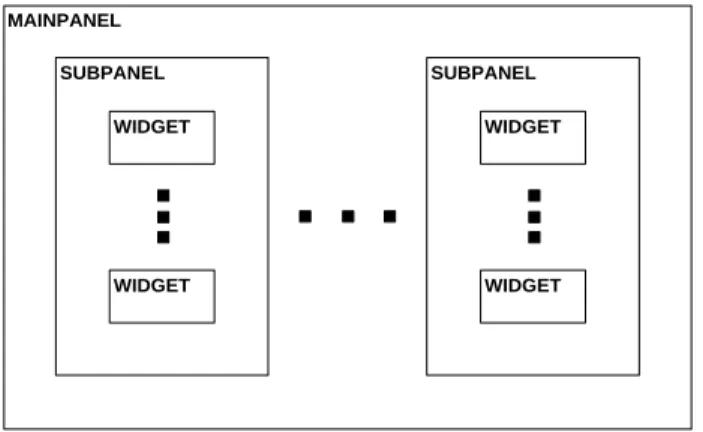
The Virtual Cockpit contains of three main components: MainPanel, SubPanel and Widget. Figure 1 shows the in-terrelation between these three components. The Main-Panel should be understood as a top-level container. It contains SubPanels, which are in turn containers for our Widgets.
The Widget itself is our primary interaction element. Panels and bars (e.g taskbar, menubar) should be under-stood only as frames of reference, therefore their shape will not be rendered. The user will only see their rendered 3D components, in most cases Widgets. In this way, you can see parts of the scene between the Widgets and it guar-antees as much as possible a non obstructed view.
With the concept of using a homogeneous style through-out all components, we had the idea to help the user associ-ating user interface parts always with a specific geometric
MAINPANEL SUBPANEL WIDGET WIDGET SUBPANEL WIDGET WIDGET
Figure 1: Shows a block diagram of Virtual Cockpit’s main components
shape. Particularly when dealing with complex scenes and lots of different shaped objects this should help for orien-tation. For our project we picked the sphere as a repre-sentation of a Widget, because we think it symbolizes the most confided and tangible shape. Next, we will address the characteristics of the main components in detail.
3.1.2 MainPanel
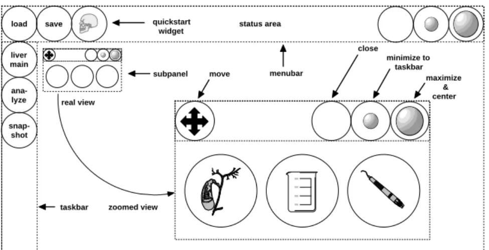
As already stated, the MainPanel is the top-level container for everything. We decided to align it in parallel to the viewing plane and to have it head-fixed. A well known approach from the desktop-metaphor is also taken into ac-count here - the use of a taskbar and menubar (see also figure 2).
The taskbar is aligned along the left viewing area border and contains one or more iconized SubPanels. To present them distinguishable the title of the SubPanel is used. The taskbar is able to become a scrollable bar, if the amount of iconized SubPanels requires more space then available. The taskbar disappears when the MainPanel is minimized. Additionally the menubar is aligned to the upper bor-der of the viewing area. It offers known desktop func-tionality like the system menu, quickstart area, status area and elements to minimize, maximize and close a panel. If the MainPanel becomes minimized solely this bar remains visible.
The quickstart area is used to provide instant access to selected SubPanels, menus or tools even after minimizing the MainPanel.
As we are using a hierarchical menu structure it is es-sential to give the user feedback about the current active level of the menu. The fact that each SubPanel and Wid-get can have a title is used to display this position in the menu’s status area by using a special notation.
Another feature of the menubar is to load new SubPan-els or their layouts and to save customized layouts. A de-tailed description of this is given later in section 3.1.6.
SubPanels reside in the remaining space of the Main-Panel (the whole viewing-area except menubar and
taskbar) and are freely movable, similar to the behavior of multi-modal applications from desktop.
3.1.3 SubPanel
The primary function of the SubPanel is to group Wid-gets (see also figure 3). Complex menus are split in small, logically related partitions. One SubPanel can therefore correlate with one of these partitions. For our example ap-plication, this could be one for liver analyzing. It would contain Widgets used for volume calculations of liver tu-mors.
Beside Widgets, the SubPanel also contains an iconbar, which uses widgets to minimize, maximize, close or move the current SubPanel. If it becomes minimized it disap-pears to the taskbar, if maximized it will be enlarged and per default positioned in the center of the viewing area to guarantee an easy interaction. To support individual changes to the user interface, SubPanels can be closed or simply be loaded at runtime (see also section 3.1.6).
3.1.4 Widget
The most elementary part of the Virtual Cockpit is the Widget element, represented by a specific object. It is ca-pable of visualizing a billboard at its center and in con-junction with the menubar title this should give enough information to show the widget’s function. Furthermore we distinguish between Widgets representing menus and Widgets for executing other actions, which we call ac-tion Widgets. 2D widgets are simply visualized in 3D by finding mappings for pushbuttons, sliders(dials), toggle-buttons and radiotoggle-buttons.
3.1.5 Hierarchies
Our hierarchical tree structure is based on the fact, that every Widget is a node in a tree, capable of having any numbers of children. Whereas every action Widget can be seen as leaf in this tree. If menus and submenus are needed, then they correspond to the inner nodes of our structure (see also figure 4). For example, consider an ob-ject’s cutting-plane snapshot. The leaf Widget’s billboard could show a low resolution version and when we click on it, we can show a high resolution version projected on the PIP. This should only be seen as a representative example for many other possible cases.
3.1.6 Customization
During application prototyping a great amount of time was invested just for the layout of the widgets on the PIP. We recognized that many approaches neglected the fact that user interfaces have to be designed and their elements must be arranged. This is difficult if it has to be done in text files or even hard coded, because results are not imme-diately viewable. It may work for smaller, simple user interfaces but is hard when they become more complex.
status area save load liver main ana-lyze close minimize to taskbar maximize & center move quickstart widget taskbar menubar subpanel zoomed view real view snap-shot
Figure 2: Shows a typical configuration of the MainPanel with taskbar, menubar and a SubPanel
Figure 3: Shows a typical SubPanel with its widgets
The “Studierstube” provides customization by using Troll-tech’s QT-Designer, but have still some problems with it. To overcome this drawbacks, we offer two choices:
Scripting simple scripting based on OpenInventor (OIV)
style, similar the way the PIP offers, but without the need to specify coordinates, which is optional.
WYSIWYG arranging SubPanels in a WYSIWYG
man-ner, while using the application
Due to the fact the PIP is integrated in the “Studier-stube” it is also based on OpenInventor. Therefore wid-get arrangements of the PIP are described as OpenInventor nodes and are read from a file during initialization. This can be done with a simple text file, but the drawback is you have to specify the coordinates all by hand. Our Vir-tual Cockpit does basically the same, but aligns Widgets and SubPanels automatically. When going this way we had the following idea: Due to the usage of hierarchies, a SubPanel contains hardly more than six top-level widgets an average. In addition the SubPanels logically separate the user interface functions. Therefore its enough to align SubPanels and widgets in a regular grid. This is sufficient, because menu structure is given through hierarchies rather than SubPanels.
Scripting user interfaces with SubPanels is easily done. Each has attributes for a short title as well as alignment,
liver main ana-lyze snap-shots modify
Figure 4: Shows the hierarchical tree structure of an ex-ample menu widget
given by upper neighbor and left neighbor or explicit with coordinates. Neighbors are specified by their short title. A SubPanels Widget is completely automatically aligned in top-left bottom-right row-wise order. When the appli-cation starts, a simple algorithm computes the needed real coordinates, saves them for later use and aligns SubPanels and Widgets.
Users need a chance to customize it to their own pref-erences. In this context we offer the opportunity to load additional pre-scripted SubPanels or even whole layouts. In addition you can save your currently used SubPanels as your very personal layout. Only customizing your Wid-gets and hierarchies is currently not supported.
3.2
Interaction
To get a better understanding of typical interaction tasks in the Virtual Cockpit, we pick the most common and impor-tant tasks and discuss them in detail.
3.2.1 Small Widgets ”growing up”
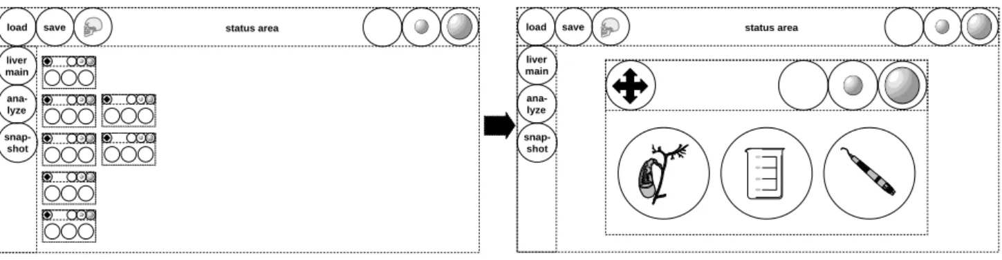
Never obstruct the scene, whenever it is possible. With this in mind, we had to find a way to make our SubPanels as
status area save load liver main ana-lyze snap-shot status area save load liver main ana-lyze snap-shot
Figure 5: Shows the Virtual Cockpit before (left) and after (right) a SubPanel was selected
small as possible but keep them also very easy navigable. We found the solution in enlarging them when needed. If a SubPanel is focused, whether clicked on or just aimed by the tip of the pen, all other SubPanels become invisible. Figure 5 shows how only the selected one gets bigger and centered in the view area. Due to the fact that examining the scene during menu navigation is not necessary, we im-prove easy navigation, without taking serious drawbacks.
3.2.2 ”Flying” Through The Menus
A SubPanel in its maximized state shows always Widgets of only one level of the tree structure. If nothing was done before, these are the roots of the Widgets (top-level Wid-gets) by default. If a Widget is selected, it is first checked if it is a leaf. If this is not the case, the SubPanel shows the children of this inner node. But in case it is a leaf, the func-tion of this acfunc-tion Widget is executed. Regardless if it was a pushbutton, slider or an other Widget, the corresponding executed function has to be defined in the custom applica-tion and will be used per callback. Addiapplica-tional descripapplica-tion of the event handling system is available at “Studierstube” research group at Vienna University of Technology [20].
Every leaf Widget contains in its definition the informa-tion, what should happen to the SubPanel if a Widget is se-lected. We defined three states: minimize to taskbar, align at corner X and by default align at center. The second one can come in handy, if you want to see an action Widget and the scene at same time, like when using transparency sliders.
Walking in the hierarchies is done easily. To get one step back you simply click in the SubPanel’s free space and the parent widget’s level will be active. Taking one step back from the root level normalizes the SubPanel and all other SubPanels are visible again. If we want to nor-malize without going back all steps, we simply click in the MainPanel’s free space.
3.2.3 Taskbar and Quickstart
If a SubPanel moves to the taskbar because of minimiza-tion, it is visualized by a sphere, showing the panel’s title at its center. A selected panel from the taskbar becomes
maximized again but always with the last active widget level.
The same is true for the quickstart area, their SubPanels or widgets are visualized similar. To add a new element to the quickstart area, simply click on an open spot and next on the desired panel or one of its widgets. A simple drag and drop to the MainPanels free space is enough to delete them, when no longer used.
3.3
Implementation Aspects
The Virtual Cockpit is integrated into the “Studierstube”, hence it is based on the graphic library OpenInventor. For detailed explanation of the OpenInventor scenegraph, we refer to this book [18]. The “Studierstube” was developed with strict object orientation in mind therefore it is quiet easy to add new components. A lot of helpful high-level and low-level classes can be used, beginning with track-ing support up to a very good user interface event system. Next, we want to give a short overview how the most im-portant components of the Virtual Cockpit integrate into the “Studierstube” library.
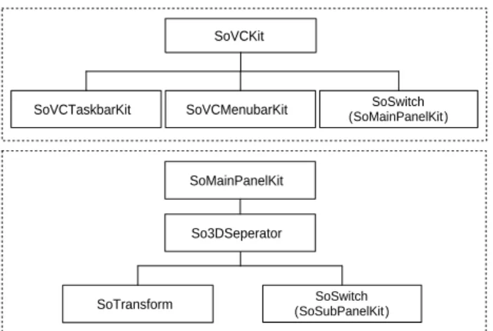
The implemented modules of the Virtual Cockpit, SoVCKit, is integrated the same way as the PIP and uses therefore similar procedures on creation, initialization and destruction. Hence it also extends the class SoTrackedAr-tifactKit and uses an attribute to specify the tracked object, which should be connected to the transform matrix of So-TrackedArtifactKit. As a result the matrix of our SoVCKit is automatically adjusted to the position of the tracked ob-ject, in our case the user’s head. The term ”kit” is OpenIn-ventor convention and is used for nodes (classes), if they should be a container for many nodes. You can see some examples with SoVCKit and SoMainPanelKit in figure 6.
The class SoMainPanelKit extends like the later men-tioned SoSubPanelKit class SoBaseKit. This is the base class for containers, SoTrackedArtifactKit also extends it. The So3DSeperator node is necessary to prevent the “Studierstube” event system from sending events not ad-dressed to the MainPanel’s bars, through all subgraphs and therefore all SubPanels. Otherwise we would suffer from a huge performance loss. Widget’s are implemented by the class SoVCWidgetKit. Their hierarchical menu structure is
SoVCKit
SoVCTaskbarKit SoVCMenubarKit (SoMainPanelKit)SoSwitch
SoMainPanelKit
SoTransform (SoSubPanelKit )SoSwitch
So3DSeperator
Figure 6: Shows the OIV kit catalog structure for nodes (classes) SoVCKit and SoMainPanelKit
SoVCWidgetKit So3DSeperator SoSwitch (SoVCWidgetKit) SoSubPanelKit So3DSeperator
SoTransform SoVCIconbarKit (SoVCWidgetKit)SoSwitch
Figure 7: Shows the OIV kit catalog structure for nodes (classes) SoSubPanelKit and SoVCWidgetKit
realized by using a SoSwitch. You can see the details of SoSubPanelKit and SoVCWidgetKit in figure 7.
We are using the existing 3D event system of “Studier-stube”. Nodes (classes) that should be aware of events simply have to extend SoBehaviorKit. This way our SoVCWidgetKit also extends this class and represents our new base class for action Widgets like pushbuttons, toggle-buttons, radiobuttons and sliders (dials). In addition, each Widget has several geometry states and the current ren-dered is always determined by combination of the states focused and selected.
4
Conclusions
We have presented a design of an alternative approach to current AR user interfaces. It features a hierarchical menu structure, which provides flexible and fast navigation in even complex user interfaces. Furthermore we showed how this can lead to a vast decrease of time in realizing interface layouts, by using our semi-automatic alignment
methods. Our project has reached end of its design phase and implementation is currently under way.
5
Future Work
For future work we will first concentrate on an evaluation of the implemented Virtual Cockpit. After that we will focus on the development of a new interaction device, to support the style of navigation possible with our system. A scroll pen will be used, most likely with a pressure sen-sitive wheel, similar to a common desktop mouse and two additional buttons. This will allow us navigation through menus by simple scroll’n click, without the need to move the hand a lot.
6
Acknowledgements
This project was done as part of the Seminar/Project at the Institute for Computer Graphics and Vision, Graz Univer-sity of Technology. I would like to thank Bernhard Re-itinger for all his help and encouragements.
References
[1] R. Azuma. A survey of augmented reality. In Computer Graphics (SIGGRAPH ’95 Proceedings, Course Notes #9: Developing Advanced Virtual Re-ality Application), pages 1–38, 1995.
[2] A. Bornik, R. Beichel, B. Reitinger, G. Gotschuli, E. Sorantin, F. Leberl, and M. Sonka. Computer aided liver surgery planning: An augmented reality approach. In R.L. Galloway, editor, Medical Imag-ing 2003, ProceedImag-ings of SPIE, volume 5029. SPIE Press, May 2003.
[3] D. Bowman, L. Hodges, and J. Bolter. The virtual venue: User-computer interaction in information-rich virtual environments. PRESENCE, 7(5):478– 493, 1998.
[4] A. Butz, T. H¨ollerer, S. Feiner, B. MacIntyre, and C. Beshers. Enveloping users and computers in a collaborative 3d augmented reality. In 2nd IEEE and ACM International Workshop on Augmented Reality, 1999.
[5] R. Dachselt. Action spaces - a metaphorical concept to support navigation and interaction in 3d interfaces. In Workshop Usability Centred Design and Evalua-tion of Virtual 3D Environments, 2000.
[6] M. Deering. The holosketch VR sketching system. Comm. of the ACM, 39(5):55–61, 1996.
[7] L. Serra et al. Medicine Meets Virtual Reality, chap-ter An inchap-terface for precise and comfortable 3D work with volumetric medical datasets, pages 329–334. IOS Press, 1999.
[8] S. Feiner, B. MacIntyre, M. Haupt, and E. Solomon. Windows on the world: 2d windows for 3d aug-mented reality. In ACM Symposium on User Inter-face Software and Technology, pages 145–155, 1993. [9] M. Ferneau and J. Humphries. A gloveless interface for interaction in scientific visualization virtual en-vironments. In Proceedings of SPIE, Stereoscopic Displays and Virtual Reality Systems, volume 2409, pages 268–274, 1995.
[10] R. Jacoby and S. Ellis. Using virtual menus in a virtual environment. In Proceedings of SPIE, Vi-sual Data Interpretation, volume 1668, pages 39–48, 1992.
[11] H. Kato and M. Billinghurst. Marker tracking and HMD calibration for a video-based augmented re-ality conferencing system. In Proceedings Interna-tional Workshop on Augmented Reality (IWAR’99), pages 85–94, 1999.
[12] J. Liang and M. Green. JDCAD: A highly interac-tive 3d modeling system. Computer and Graphics, 18(4):499–506, 1994.
[13] J. Pierce, M. Conway, M. van Dantzich, and G. Robertson. Toolspaces and glances: storing, ac-cessing, and retrieving objects in 3d desktop appli-cations. In Proceedings of the 1999 Symposium on Interactive 3D Graphics, pages 163–168, 1999. [14] G. Robertson, M. van Dantzich, D. Robbins, M.
Cz-erwinski, K. Hinckley, K. Risden, D. Thiel, and V. Gorokhovsky. The task gallery: a 3d window man-ager. In Proc. of the CHI 2000 conference on Human factors in computing systems, pages 494–501, 2000. [15] D. Schmalstieg, A.L. Fuhrmann, Z. Szalavari, and
M. Gervautz. Studierstube - an environment for col-laboration in augmented reality. In Proceedings of Collaborative Virtual Environments, pages 19–20, 1996.
[16] H. Sowizral. Interacting with Virtual Environments Using Augmented Virtual Tools, chapter Stereo-scopic Displays and Virtual Reality Systems, pages 28–34. Fisher, 1994.
[17] Z. Szalavari and M. Gervautz. The personal inter-action panel - a two-handed interface for augmented reality. Computer Graphics Forum, 16(3):335–346, 1997.
[18] J. Wernecke and I. Mentor. Programming Object-Oriented 3D Graphics with OpenInventor. Addison-Wesley, 1994.
[19] M. Wloka and E. Greenfield. The virtual tricorder: A uniform interface for virtual reality. In ACM Sym-posium on User Interface Software and Technology, pages 39–40, 1995.
[20] A. Zajic. Application management for three-dimensional user interfaces. Master’s thesis, Inter-active Media Systems Group, Vienna University of Technology, 2003.