TECHNICAL REPORT
DSL Forum
TR-069
CPE WAN Management Protocol
May 2004
Produced by:
DSLHome-Technical Working Group
Editors:
Jeff Bernstein, 2Wire
Tim Spets, Westell
Working Group Co-Chairs:
Greg Bathrick, Texas Instruments
George Pitsoulakis, Westell
Abstract:
A protocol for communication between a CPE and Auto-Configuration Server (ACS) that
encompasses secure auto-configuration as well as other CPE management functions
within a common framework.
Notice:
The DSL Forum is a non-profit corporation organized to create guidelines for DSL network system
development and deployment. This Technical Report has been approved by members of the Forum. This
document is not binding on the DSL Forum, any of its members, or any developer or service provider
involved in DSL. The document is subject to change, but only with approval of members of the Forum.
©2001 Digital Subscriber Line Forum. All Rights Reserved.
DSL Forum technical reports may be copied, downloaded, stored on a server or otherwise re-distributed in
their entirety only.
Notwithstanding anything to the contrary, the DSL Forum makes no representation or warranty, expressed
or implied, concerning this publication, its contents or the completeness, accuracy, or applicability of any
information contained in this publication. No liability of any kind shall be assumed by the DSL Forum as a
result of reliance upon any information contained in this publication. The DSL Forum does not assume any
responsibility to update or correct any information in this publication.
The receipt or any use of this document or its contents does not in any way create by implication or
otherwise any express or implied license or right to or under any patent, copyright, trademark or trade
secret rights which are or may be associated with the ideas, techniques, concepts or expressions contained
herein.
NOTE: The user's attention is called to the possibility that compliance with this report may require use of
an invention covered by patent rights.
By publication of this report, no position is taken with respect to the validity of the claim or of any patent
rights in connection therewith. The patent holder has, however, filed a statement of willingness to grant a
license under these rights on reasonable and nondiscriminatory terms and conditions to applicants desiring
to obtain such a license. Details may be obtained from the publisher.
Contents
1
Introduction ... 6
1.1
Functional Components ... 6
1.1.1
Auto-Configuration and Dynamic Service Provisioning ... 6
1.1.2
Software/Firmware Image Management ... 6
1.1.3
Status and Performance Monitoring... 6
1.1.4
Diagnostics ... 7
1.1.5
Identity Management for Web Applications... 7
1.2
Positioning in the Auto-Configuration Architecture ... 7
1.3
Security Goals ... 8
1.4
Architectural Goals ... 8
1.5
Assumptions... 9
1.6
Terminology... 9
1.7
Document Conventions ...10
2
Architecture...10
2.1
Protocol Components...10
2.2
Security Mechanisms ...11
2.2.1
Security Initialization Models ...11
2.3
Architectural Components ...12
2.3.1
Parameters ...12
2.3.2
File Transfers ...12
2.3.3
CPE Initiated Notifications...13
2.3.4
Asynchronous ACS Initiated Notifications ...13
3
Procedures and Requirements ...13
3.1
ACS Discovery ...13
3.2
Connection Establishment...14
3.2.1
CPE Connection Initiation ...14
3.2.2
ACS Connection Initiation ...15
3.3
Use of SSL/TLS and TCP ...16
3.4
Use of HTTP...16
3.4.1
Encoding SOAP over HTTP...16
3.4.2
Transaction Sessions...17
3.4.3
File Transfers ...18
3.4.4
Authentication ...18
3.5
Use of SOAP ...18
3.6
RPC Support Requirements ...22
3.7
Transaction Session Procedures...22
3.7.1
CPE Operation ...23
3.7.2
ACS Operation ...24
3.7.3
Transaction Examples...26
Normative References ...28
Appendix A.
RPC Methods ...29
A.1
Introduction ...29
A.2
RPC Method Usage ...29
A.2.1
Data Types ...29
A.2.2
Other Requirements ...30
A.3
Baseline RPC Messages ...30
A.3.1
Generic Methods ...30
A.3.1.1
GetRPCMethods ...30
A.3.2
CPE Methods ...31
A.3.2.1
SetParameterValues ...31
A.3.2.2
GetParameterValues...32
A.3.2.3
GetParameterNames ...33
A.3.2.4
SetParameterAttributes...33
A.3.2.6
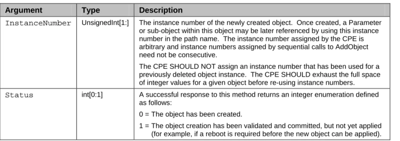
AddObject ...36
A.3.2.7
DeleteObject ...37
A.3.2.8
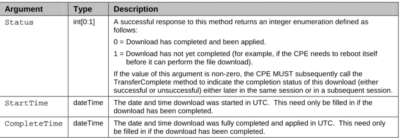
Download ...38
A.3.2.9
Reboot ...39
A.3.3
Server Methods ...40
A.3.3.1
Inform...40
A.3.3.2
TransferComplete ...43
A.4
Optional RPC Messages...44
A.4.1
CPE Methods ...44
A.4.1.1
GetQueuedTransfers ...44
A.4.1.2
ScheduleInform ...44
A.4.1.3
SetVouchers ...45
A.4.1.4
GetOptions...45
A.4.1.5
Upload...46
A.4.1.6
FactoryReset...47
A.4.2
Server Methods ...47
A.4.2.1
Kicked ...47
A.4.2.2
RequestDownload...48
A.5
Fault Handling ...49
A.5.1
CPE Fault Codes...49
A.5.2
Server Fault Codes ...49
A.5.3
Server Method Retry Behavior ...50
Appendix B.
CPE Parameters...51
B.1
Introduction ...51
B.2
CPE Parameters ...51
B.2.1
Data Types ...52
B.2.2
Vendor-Specific Parameters ...52
B.2.3
Parameter List ...53
Appendix C.
Signed Vouchers ...91
C.1
Overview ...91
C.2
Control of Options Using Vouchers ...91
C.3
Voucher Definition...91
Appendix D.
Web Identity Management ...96
D.1
Overview ...96
D.2
Use of the Kicked RPC Method ...96
D.3
Web Identity Management Procedures ...96
D.4
LAN Side Interface ...97
Appendix E.
Signed Package Format ...99
E.1
Introduction ...99
E.2
Signed Package Format Structure ...99
E.2.1
Encoding Conventions ...100
E.3
Header Format ...100
E.4
Command List Format...100
E.4.1
Command Types ...100
E.4.2
End Command ...101
E.4.3
Extract and Add Commands ...102
E.4.4
Remove Commands...102
E.4.8
Reboot Command ...106
E.4.9
Format File System ...106
E.4.10
Minimum and Maximum Version Commands ...106
E.4.11
Role Command ...107
E.4.12
Minimum Storage Commands ...107
E.4.13
Required Attributes Command ...108
1 Introduction
This document describes the CPE WAN Management Protocol, intended for communication between a
CPE and Auto-Configuration Server (ACS). The CPE WAN Management Protocol defines a mechanism
that encompasses secure auto-configuration of a CPE, and also incorporates other CPE management
functions into a common framework.
1.1 Functional
Components
The CPE WAN Management Protocol is intended to support a variety of functionalities to manage a
collection of CPE, including the following primary capabilities:
•
Auto-configuration and dynamic service provisioning
•
Software/firmware image management
•
Status and performance monitoring
•
Diagnostics
1.1.1 Auto-Configuration and Dynamic Service Provisioning
The CPE WAN Management Protocol allows an ACS to provision a CPE or collection of CPE based on a
variety of criteria. The provisioning mechanism includes specific provisioning parameters and a general
mechanism for adding vendor-specific provisioning capabilities as needed.
The provisioning mechanism allows CPE provisioning at the time of initial connection to the broadband
access network, and the ability to re-provision at any subsequent time. This includes support for
asynchronous ACS-initiated re-provisioning of a CPE.
The identification mechanisms included in the protocol allow CPE provisioning based either on the
requirements of each specific CPE, or on collective criteria such as the CPE vendor, model, software
version, or other criteria.
The protocol also provides optional tools to manage the CPE-specific components of optional applications
or services for which an additional level of security is required to control, such as those involving
payments. The mechanism for control of such Options using digitally signed Vouchers is defined in
Appendix C.
The provisioning mechanism allows straightforward future extension to allow provisioning of services and
capabilities not yet included in this version of the specifications.
1.1.2 Software/Firmware Image Management
The CPE WAN Management Protocol provides tools to manage downloading of CPE software/firmware
image files. The protocol provides mechanisms for version identification, file download initiation (ACS
initiated downloads and optional CPE initiated downloads), and notification of the ACS of the success or
failure of a file download.
The CPE WAN Management Protocol also defines a digitally signed file format that may optionally be
used to download either individual files or a package of files along with explicit installation instructions for
the CPE to perform. This signed package format ensures the integrity of downloaded files and the
associated installation instructions, allowing authentication of a file source that may be a party other than
the ACS operator.
1.1.3 Status and Performance Monitoring
parameters that an ACS can monitor. It also defines a set of conditions under which a CPE should actively
notify the ACS of changes.
1.1.4 Diagnostics
The CPE WAN Management Protocol provides support for a CPE to make available information that the
ACS may use to diagnose connectivity or service issues. The protocol defines a common set of such
parameters and a general mechanism for adding vendor-specific diagnostic capabilities.
1.1.5 Identity Management for Web Applications
To support web-based applications for access from a browser within the CPE’s local network, the CPE
WAN Management Protocol defines an optional mechanism that allows such web sites to customize their
content with explicit knowledge of the associated CPE. This mechanism is described in Appendix D.
1.2 Positioning in the Auto-Configuration Architecture
TR-046 [2] describes the overall framework for B-NT auto-configuration. This process consists of three
sequential stages, each of which is focused on a specific aspect of the overall B-NT auto-configuration
process.
The procedures for the first two stages of B-NT auto-configuration are specified in TR-062 [3] and TR-044
[4]. These define the ATM layer and IP layer auto-configuration procedures, respectively, used to initiate
basic broadband connectivity.
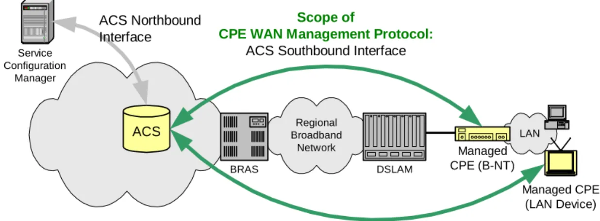
The third stage of auto-configuration defined in TR-046 covers “auto-configured complex services.” In the
case of a B-NT, the CPE WAN Management Protocol relates primarily to this third stage. Specifically, the
CPE WAN Management Protocol is proposed as the protocol to be used on the
ACS-Southbound Interface
between an Auto-Configuration Server (ACS), and a B-NT as shown in Figure 1.
Note—in the case of a B-NT, contrary to the nested model of TR-046, this protocol also allows
configuration of ATM Layer parameters if an alternative auto-configuration protocol is not in use,
e.g., as defined in TR-062. However, if an alternative is in use then configuration of the ATM
Layer parameters by this protocol is disabled.
In addition to configuration, the protocol provides a means of extracting diagnostic and
performance monitoring data from the ATM layer and the DSL modem. Again this is contrary to
the nested model described in TR-046, but provides an alternative means of accessing information
that can already be obtained through existing management protocols, i.e., ILMI and the EOC of
the DSL link. The provision of more advanced diagnostic and performance monitoring
functionality via this protocol is a subject for further study.
While the CPE WAN Management Protocol is targeted at management of B-NTs, this protocol may be
used to manage other types of CPE as well, including stand-alone routers and LAN-side client devices, as
also shown in Figure 1. Unless otherwise indicated, the CPE WAN Management Protocol as defined in
this specification applies to any such managed device. Portions of this specification that apply only to a
B-NT are explicitly indicated in the text. This specification includes a complete definition of the CPE
parameter model for a B-NT. The corresponding parameter model for other specific device types is beyond
the scope of this specification.
Figure 1 – Positioning in the Auto-Configuration Architecture
LAN Managed CPE (B-NT) Regional Broadband Network DSLAM BRASACS
Scope of
CPE WAN Management Protocol:
ACS Southbound Interface
Service Configuration Manager
ACS Northbound
Interface
Managed CPE (LAN Device)1.3 Security
Goals
The CPE WAN Management Protocol is designed to provide a high degree of security. The security model
is also designed to be scalable. It is intended to allow basic security to accommodate less robust CPE
implementations, while allowing greater security for those that can support more advanced security
mechanisms. In general terms, the security goals of the CPE WAN Management Protocol are as follows:
•
Prevent tampering with the management functions of a CPE or ACS, or the transactions that take place
between a CPE and ACS.
•
Provide confidentiality for the transactions that take place between a CPE and ACS.
•
Allow appropriate authentication for each type of transaction.
•
Prevent theft of service.
1.4 Architectural
Goals
The protocol is intended to provide flexible support for various business models for distributing and
managing CPE, including:
•
CPE provided and managed by the network provider.
•
CPE purchased in retail with pre-registration to associate the specific CPE with a service provider and
customer account (a mobile-phone like model)
•
CPE purchased in retail with post-installation user registration with a service provider.
The protocol is intended to provide flexibility in the connectivity model. The protocol is intended to
provide the following:
•
Allow both CPE and ACS initiated connection establishment, avoiding the need for a persistent
connection to be maintained between each CPE and an ACS.
•
The functional interactions between the ACS and CPE should be independent of which end initiated
the establishment of the connection. In particular, even where ACS initiated connectivity is not
supported, all ACS initiated transactions should be able to take place over a connection initiated by the
CPE.
•
Optimize the use of connections that are established to minimize connection overhead by allowing
multiple bi-directional transactions to occur over a single connection.
The protocol is intended to support discovery and association of ACS and CPE:
•
Provide mechanisms for a CPE to discover the appropriate ACS for a given service provider.
•
Provide mechanisms to allow an ACS to securely identify a CPE and associate it with a user/customer.
Processes to support such association should support models that incorporate user interaction as well as
those that are fully automatic.
The protocol model to allow an ACS access to control and monitor various parameters associated with a
CPE. The mechanisms provided to access these parameters is designed with the following premises:
•
Different CPE may have differing capability levels, implementing different subsets of optional
functionality. As a result, an ACS must be able to discover the capabilities of a particular CPE.
•
An ACS must be able to control and monitor the current configuration of a CPE.
•
Other control entities besides an ACS may be able to control some parameters of a CPE’s
configuration (e.g., via LAN-side auto-configuration). As a result, the protocol must allow an ACS to
account for external changes to a CPE’s configuration. The ACS should also be able to control which
configuration parameters can be controlled via means other than by the ACS.
•
The protocol should allow vendor-specific parameters to be defined and accessed.
The protocol is intended to minimize implementation complexity, while providing flexibility in trading off
complexity vs. functionality. The protocol incorporates a number of optional components that come into
play only if specific functionality is required. The protocol also incorporates existing standards where
appropriate, allowing leverage of off-the-shelf implementations.
The protocol is also designed to be extensible. It includes mechanisms to support future extensions to the
standard, as well as explicit mechanisms for vendor-specific extensions.
1.5 Assumptions
Some assumptions made in defining the CPE WAN Management Protocol are listed below:
•
In the case of a B-NT, prior to use of the CPE WAN Management Protocol, initial B-NT
auto-configuration as defined in TR-062 [3] and TR-044 [4] has been completed and a connection has been
established to a WAN from which an ACS is accessible.
•
All CPE regardless of type (bridge
1, router, or other) obtain an IP address in order to communicate
with an ACS.
•
A CPE can interact with a single ACS at a time. At any time, a CPE is aware of exactly one ACS with
which it can connect. An ACS can hand off a CPE to another ACS only by explicitly altering the ACS
contact and authentication information. (Note: a collection of ACS servers behind a load balancer is
considered a single ACS for the purposes of this document.)
1.6 Terminology
The following terminology is used throughout the series of documents defining the CPE WAN
Management Protocol.
ACS
Auto-Configuration Server. This is a component in the broadband network responsible
for auto-configuration of the CPE for advanced services.
1
In the case of a bridge, the CPE must establish IP-layer connectivity specifically for management
communication. The mechanism used to establish this connectivity would depend on the specific
network architecture. For example, a bridge may connect using IPoE with DHCP for address allocation,
B-NT
A broadband access CPE device capable of being managed by an ACS.
CPE
Customer Premise Equipment. A DSL B-NT is one form of broadband CPE.
Internet
Gateway
Device
A CPE device that is either a B-NT or a broadband router.
Option
An optional CPE capability that may only be enabled or disabled using a digitally signed
Voucher.
RPC
Remote procedure call.
Parameter
A name-value pair representing a manageable CPE parameter made accessible to an ACS
for reading and/or writing.
Session
A contiguous sequence of transactions between a CPE and an ACS.
Voucher
A digitally signed data structure that instructs a particular CPE to enable or disable
Options, and characteristics that determine under what conditions the Options persist.
1.7 Document
Conventions
The key words "MUST", "MUST NOT", "REQUIRED", "SHALL", "SHALL NOT", "SHOULD",
"SHOULD NOT", "RECOMMENDED", "MAY", and "OPTIONAL" in this document are to be
interpreted as described in [1].
2 Architecture
2.1 Protocol
Components
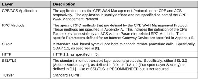
The CPE WAN Management Protocol comprises several components that are unique to this protocol, and
makes use of several standard protocols. The protocol stack defined by the CPE WAN Management
Protocol is shown in Figure 2. A brief description of each layer is provided in Table 1.
Figure 2 – Protocol stack
CPE/ACS Management Application
RPC Methods
SOAP
HTTP
SSL/TLS
Table 1 – Protocol layer summary
Layer
Description
CPE/ACS Application The application uses the CPE WAN Management Protocol on the CPE and ACS, respectively. The application is locally defined and not specified as part of the CPE WAN Management Protocol.
RPC Methods The specific RPC methods that are defined by the CPE WAN Management Protocol. These methods are specified in Appendix A. This includes the definition of the CPE Parameters accessible by an ACS via the Parameter-related RPC Methods. The specific Parameters defined for an Internet Gateway Device are specified in Appendix B. SOAP A standard XML-based syntax used here to encode remote procedure calls. Specifically
SOAP 1.1, as specified in [8]. HTTP HTTP 1.1, as specified in [5].
SSL/TLS The standard Internet transport layer security protocols. Specifically, either SSL 3.0 (Secure Socket Layer), as defined in [10], or TLS 1.0 (Transport Layer Security) as defined in [11]. Use of SSL/TLS is RECOMMENDED but is not required.
TCP/IP Standard TCP/IP.
2.2 Security
Mechanisms
The CPE WAN Management Protocol is designed to allow a high degree of security in the interactions that
use it. The CPE WAN Management Protocol is designed to prevent tampering with the transactions that
take place between a CPE and ACS, provide confidentiality for these transactions, and allow various levels
of authentication.
The following security mechanisms are incorporated in this protocol:
•
The protocol supports the use of SSL/TLS for communications transport between CPE and ACS. This
provides transaction confidentiality, data integrity, and allows certificate-based authentication between
the CPE and ACS.
•
The HTTP layer provides an alternative means of CPE authentication based on shared secrets.
The protocol includes additional security mechanisms associated with the optional signed Voucher
mechanism and the Signed Package Format, described in Appendix C and Appendix E, respectively.
2.2.1 Security Initialization Models
Initialization of the security mechanisms is described in the context of various business models for CPE
distribution. Three models are considered:
•
Distribution of CPE by the service provider associated with the ACS.
•
Retail distribution of the CPE, where association of the CPE with the service provider and customer is
done at the time of purchase.
•
Retail distribution where no pre-association with the CPE is done.
In the first two cases, the specific identity of the CPE can be known to the ACS before the CPE is first
used. In these cases, the following mechanisms may be used:
Authentication
of
Type used
Description
Shared secret Shared secret must be pre-loaded into CPE before the first use of the CPE. ACS
Certificate Discovery of the ACS URL as described in section 3.1 uniquely identifies the identity of the ACS for the purpose of certificate validation.
Shared secret Shared secret must be provided to the ACS before the first use of the CPE. CPE
Certificate The CPE may use online certificate enrollment with the CA associated with the ACS. The CPE must be provided with the information needed to contact this CA.
In the latter case of retail distribution of the CPE, there is no possibility of pre-association of the CPE with
a particular ACS. The following table presents possible approaches to accommodating this case, but does
not attempt to mandate a specific approach:
Authentication
of
Type used
Description
Shared secret Not appropriate for this case. ACS
Certificate Discovery of the ACS URL as described in section 3.1 uniquely identifies the identity of the ACS for the purpose of certificate validation.
Shared secret Possible alternatives, outside the scope of this specification:
• Establish a common server for secure distribution of CPE shared secrets among multiple service providers.
• Initial CPE to ACS connection of an unrecognized CPE could be allowed without authentication. ACS would then set the shared secret Parameter for subsequent access. Care in ACS implementation would be required to prevent denial of service attacks.
CPE
Certificate The CPE may use online certificate enrollment with the CA associated with the ACS. The CPE must be provided with the information needed to contact this CA, which could be incorporated into the discovery process.
2.3 Architectural
Components
2.3.1 Parameters
The RPC Method Specification (see Appendix A) defines a generic mechanism by which an ACS can read
or write Parameters to configure a CPE and monitor CPE status and statistics. The particular list of defined
Parameters for an Internet Gateway Device is specified in Appendix B.
Each Parameter consists of a name-value pair. The name identifies the particular Parameter, and has a
hierarchical structure similar to files in a directory, with each level separated by a “.” (dot). The value of a
Parameter may be one of several defined data types (see Appendix B).
Parameters may be defined as read-only or read-write. Read-only Parameters may be used to allow an
ACS to determine specific CPE characteristics, observe the current state of the CPE, or collect statistics.
Writeable Parameters allow an ACS to customize various aspects of the CPE’s operation. All writeable
Parameters must also be readable. The value of some writeable Parameters may be independently
modifiable through means other than the interface defined in this specification (e.g., some Parameters may
also be modified via a LAN side auto-configuration protocol).
The protocol supports a discovery mechanism that allows an ACS to determine what Parameters a
particular CPE supports, allowing the definition of optional parameters as well as supporting
straightforward addition of future standard Parameters.
The protocol also includes an extensibility mechanism that allows use of vendor-specific Parameters in
addition to those defined in this specification.
2.3.2 File
Transfers
The RPC Method Specification (see Appendix A) defines a mechanism to facilitate file downloads or
(optionally) uploads for a variety of purposes, such as firmware upgrades or vendor-specific configuration
files.
When initiated by the ACS, the CPE is provided with the location of the file to be transferred, using HTTP
or, optionally, HTTPS, FTP, or TFTP as the transport protocol. The CPE then performs the transfer, and
notifies the ACS of the success or failure.
Downloads may be optionally initiated by a CPE. In this case, the CPE first requests a download of a
particular file type from the ACS. The ACS may then respond by initiating the download following the
same steps as an ACS-initiated download.
The CPE WAN Management Protocol also defines a digitally signed file format that may optionally be
used for downloads. This Signed Package Format is defined in Appendix E.
2.3.3 CPE Initiated Notifications
The RPC Method Specification (see Appendix A) defines a mechanism that allows a CPE to notify a
corresponding ACS of various conditions, and to ensure that CPE-to-ACS communication will occur with
some minimum frequency.
This includes mechanisms to establish communication upon initial CPE installation, to ‘bootstrap’ initial
customized Parameters into the CPE. It also includes a mechanism to establish periodic communication
with the ACS on an ongoing basis, or when events occur that must be reported to the ACS (such as when
the broadband IP address of the CPE changes). The ACS must be aware of this event in order to establish
incoming connections to the CPE.
In each case, when communication is established the CPE identifies itself uniquely via manufacturer and
serial number information so that the ACS knows which CPE it is communicating with and can respond in
an appropriate way.
2.3.4 Asynchronous ACS Initiated Notifications
An important aspect of service auto-configuration is the ability for the ACS to notify the CPE of a
configuration change asynchronously. This allows the auto-configuration mechanism to be used for
services that require near-real-time reconfiguration of the CPE. For example, this may be used to provide
an end-user with immediate access to a service or feature they have subscribed to, without waiting for the
next periodic Inform interval.
The CPE WAN Management Protocol incorporates a mechanism for the ACS to issue a Connection
Request to the CPE at any time, instructing it to establish a communication session with the ACS.
While the CPE WAN Management Protocol also allows polling by the CPE in lieu of ACS-initiated
connections, the CPE WAN Management Protocol does not rely on polling or establishment of persistent
connections from the CPE to provide asynchronous notification.
3 Procedures and Requirements
3.1 ACS
Discovery
The CPE WAN Management Protocol defines the following mechanisms that may be used by a CPE to
discover the address of its associated ACS:
1. The CPE may be configured locally with the URL of the ACS. For example, this may be done via a
LAN-side CPE auto-configuration protocol. The CPE would use DNS to resolve the IP address of the
ACS from the host name component of the URL.
2. As part of the IP layer auto-configuration, a DHCP server on the access network may be configured to
include the ACS URL as a DHCP option [12]. The CPE would use DNS to resolve the IP address of
the ACS from the host name component of the URL. In this case a second DHCP option MAY be
used to set the ProvisioningCode, which may be used to indicate the primary service provider and
other provisioning information to the ACS.
A CPE identifies itself to the DHCP server as supporting this method by including the string
“dslforum.org” (all lower case) anywhere in the Vendor Class Identifier (DHCP option 60).
The CPE MAY use the values received from the DHCP server in the Vendor Specific Information
(DHCP option 43) to set the corresponding parameters as listed in Table 2. This DHCP option is
encoded as a list of one or more Encapsulated Vendor-Specific Options in the format defined in [12].
This list may include other vendor-specific options in addition to those listed here.
Table 2 – Encapsulated Vendor Specific Options
Encapsulated
Option
Encapsulated
Vendor-Specific Option number
Parameter
2URL of the ACS 1 InternetGatewayDevice.ManagementServer.URL Provisioning code 2 InternetGatewayDevice.DeviceInfo.ProvisioningCode
3. The CPE may have a default ACS URL that it may use if no other URL is provided to it.
The ACS URL MUST be in the form of a valid HTTP or HTTPS URL [5]. Use of an HTTPS URL
indicates that the ACS supports SSL. If an HTTPS URL is given, and the CPE that does not support SSL,
it MAY attempt to use HTTP assuming the remainder of the URL is unchanged.
Once the CPE has established a connection to the ACS, the ACS may at any time modify the ACS address
Parameter stored within the CPE (InternetGatewayDevice.ManagementServer.URL). Once modified, the
CPE MUST use the modified address for all subsequent connections to the ACS.
The “host” portion of the ACS URL is used by the CPE for validating the certificate from the ACS when
using certificate-based authentication. Because this relies on the accuracy of the ACS URL, the overall
security of this protocol is dependent on the security of the ACS URL.
The CPE SHOULD restrict the ability to locally configure the ACS URL to mechanisms that require strict
security. The CPE MAY further restrict the ability to locally set the ACS URL to initial setup only,
preventing further local configuration once the initial connection to an ACS has successfully been
established such that only its existing ACS may subsequently change this URL.
The use of DHCP for configuration of the ACS URL SHOULD be limited to situations in which the
security of the link between the DHCP server and the CPE can be assured by the service provider. Since
DHCP does not itself incorporate a security mechanism, other means of ensuring this security should be
provided.
3.2 Connection
Establishment
3.2.1 CPE Connection Initiation
The CPE may at any time initiate a connection to the ACS using the pre-determined ACS address (see
section 3.1). A CPE MUST establish a connection to the ACS and issue the Inform RPC method
(following the procedures described in section 3.7) under the following conditions:
•
The first time the CPE establishes a connection to the access network on initial installation
•
On power-up or reset
•
Once every PeriodicInformInterval (for example, every 24-hours)
•
When so instructed by the optional ScheduleInform method
•
Whenever the CPE receives a valid Connection Request from an ACS (see section 3.2.2)
•
Whenever the URL of the ACS changes
•
Whenever a parameter is modified that is required to initiate an Inform on change. In the case of
an Internet Gateway Device, this includes changes to the following (see A.3.3.1):
o
IP address of the default broadband connection
o
Management IP address (associated with the Connection Request URL)
o
Provisioning code
o
Software version
•
Whenever the value of a parameter that the ACS has marked for “active notification” via the
SetParameterAttributes method is modified by an external cause (a cause other than the ACS
itself). Parameter changes made by the ACS itself via SetParameterValues MUST NOT cause a
new session to be initiated. If a parameter is modified more than once before the CPE is able to
initiate a session to perform the notification, only one notification is performed.
If a parameter is modified by an external cause while a session is in progress, the change causes a
new session to be established after the current session is terminated (it MUST not effect the
current session).
In order to avoid excessive traffic to the ACS, a CPE MAY place a locally specified limit on the
frequency of parameter change notifications. This limit SHOULD be defined so that it is
exceeded only in unusual circumstances. If this limit is exceeded, the CPE MAY delay by a
locally specified amount initiation of a session to notify the ACS. After this delay, the CPE
MUST initiate a session to the ACS and indicate all relevant parameter changes (those parameters
that have been marked for notification) that have occurred since the last such notification.
The CPE SHOULD NOT maintain an open connection to the ACS when no more outstanding messages
exist on the CPE or ACS.
3.2.2 ACS Connection Initiation
The ACS at any time request that the CPE initiate a connection to the ACS using the Connection Request
notification mechanism. Support for this mechanism is REQUIRED in a CPE, and is RECOMMENDED
in an ACS.
This mechanism relies on the CPE having an IP address that is routable from the ACS. If the CPE is
behind a firewall or NAT device lying between the ACS and CPE, the ACS may not be able to access the
CPE at all. In this case, only CPE connection initiation is possible.
The Connection Request notification mechanism is defined as follows:
•
The Connection Request notification is an HTTP Get to a specific URL designated by the CPE. The
URL value is available as read-only Parameter on the CPE. The path of this URL value SHOULD be
randomly generated by the CPE so that it is unique per CPE.
•
The Connection Request notification MUST make use of HTTP, not HTTPS. The associated URL
MUST be an “http” URL.
•
No data is conveyed in the Connection Request HTTP Get notification. Any data that might be
contained SHOULD be ignored by the CPE.
•
The CPE SHOULD use digest-authentication to authenticate the ACS before proceeding—the CPE
SHOULD NOT initiate a connection to the ACS due to an unsuccessfully authenticated request. The
shared-secret used to authenticate the ACS is available as a modifiable Parameter on the CPE.
•
The CPE SHOULD restrict the number of Connection Request notifications it accepts during a given
period of time in order to further reduce the possibility of a denial of service attack.
•
The successful authentication of an HTTP Get to the designated port and URL causes the CPE to
perform a fixed action: it establishes a session with the pre-determined ACS address (see section 3.1),
and once connected, it sends an Inform message.
•
If the CPE is already in a session with the ACS when it receives a Connection Request notification, it
MUST NOT terminate that session prematurely as a result.
This mechanism relies on the ACS having had at least one prior communication with the CPE via a
CPE-initiated interaction. During this interaction, if the ACS wishes to allow future ACS-CPE-initiated transactions,
it would read the value of the InternetGatewayDevice.ManagementServer.ConnectionRequestURL
Parameter. If the URL used for management access changes, the CPE must notify the ACS by issuing an
Inform message indicating the new management IP address (as described in Table 33), thus keeping the
ACS up-to-date.
3.3 Use of SSL/TLS and TCP
The use of SSL/TLS to transport the CPE WAN Management Protocol is RECOMMENDED, although the
protocol may be used directly over a TCP connection instead. If SSL/TLS is not used, some aspects of
security are sacrificed. Specifically, SSL/TLS provides confidentiality and data integrity, and allows
certificate-based authentication in lieu of shared secret-based authentication.
Certain restrictions on the use of SSL/TLS and TCP are defined as follows:
•
If SSL/TLS is supported, the REQUIRED versions are SSL 3.0 [10] or TLS 1.0 [11].
•
If SSL/TLS is supported, support for encryption algorithms with key lengths greater than or equal to
128 bits SHOULD be supported.
•
A CPE MUST be able to initiate outgoing connections to the ACS.
•
An ACS MUST be able to accept CPE-initiated connections.
•
If SSL/TLS is used, the CPE MUST authenticate the ACS using the ACS-provided certificate.
•
If SSL/TLS is used, the ACS MAY accept a validated CPE-provided certificate to authenticate the
CPE, but the ACS MUST allow the SSL/TLS connection to be established if the CPE does not provide
a certificate.
3.4 Use of HTTP
SOAP messages are carried between a CPE and an ACS using HTTP 1.1 [5], where the CPE acts as the
HTTP client and the ACS acts as the HTTP server.
3.4.1 Encoding SOAP over HTTP
The encoding of SOAP over HTTP extends the basic HTTP profile for SOAP, described in [8], as follows:
•
A SOAP request from an ACS to a CPE is sent over an HTTP response, while the CPE’s SOAP
response to an ACS request is sent over a subsequent HTTP post.
•
Each HTTP post or response may contain more than one SOAP envelope (within the negotiated
limits). Each envelope may contain a SOAP request or response, independent from any other
envelope.
•
When there is more than one envelope in a single HTTP Request, the SOAPAction header in the
HTTP Request MUST have no value (with no quotes), indicating that this header provides no
information as to the intent of the message. That is, it should appear as follows:
SOAPAction:
The Inform message contains an argument called MaxEnvelopes that indicates to the ACS the maximum
number of SOAP envelopes that may be contained in a single HTTP response. The value of this parameter
may be one or greater. Once the Inform message has been received, any HTTP response from the ACS
may include at most this number of SOAP envelopes (requests or responses).
parameter may be one or greater. Once the Inform response has been received, any HTTP post from the
CPE may include at most this total number of SOAP envelopes (requests or responses).
In each direction, the order of SOAP envelopes is defined independently from the number of envelopes
carried per HTTP post/response pair. Specifically, envelopes are ordered from first to last within a single
HTTP post/response and then between successive post/response pairs. That is, the succession of envelopes
within each HTTP post/response and then between successive posts or responses can be thought of as a
single ordered sequence of envelopes.
To ensure proper association of requests and responses, the requester MAY include an ID tag in the SOAP
header, which, if used, MUST be returned with the same value in the response. The encoding of this
header is described in section 3.5.
Below is an example HTTP Response from an ACS containing both a Response to a prior SOAP Request,
which included an ID Header, and an unrelated SOAP Request:
HTTP/1.1 200 OK
Content-Type: text/xml; charset="utf-8" Content-Length: xyz <soap:Envelope xmlns:soap="http://schemas.xmlsoap.org/soap/envelope/" soap:encodingStyle="http://schemas.xmlsoap.org/soap/encoding/" xmlns:cwmp="urn:dslforum-org:cwmp-1-0"> <soap:Header> <cwmp:ID soap:mustUnderstand="1">1234</cwmp:ID> </soap:Header> <soap:Body> <cwmp:Response1> <argument>value</argument> </cwmp:Response1> </soap:Body> </soap:Envelope> <soap:Envelope xmlns:soap="http://schemas.xmlsoap.org/soap/envelope/" soap:encodingStyle="http://schemas.xmlsoap.org/soap/encoding/" xmlns:cwmp="urn:dslforum-org:cwmp-1-0"> <soap:Body> <cwmp:Request2> <argument>value</argument> </cwmp:Request2> </soap:Body> </soap:Envelope>
3.4.2 Transaction
Sessions
For a sequence of transactions forming a single session, a CPE SHOULD maintain a TCP connection that
persists throughout the duration of the session.
To accommodate situations in which maintaining a continuous TCP connection is not possible (e.g.,
operating through an HTTP 1.0 proxy), the ACS SHOULD make use of a session cookie to maintain
session state as described in [7]. The ACS SHOULD use only cookies marked for
Discard
, and
SHOULD NOT assume that a CPE will maintain a cookie beyond the duration of the session.
To ensure that an ACS may make use of a session cookie, a CPE MUST support the use of cookies as
defined in [7] including the return of the cookie value in each subsequent HTTP post, with the exception
that a CPE need not support storage of cookies beyond the duration of a session.
When a transaction session is completed, a CPE MUST terminate the associated TCP connection to the
ACS and discard all cookies marked for
Discard
.
3.4.3 File
Transfers
If the CPE is instructed to perform a file transfer via the Download or Upload request from the ACS, and if
the file location is specified as an HTTP URL with the same host name as the ACS, then the CPE MAY
choose any of the following approaches in performing the transfer:
•
The CPE MAY send the HTTP get/post over the already established connection. Once the file has
been transferred, the CPE MAY then proceed in sending additional messages to the ACS while
continuing to maintain the connection.
•
The CPE MAY open a second connection over which to transfer the file, while maintaining the
session to the ACS over which it may continue to send messages.
•
The CPE MAY terminate the session to the ACS and then perform the transfer.
If the file location is not an HTTP URL or is not in the same domain as the ACS, then only the latter two
options are available to it.
3.4.4 Authentication
If the CPE is not authenticated using SSL/TLS, the ACS MUST authenticate the CPE using HTTP. If
SSL/TLS is being used for encryption, the ACS MAY use either basic or digest authentication [6]. If
SSL/TLS is not being used, then the ACS MUST use digest authentication.
The ACS may issue the authentication once as part of the first HTTP transaction, and assume the
authentication to hold for the duration of the TCP connection.
If any form of HTTP authentication is used to authenticate the CPE, the CPE SHOULD use a
username/userid that is globally unique among all CPE manufacturers. Specifically it should be a
multi-part string comprising a manufacturer identifier and a serial number unique within that manufacturer. The
RECOMMENDED format for this string is:
OUI-SERIAL
where OUI is a six hexadecimal-digit value using all upper-case letters and including any leading zeros.
The OUI value MUST be a valid OUI as defined in [9]. SERIAL is a string that uniquely identifies the
CPE from the particular manufacturer. If the manufacturer has multiple CPE products with overlapping
serial number ranges, the SERIAL string MUST include additional distinguishing characters to ensure that
the entire string is unique.
Example:
"
00D09E-0123456789
"
The password used in either form of HTTP authentication SHOULD be a unique value for each CPE. That
is, multiple CPE SHOULD NOT share the same password. This password is a shared secret, and thus
MUST be known by both CPE and ACS. The method by which a shared secret becomes known to both
entities on initial CPE installation is outside the scope of this specification (see section 2.2.1). Both CPE
and ACS SHOULD take appropriate steps to prevent unauthorized access to the password, or list of
passwords in the case of an ACS.
3.5 Use of SOAP
The CPE WAN Management Protocol defines SOAP 1.1 [8] as the encoding syntax to transport the RPC
method calls and responses defined in Appendix A.
The following describes the mapping of RPC methods to SOAP encoding:
•
The encoding must use the standard SOAP 1.1 envelope and serialization namespaces:
•
Envelope namespace identifier "http://schemas.xmlsoap.org/soap/envelope/"
•
Serialization namespace identifier "http://schemas.xmlsoap.org/soap/encoding/"
•
All elements and attributes defined as part of this version of the CPE WAN Management Protocol are
associated with the following namespace identifier:
•
“urn:dslforum-org:cwmp-1-0”
•
The data types used in Appendix A correspond directly to the data types defined in the SOAP 1.1
serialization namespace. (In general, the types used in Appendix A are restricted subsets of the
corresponding SOAP types.)
•
For an array argument, the given argument name corresponds to the name of the overall array element.
No names are given for the individual member elements, so these should be named by their type. For
example, an argument named ParameterList, which is an array of ParameterValueStruct structures,
would be encoded as:
<ParameterList soap:arrayType="cwmp:ParameterValueStruct[2]"> <ParameterValueStruct> <name>Parameter1</name> <value xsi:type="someType">1234</value> </ParameterValueStruct> <ParameterValueStruct> <name>Parameter2</name> <value xsi:type="someType">5678</value> </ParameterValueStruct> </ParameterList>
•
Regarding the SOAP specification for encoding RPC methods (section 7 of [8]), for each method
defined in Appendix A, each argument listed in the method call represents an [in] parameter, while
each argument listed in the method response represents an [out] parameter. There are no [in/out]
parameters used.
•
The RPC methods defined use the standard SOAP naming convention whereby the response message
corresponding to a given method is named by adding the “Response” prefix to the name of the method.
•
A fault response MUST make use of the SOAP Fault element using the following conventions:
•
The SOAP
faultcode
element MUST indicate the source of the fault, either Client or Server, as
appropriate for the particular fault. In this usage, Client represents the originator of the SOAP
request, and Server represents the SOAP responder.
•
The SOAP
faultstring
sub-element MUST contain the string “CWMP fault”.
•
The SOAP
detail
element MUST contain a Fault structure defined in the
“urn:dslforum-org:cwmp-1-0” namespace. This structure contains the following elements:
o
A
FaultCode
element that contains a single numeric fault code as defined in Appendix A.
o
A
FaultString
element that contains a human readable description of the fault.
o
A
SetParameterValuesFault
element, to be used only in an error response to the
SetParameterValues method, that contains a list of one or more structures indicating the
specific fault associated with each parameter in error. This structure contains the following
elements:
o
A
ParameterName
element that contains the full path name of the parameter in error.
o
A
FaultCode
element that contains a single numeric fault code as defined in Appendix
A that indicates the fault associated with the particular parameter in error.
o
A
FaultString
element that contains a human readable description of the fault for the
particular parameter in error.
The following is an XML-schema segment that defines the Fault structure:
<xs:element Name="Fault"><xs:sequence>
<xs:element Name="FaultCode" Type="unsignedInt"/>
<xs:element Name="FaultString" Type="string" minOccurs="0"/>
<xs:element Name="SetParameterValuesFault" minOccurs="0" maxOccurs="unbounded"> <xs:complexType>
<xs:sequence>
<xs:element Name="ParameterName" Type="string"/> <xs:element Name="FaultCode" Type="unsignedInt"/>
<xs:element Name="FaultString" Type="string" minOccurs="0"/> </xs:sequence> </xs:complexType> </xs:element> </xs:sequence> </xs:complexType> </xs:element>
Below is an example envelope containing a fault response:
<soap:Envelope xmlns:soap="http://schemas.xmlsoap.org/soap/envelope/" soap:encodingStyle="http://schemas.xmlsoap.org/soap/encoding/" xmlns:cwmp="urn:dslforum-org:cwmp-1-0"> <soap:Header> <cwmp:ID soap:mustUnderstand="1">1234</cwmp:ID> </soap:Header> <soap:Body> <soap:Fault> <faultcode>Client</faultcode> <faultstring>CWMP fault</faultstring> <detail> <cwmp:Fault> <FaultCode>9000</FaultCode><FaultString>Upload method not supported</FaultString> </cwmp:Fault>
</detail> </soap:Fault> </soap:Body> </soap:Envelope>
Below is an example envelope containing a fault response for a SetParameterValues method call:
<soap:Envelope xmlns:soap="http://schemas.xmlsoap.org/soap/envelope/" soap:encodingStyle="http://schemas.xmlsoap.org/soap/encoding/" xmlns:cwmp="urn:dslforum-org:cwmp-1-0"> <soap:Header> <cwmp:ID soap:mustUnderstand="1">1234</cwmp:ID> </soap:Header> <soap:Body> <soap:Fault> <faultcode>Client</faultcode> <faultstring>CWMP fault</faultstring> <detail> <cwmp:Fault> <FaultCode>9003</FaultCode> <FaultString>Invalid arguments</FaultString> <SetParameterValuesFault> <ParameterName> InternetGatewayDevice.Time.LocalTimeZone </ParameterName> <FaultCode>9012</FaultCode><FaultString>Not a valid time zone value</FaultString> </SetParameterValuesFault>
<SetParameterValuesFault> <ParameterName>
InternetGatewayDevice.Time.LocalTimeZoneName </ParameterName>
</cwmp:Fault> </detail>
</soap:Fault> </soap:Body> </soap:Envelope>
•
For future extensibility, when processing a received envelope, both ACS and CPE MUST ignore: (a)
any unknown XML elements
3and their sub elements or content, (b) any unknown XML attributes and
their values, (c) any embedded XML comments, and (d) any XML processing instructions.
The CPE WAN Management Protocol defines a series of SOAP Header elements as specified in Table 3.
Table 3 – SOAP Header Elements
Tag Name
Description
ID This header element MAY be used to associate SOAP requests and responses using a unique identifier for each request, for which the corresponding response contains the matching identifier. The value of the identifier is an arbitrary string and is set at the discretion of the requester. If used in a SOAP request, the ID header MUST appear in the matching response (whether the response is a success or failure).
Because support for this header is required, the mustUnderstand attribute MUST be set to “1” (true) for this header.
HoldRequests This header MAY be included in envelopes sent from an ACS to a CPE to regulate transmission of requests from the CPE. This header MUST NOT appear in envelopes sent from a CPE to an ACS. This tag has Boolean values of “0” (false) or “1” (true). If the tag is not present, this is interpreted as equivalent to a “0” (false).
The behavior of the CPE on reception of this header is defined in section 3.7.1.3. Support in the CPE for this header is REQUIRED.
If an ACS must update the flow-control state but has no other message to send, it may send an envelope containing only this header and an empty body.
Because support for this header is required, the mustUnderstand attribute MUST be set to “1” (true) for this header.
NoMoreRequests This header MAY be included in envelopes sent by an ACS or a CPE to explicitly indicate to the recipient whether or not it will not be sending any more requests during the remainder of the session. This tag has Boolean values of “0” (false) or “1” (true). If the tag is not present, this is interpreted as equivalent to a “0” (false). This may be set to true in an envelope that contains the final request or in any subsequent envelope. Once set to true during a session, it SHOULD be set to true in the remaining envelopes sent, and the sender MUST NOT send additional request messages during that session.
The behavior of the CPE on reception of this header is defined in section 3.7.1.4. Support in the CPE for transmission or reception of this header is OPTIONAL.
The behavior of the ACS on reception of this header is defined in section 3.7.2.4. Support in the ACS for transmission or reception of this header is OPTIONAL.
Because support for this header is optional, the mustUnderstand attribute MUST be either absent or set to “0” (false) for this header.
Below is an example of a message showing the use of all of the defined headers:
<soap:Envelope xmlns:soap="http://schemas.xmlsoap.org/soap/envelope/" soap:encodingStyle="http://schemas.xmlsoap.org/soap/encoding/" xmlns:cwmp="urn:dslforum-org:cwmp-1-0"> <soap:Header> <cwmp:ID soap:mustUnderstand="1">1234</cwmp:ID> <cwmp:HoldRequests soap:mustUnderstand="1">0</cwmp:HoldRequests> <cwmp:NoMoreRequests>1</cwmp:NoMoreRequests> </soap:Header>3
<soap:Body> <cwmp:Action> <argument>value</argument> </cwmp:Action> </soap:Body> </soap:Envelope>
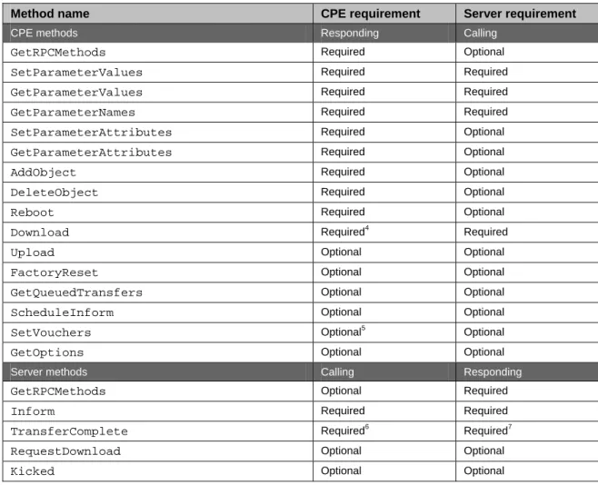
3.6 RPC Support Requirements
Table 4 provides a summary of all methods, and indicates the conditions under which implementation of
each RPC method defined in Appendix A is REQUIRED or OPTIONAL.
Table 4 – RPC message requirements
Method name
CPE requirement
Server requirement
CPE methods Responding Calling
GetRPCMethods
Required OptionalSetParameterValues
Required RequiredGetParameterValues
Required RequiredGetParameterNames
Required RequiredSetParameterAttributes
Required OptionalGetParameterAttributes
Required OptionalAddObject
Required OptionalDeleteObject
Required OptionalReboot
Required OptionalDownload
Required4 RequiredUpload
Optional OptionalFactoryReset
Optional OptionalGetQueuedTransfers
Optional OptionalScheduleInform
Optional OptionalSetVouchers
Optional5 OptionalGetOptions
Optional OptionalServer methods Calling Responding
GetRPCMethods
Optional RequiredInform
Required RequiredTransferComplete
Required6 Required7RequestDownload
Optional OptionalKicked
Optional Optional3.7 Transaction Session Procedures
All transaction sessions MUST begin with an Inform message from the CPE contained in the initial HTTP
post. This serves to initiate the set of transactions and communicate the limitations of the CPE with regard
to message encoding.
4
Required only if file downloads of any type are supported.
5The session ceases when both the ACS and CPE have no more requests to send, no responses remain due
from either the ACS or the CPE. At such time, the CPE may close the connection.
No more than one transaction session between a CPE and its associated ACS may exist at a time.
Note – a transaction session is intended to persist only as long as there are messages to be
transferred in either direction. A session and its associated TCP connection are not intended to
be held open after a specific exchange of information completes.
3.7.1 CPE
Operation
3.7.1.1 Session
Initiation
The CPE will initiate a transaction session to the ACS as a result of the conditions listed in section 3.2.1.
Once the connection to the ACS is successfully established, the CPE initiates a session by sending an initial
Inform request to the ACS. This indicates to the ACS the current status of the CPE and that the CPE is
ready to accept requests from the ACS.
In this initial HTTP post carrying the Inform request, only one SOAP envelope is allowed. The
MaxEnvelopes argument in the Inform response indicates the maximum number of envelopes that may be
carried by each subsequent HTTP post.
The CPE SHOULD initiate a session only when it has locked the Parameters accessible through this
interface to ensure they cannot be changed via any other mechanism. The CPE SHOULD maintain this
lock until the session is terminated.
3.7.1.2 Incoming
Requests
On reception of SOAP requests from the ACS, the CPE MUST respond to each request in the order they
were received, where order is defined as described in section 3.4.1. This definition of order places no
constraint on whether multiple responses are sent in a single HTTP post (if the ACS can accept more than
one envelope), or distributed over multiple HTTP posts.
To prevent deadlocks, the CPE MUST NOT hold off responding to an ACS request to wait for a response
from the ACS to an earlier CPE request.
3.7.1.3 Outgoing
Requests
When the CPE has request messages to send (after the initial Inform request), it may send these in any
order with respect to responses being sent by the CPE to the ACS. That is, the CPE may insert one or more
requests at any point in the sequence of envelopes it transmits to the ACS. There is no specified limit to the
number of requests a CPE may send prior to receiving responses (the number of outstanding requests). A
CPE MAY incorporate a locally specified limit if desired.
If the CPE receives an envelope from the ACS (either request or response) with the HoldRequests header
equal to true (see section 3.5), the CPE MUST NOT send any requests in subsequent HTTP posts. The
CPE may restart sending envelopes only when it subsequently receives an envelope with the HoldRequests
header equal to false (or equivalently, no HoldRequests header). In determining whether it may send a
request, the CPE MUST examine all envelopes received through the end of the most recent HTTP
response. Because of the envelope order defined in section 3.4.1, only the last envelope in an HTTP
response determines whether requests are allowed on the next HTTP post. If the CPE receives an empty
HTTP response from the ACS, this may be interpreted as HoldRequests equal false.
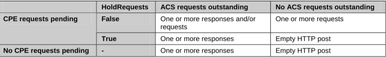
If there are one or more outstanding requests from the ACS, or if the CPE has one or more outstanding
requests and HoldRequests is false, then the CPE MUST send at least one request or response in any HTTP
post sent to the ACS. An empty HTTP post MUST be sent if the ACS has no requests or responses
outstanding. Table 5 lists the complete set of constraints on what a CPE MUST send while a session is in
progress.
Table 5 – CPE Message Transmission Constraints
HoldRequests ACS requests outstanding No ACS requests outstanding False One or more responses and/or
requests
One or more requests
CPE requests pending
True One or more responses Empty HTTP post
No CPE requests pending - One or more responses Empty HTTP post
3.7.1.4 Session
Termination
The CPE MUST terminate the transaction session when all of the following conditions are met:
1) The ACS has no further requests to send the CPE. The CPE concludes this if either one of the
following is true:
a) The most recent HTTP response from the ACS contains no envelopes.
b) The most recent envelope received from the ACS (in the order defined in section 3.4.1)
includes a NoMoreRequests header equal true (see section 3.5). Use of this header by a CPE
is OPTIONAL.
2) The CPE has no further requests to send to the ACS.
3) The CPE has received all outstanding response messages from the ACS.
4) The CPE has sent all outstanding response messages to the ACS resulting from prior requests.
The CPE MUST also terminate a session if it has received no HTTP response from an ACS for a locally
determined time period of not less than 30 seconds.
If the above conditions are not met, the CPE MUST continue the session.
If one or more messages exchanged during a session results in the CPE needing to reboot to complete the
requested operation, the CPE MUST wait until after the session has cleanly terminated based on the above
criteria before performing the reboot.
If the session terminates unexpectedly, the CPE SHOULD attempt to establish a new session, starting the
session establishment procedure from the beginning. The CPE MAY place locally specified limits on the
number of times it attempts to reestablish a session in this case.
3.7.2 ACS
Operation
3.7.2.1 Session
Initiation
Upon receiving the initial Inform request from the CPE, the ACS MUST respond with an Inform response.
The ACS may follow this with series of requests sent to the CPE.
The MaxEnvelopes argument in the Inform request indicates the maximum number of envelopes that may
be carried by each HTTP response sent by the ACS to the CPE. If the CPE can accept more than one
envelope, the initial HTTP response carrying the Inform response may also carry additional requests up to
the total limit imposed by MaxEnvelopes.
3.7.2.2 Incoming
Requests
On reception of SOAP requests from the CPE, the ACS MUST respond to each request in the order they
were received, where order is defined as described in section 3.4.1. This definition of order places no
constraint on whether multiple responses are sent in a single HTTP response (if the CPE can accept more
than one envelope), or distributed over multiple HTTP responses.
To prevent deadlocks, the ACS MUST NOT hold off responding to a CPE request to wait for a response
from the CPE to an earlier ACS request.
If the ACS wishes to prevent the CPE sending requests during some portion of the session, it may do so by
setting the HoldRequests header to true in each envelope transmitted to the CPE until the ACS again wishes
to allow requests from the CPE. The ACS MUST allow CPE requests before completion of a session (this
may be done either explicitly via the HoldRequests header or implicitly by sending an empty HTTP
response).
3.7.2.3 Outgoing
Requests
When the ACS has request messages to send, it may send these in any order with respect to responses being
sent by the ACS to the CPE. That is, the ACS may insert one or more requests at any point in the sequence
of envelopes it transmits to the ACS (after the Inform response). There is no specified limit to the number
of requests an ACS may send prior to receiving responses (the number of outstanding requests). An ACS
MAY incorporate a locally specified limit if desired.
If the ACS has one or more requests remaining to be sent and/or one or more responses outstanding from
earlier requests from the CPE, the ACS MUST send at least one request or response in any HTTP response
sent back to the CPE. An empty HTTP response is only allowed if the ACS has no more requests or
responses outstanding.
3.7.2.4 Session
Termination
Since the CPE is driving the HTTP connection to the ACS, only the CPE is responsible for connection
initiation and teardown.
The ACS may consider the session terminated when all of the following conditions are met:
1) The CPE has no further requests to send the ACS. The ACS concludes this if either one of the
following is true:
a) The most recent HTTP post from the CPE contains no envelopes.
b) The most recent envelope received from the CPE (in the order defined in section 3.4.1)
includes a NoMoreRequests header equal true (see section 3.5). Use of this header by an
ACS is OPTIONAL.
2) The ACS has no further requests to send the CPE.
3) The CPE has sent all outstanding response messages to the ACS resulting from prior requests.
4) The ACS has received all outstanding response messages from the CPE.
If the above criteria have not all been met, but the ACS has not received an HTTP post from a given CPE
within a locally defined timeout of not less than 30 seconds, it may consider the session terminated. In this
case, the ACS MAY attempt to reestablish a session by performing a Connection Request (see section
3.2.2).
3.7.3 Transaction
Examples
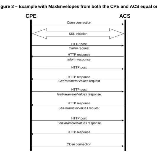
In the example shown in Figure 3, the ACS first reads a set of parameter values, and based on the result,
sets some parameter values. In the example show, MaxEnvelopes from both the CPE and ACS equal one,
so there is no pipelining of requests from the ACS, nor multiple responses per HTTP post from the CPE.
Figure 3 – Example with MaxEnvelopes from both the CPE and ACS equal one
CPE
ACS
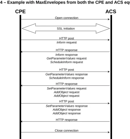
Open connection SSL initiation HTTP post HTTP response Informrequest Informresponse HTTP post GetParameterValuesresponse HTTP response SetParameterValuesrequest HTTP post SetParameterValuesresponse Close connection HTTP response HTTP post HTTP response GetParameterValuesrequestThe example in Figure 4 shows a scenario where MaxEnvelopes from both the CPE and ACS are equal to
three, allowing the use of message pipelining in both directions. In this example, some additional requests
from the ACS are shown.
Figure 4 – Example with MaxEnvelopes from both the CPE and ACS equal three
CPE
ACS
Open connection SSL initiation HTTP post HTTP response Informrequest Informresponse GetParameterValuesrequest ScheduleInformrequest HTTP post GetParameterValuesresponse ScheduleInformresponse HTTP response SetParameterValuesrequest AddObjectrequest AddObjectrequest HTTP post SetParameterValuesresponse AddObjectresponse AddObjectresponse Close connection HTTP responseNormative References
The following documents are referenced by this specification. Where the protocol defined in this
specification depends on a referenced document, support for all required components of the referenced
document is implied unless otherwise specified.
<