Selection of our books indexed in the Book Citation Index in Web of Science™ Core Collection (BKCI)
Interested in publishing with us?
Contact book.department@intechopen.com
Numbers displayed above are based on latest data collected. For more information visit www.intechopen.com Open access books available
Countries delivered to Contributors from top 500 universities International authors and editors
Our authors are among the
most cited scientists
Downloads
We are IntechOpen,
the world’s leading publisher of
Open Access books
Built by scientists, for scientists
12.2%
116,000
120M
TOP 1%
154
Biogas Plant Constructions
M. Samer
Cairo University, Faculty of Agriculture,
Department of Agricultural Engineering,
Egypt
1. Introduction
The chapter concerns with the constructions of the commercial biogas plants as well as the small and household units. Furthermore, the chapter aims at providing a clear description of the structures and constructions of the anaerobic digesters and the used building materials. Ultimately, the chapter answers an important question: how to build a commercial biogas plant and a household unit, and what are the construction steps?
2. Chapter description and contents overview
The chapter describes the construction steps and operation of biogas plant, which include:
a. Planning the biogas plant layout and designing the digesters, where the rules of thumb for planning the layout of a commercial biogas plant are elucidated and a methodology for specifying the dimensions of both digester(s) and residue storage tank(s) is illustrated, and they are: internal and external diameters of the tanks, wall thickness of the tank, height …etc.
b. Undertaking the project, i.e. carrying out the excavation (digging) works, preparation of the bottom plate of the digester, integrating the heating tubes, building the fermenter, installing the insulation, and technology installation.
c. Running the biogas plant including the mechanization of the biogas plant such as: solids feeder, gas processing unit, mixing technology …etc.
d. System control, i.e. how the individual facility components are monitored by computer technology even from afar as well as on-site using a computer system.
3. Overview
3.1 Components of the biogas unit
The components of a biogas unit are: 1. Reception tank
2. Digester or fermenter 3. Gas holder
3.2 Size of biogas unit
The size of a biogas unit depends on several factors, which are:
1. The amount and type of organic waste to be disposed in the digester
2. The objective of treating the organic waste (the production of energy and/or organic fertilizer)
3. Demand of natural gas and consumption pattern 4. On-site nature of the soil and the level of ground water
5. Air temperature in the region and wind direction throughout the different seasons 6. The training level of the staff on farm and home regarding operation of biogas units The amount of manure fed into a digester each day has an important effect on its operation. This is measured by volume added in relation to the volume of the digester, but the actual quantity fed to the digester also depends on the temperature at which the digester is maintained. In order to determine the unit size of a biogas unit, the following mathematical equation must be achieved:
Digester size (m³) = Daily feed-in (m³ day-1) × Retention time (day) (1)
The digester size can be defined as the total size of the biogas unit, which includes the effective size of any volume occupied by the fermented material and the volume of gas storage. Size of the daily feed-in is the size of a mixture of dung with water added to the digester once daily or several times and the average concentration of total solids of 10%, where mixing the organic wastes with water depends on its water content. In the case of wet animal wastes, such as manure the proportion of mixing is 1:1. Generally, Storage capacity has to be calculated by average live weight of animals kept in husbandry systems, amount of added water, periods of no fertilization of crops, and the animal species.
In order to plan a biogas plant and to design a digester, several design parameters must be determined which are: ratio of gathered waste from manure canals to total waste, number of cows in farm, amount of manure produced by a cow which is usually 1.8 m3 cow-1 month-1,
quantity of daily liquid organic matter deposition into the digester, hydraulic retention time, density and quantity of daily dry organic matter deposition into the digester, and digester load which is usually 2-4 kg m-3 day-1. The aforementioned design parameters are used to
determine the total volume of the materials that are intended to be stored in the tank and are equal to the internal volume of the tank. Additionally, the designer should take into consideration that a part of the tank (about 10%) is empty and the substrates should not fill it, because it is the place where the gas will accumulate. Even in case of designing other storage tanks (e.g. liquid organic matter tank) it is required to leave 10% of the tank volume empty.
3.3 Types of digester
During the last century a number of different types of flows in simple digester have been developed and they can be of the following kinds: (1) batch flow, (2) continuous flow, (3) continuously expanding, (4) plug flow, and (5) contact flow. The conventional digesters are those utilized to process liquid raw materials with a high content in solids, also called rural digesters, the fermentation chamber having a volume below 100 m3. Conventional digesters
are installed without any type of mechanism to reduce the retention time during which the biomass remains inside are predominant; these systems are fed discontinuously and known as discontinuous-flow i.e. batch digesters, or fed periodically and known as continuous-flow digesters.
Batch digesters are loaded at once, maintained closed for a convenient period, and the organic matter is fermented and then unloaded at a later time. It is quite a simple system with small operational requirements. Installation can be made in an anaerobic tank or in a series of tanks, depending on the biogas demand, availability and amount of raw materials to be utilized. Batch flow is most suitable for dry organic matters (solid materials), e.g. solid vegetable waste. This type of biowastes is fed into the digester as a single batch. The digester is opened, digestate is removed to be used as biofertilizer and the new batch replaces the digestate. The tank is then resealed and ready for operation. Depending on the waste material and the operating temperature, a batch digester will slowly start producing biogas and increase the production with time and then drop-off after 4 to 8 weeks. Batch digesters are therefore best operated in groups, so that at least one digester is always producing biogas.
Continuous digesters are usually requiring daily loading and residue management. The process is referred to as continuous since to every daily load corresponds a similar volume load of fermented material. The biomass inside the digester moves through by the difference in hydraulic heat, between the substrate entering the digester and the digestate coming out when unloading. Each load requires a retention time, usually between 14 to 40 days. Continuous digesters can have their retention period reduced by the introduction of agitation and heating. The disadvantage of these models is that the raw material needs to be diluted. The great advantage of these digesters over the batch type is that a single unit allows a continuous supply of biogas and biofertilizer and the continuous treatment of small amounts of waste (Florentino, 2003). Biogas production can be accelerated by continuously feeding the digester with small amounts of waste daily. If such a continuous feeding system is used, then it is essential to ensure that the digester is large enough to hold all the material that will be fed into the digester in the whole digestion cycle. One key issue is to implement two digesters, i.e. accomplishing the biodegradation of the organic waste through two stages, with the main part of the biogas is being produced in the first stage and the second stage serves as finishing stage of the digestion at a slower rate.
Regarding the continuously expanding flow, the digester starts one third full and then filled in stages and later emptied. Concerning the plug flow, the wastes are added regularly at one end and over-flows the other. In the contact flow, a support medium is provided.
Two simple biogas digester designs have been developed, the Chinese fixed dome digester and the Indian floating cover biogas digester. The digestion process is the same in both digesters but the gas collection method is different in each. In the Indian-type digester, the water sealed cover of the digester rises as gas is produced and acts as a storage chamber, whereas the Chinese-type digester has a lower gas storage capacity and requires efficient sealing in order to prevent gas leakage. Both have been designed for use with animal waste or dung. Additionally, there are also Philippine and Sri Lankan digesters.
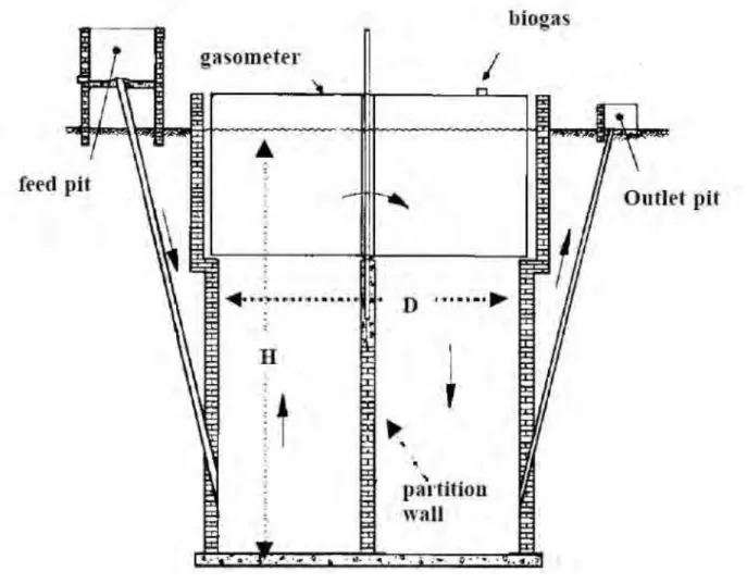
3.3.1 Indian digester
The Indian-type digester (Fig. 1) basically is comprised of a cylindrical body, gasometer, feed pit and outlet pit (Florentino, 2003). The digester is made using burnt-clay bricks and
cement. The cylindrical dome is made of metal sheets and moves up and down as it stores and releases the biogas. The digester is operated in continuing method and often vertically, almost cylindrical built. The putridity space filled the ground and it has a dividing wall. This dividing wall improves and holds back the fresh slime gush again through short way. The gas is gathered in floating gas lock. The steel gas lock is provided with stir elements. The periodic destruction of swimming layer is performed using the manual stirring of gas lock. The requested gas pressure arises from the heaviness of the swimming gas lock. The gas pressure can basically be changed in the practice by putting things on the gas lock. This type is suitable for the homogeneous materials, as for the animals’ excrements that do not tend to build sinking layers. The green waste must be split. If it is mixed with huge allotments, then it will threat the digester with blockage. Generally, there are several designs of Indian digesters, thereof: floating gas holder type biogas plant (KVIC model), Deenbandhu model, and Pragati model. The KVIC model is composite unit of a masonry digester and a metallic dome, where the maintenance of constant pressure by upward and downward movement of the gas holder. The Deenbandhu model consists of segments of two spheres of different diameters joined at their base, where this model requires lower costs in comparison to KVIC model. The Pragati model is a combination of Deenbandhu and KVIC designs, where the lower part of the digester is semi spherical with conical bottom and the floating drum acts as gas storage.
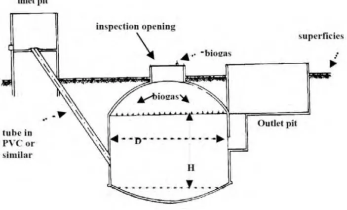
3.3.2 Chinese digester
The Chinese-type model digester (Fig. 2) is comprised of a cylindrical body, two spherical domes, inlet pit, outlet pit and an inspection opening (Florentino, 2003). The digester is made using cement and bricks and it is a permanent structure. Just as in the Indian digester this has two drains to feed waste and to collect the composted waste.
The biogas is collected in the upper chamber and the waste decomposes in the lower chamber. If the gas pressure exceeds the atmospheric pressure (1 bar) and there is no gas extracted from the dome, then the rot substrate squeezed from the reactor into the filled pipe, but often in the pool of counterpoise. If the produced gas is more than the up used gas, then the slime level will increase. If the up used gas is more than the produced gas during the gas extraction, then the slime level will sink and the rot slime will flow back. The volume of the counterpoise pool must be huge so that the repressed rot substrate can be digested at the highest gas volume. The gas pressure is not constant in the practice. It increases with the quantity of the stored gas. The gas must be regularly produced; therefore the gas pressure organizer or the swimming gas repository room is important.
Owing to the fact that the biogas dome digesters are completely buried underground, the fermentation temperature should be under a day/night temperature change, only in a tolerance range from about ± 2 ºC. The difference between summer and winter is large and is subject to the climate zone. The biogas dome digester can be provided with stir. In small family household units, a mix concoction for the biogas dome digester is installed. Different building and construction forms of biogas dome digesters were proved for the Chinese digesters; so that there is a big number of building methods are used.
3.4 Designs of digester
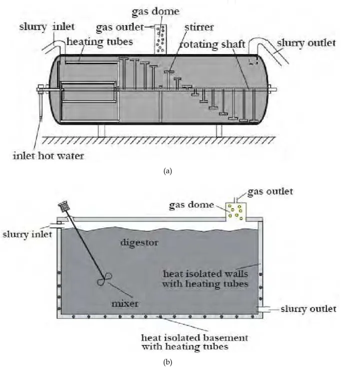
The most common digester design is cylindrical. Digesters can be classified in horizontal and vertical designs (Fig. 3). Currently, vertical concrete or steel digesters with rotating propellers or immersion pumps for homogenization are widespread. Vertical tanks simply take feedstock in a pipe on one side, whilst digestate overflows through a pipe on the other side. In horizontal plug-flow systems, a more solid feedstock is used as a plug that flows through a horizontal digester at the rate it is fed-in. Vertical tanks are simpler and cheaper to operate, but the feedstock may not reside in the digester for the optimum period of time. Horizontal tanks are more expensive to build and operate, but the feedstock will neither leave the digester too early nor stay inside the digester for an uneconomically long period.
(a)
(b)
Anaerobic digesters can be built either above or under the ground. An alternative is that a part of the digester can be buried. Anaerobic digesters constructed above ground are steel structures to withstand the pressure; therefore, it is simpler and cheaper to build the digester underground. Maintenance is, however, much simpler for digesters built above ground and a black coating will help provide some solar heating.
4. Building materials and dimensions
Reinforced concrete is obtained by adequately mixing specific proportions of aggregates (gravels and sand), cement, and water (Bartali, 1999). The water:cement ratio is 0.53 L kg-1
and the cement:sand:gravel mass ratio is 1:2.2:3.7 for floors, driveways, structural beams, and columns (Lindley & Whitaker, 1996). Cylindrical cast-in-place concrete tanks are commonly used in biogas plants for storing liquid manure during long periods. A serviceable tank should be watertight to prevent groundwater pollution and corrosion of the reinforcing rods. Therefore, these tanks should be designed to withstand different design loads, i.e. the loads of the soil outside the digester which is buried underground level and loads of the liquid stored inside the digester. Liquid manure is often stored in large cylindrical concrete tanks, which are partially underground. The dimensions of these tanks vary from 18 to 33 m in diameter with heights from 2.4 to 4.9 m and a uniform wall thickness varying from 150 to 200 mm (Ghafoori & Flynn, 2007; Godbout et al., 2003).
The internal volume of the tank can be calculated by multiplying the volume of substrates that should be stored in the tank by 1.10 in order to consider 10% as headspace. The cement mass (kg), gravels volume (m3), and sand volume (m3) required to build the tank can be calculated
by multiplying the concrete volume of the tank by the constants C, G, and S, respectively, where C represents the mass of cement required to make 1 m3 of concrete (325 kg m-3), G is the
volume of gravel required for 1 m3 concrete (0.8 m3 of gravel per m-3 of concrete), and S is the
volume of sand required for 1 m3 concrete (0.4 m3 of sand per m-3 of concrete). The type of iron
rods should be selected. The different types (NØD m-1, where N is the number of iron rods per
meter length, and D is the diameter of the iron rod) are 6Ø6 m-1 (0.666 kg m-1) and 6Ø8 m-1
(0.888 kg m-1). In the case of constructing a tank without a concrete top, both types can be used.
On the other side, in the case of building a tank with a concrete top, the type 6Ø8 m-1 must be
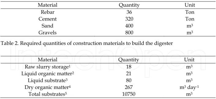
used with two iron grids (Samer, 2008, 2010, 2011; Samer et al., 2008). The thickness of digester wall should be 35 cm and is built using reinforced concrete to bear the loads of the materials stored in the digester. Tables 1 through 3 show the typical digester specifications for a commercial biogas plant, the required quantities of construction materials to build the digester, and the quantities of the substrates.
Specification Value Unit
Internal diameter of the digester 23 m External diameter of the digester 23.7 m Internal height of the digester 6 m
Buried part of the digester 2 m
Wall thickness of the digester 0.30 m
Capacity 11820 m3
Material Quantity Unit
Rebar 36 Ton
Cement 320 Ton
Sand 400 m3
Gravels 800 m3
Table 2. Required quantities of construction materials to build the digester
Material Quantity Unit
Raw slurry storage1 18 m3
Liquid organic matter2 21 m3
Liquid substrate3 80 m3
Dry organic matter4 267 m3 day-1
Total substrates5 10750 m3
1Consider a duration of 3 days for mixing and pumping, daily manure deposition of 6 m3 day-1, 1.8 m3
cow-1 month-1, and 100 cows
2Consider a storage duration of 7 days and liquid organic matter deposition of 3 m3 day-1 3Consider 40 days of storage duration and liquid substrate deposition of 2 m3 day-1 4Consider digester load of 4 kg m3 day-1 and density of 1.2 kg m-3
5Total quantity of substrates (10750 m3) that should be stored in a digester having a capacity
of 11820 m3
Table 3. Quantities of the substrates
5. Construction steps
5.1 Facility layout
The anaerobic digestion can be accomplished in one digester, and thus the facility is called ‘single-stage biogas facility’. In other facility layouts, the anaerobic digestion can be carried out in two stages, i.e. in two different tanks in order to optimize the operating conditions, and thus the facility is called ‘two-stage biogas facility’. The single-stage facility is a simple design with a longer track record, and has lower capital costs and technical problems. The two-stage facility has shorter retention time as each stage design is optimized. There is a potentially higher biogas production from two-stage facilities, but they require higher capital costs.
Subsequent to the site investigations such as the soil specifications ground water level, the facility layout should be planned. The commercial biogas plants consists of a fermenter and a secondary fermenter or so called “follow-up fermenter”, where both have identical dimensions, usually as follows: height of 6 m, internal diameter of 23 m, and external diameter of 23.70 m. This implies that the thickness of the fermenter wall is usually 35 cm. A residue storage tank is annexed to the fermenters, where the tank has an internal diameter of 25 m, external diameter of 25.70 m and a height of 6 m (Fig. 4). The solids feeder is located adjacent to the fermenter, and the tanks are surrounded by green belt from all sides except one side where the horizontal silos are located.
(a) MT-ENERGIE GmbH & Co. KG
(b) General process scheme of the two-stage anaerobic digestion process (Blumensaat and Keller, 2005)
(c) BIOGAS NORD GmbH Fig. 4. Facility layout for a two-stage biogas plant
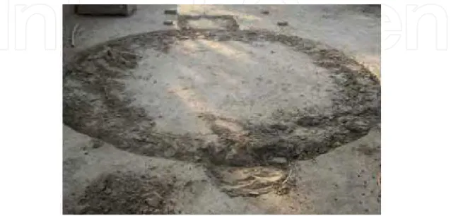
5.2 Dimensions marking
The marking of dimensions (Fig. 5) for biodigester unit should be performed prior to start of excavation work. The marking is considered as preparation for excavation and construction works. An operational area of 3 m width around the digester should be considered, where the workers will use this area to achieve the construction works around the tank base in order to prepare the structure of the concrete base, i.e. the bottom of the digester.
Fig. 5. Marking of dimensions for a biodigester
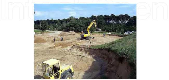
5.3 Excavation works
The depth of digging depends on the specifications of the soil. The inclination of the sides should be 30 cm for each meter depth for the cohesive soil, 60 cm to one meter for the light soil, and 90 cm for the sandy soil.
(a, b) BIOGAS PLANT DESIGN Fig. 6. Excavation works for household units
The bottom of the pit should be concave, where the center of the digester should be the most concave. Generally, the pit shape depends on the design of the digester, where in the case of round-shaped household units (Figs. 6a and b) a guide wood post is installed in the center of pit bottom. A string is linked to the post and used to set the round-shape of the pit. On the other hand, in the case of commercial biogas plants (Fig. 7), total station, teodolit or laser leveling is used for surveying. For large digesters, i.e. for commercial biogas plants, bulldozers are used to achieve the excavation (Fig. 7).
Fig. 7. Excavation works for a commercial biogas plant
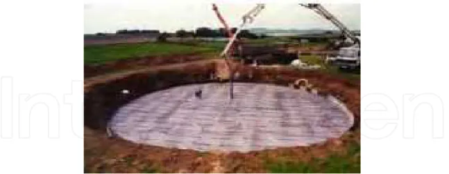
5.4 Preparation of the digester’s bottom
The pit’s bottom should be cleaned, and the gridiron is built (Fig. 8) using a pre-selected type of iron rods as either 6Ø6 m-1 or 6Ø8 m-1. Subsequently, the concrete mixture is poured
(Fig. 9 and 10). The water:cement ratio is 0.53 L kg-1 and the cement:sand:gravel mass ratio is
1:2.2:3.7. The thickness of the concrete base ranges between 10-25 cm depending on the soil’s specifications and the ground water level.
Fig. 9. Pouring the concrete mixture for a commercial biogas plant (BIOGAS NORD GmbH)
Fig. 10. Concrete bottom of a household unit
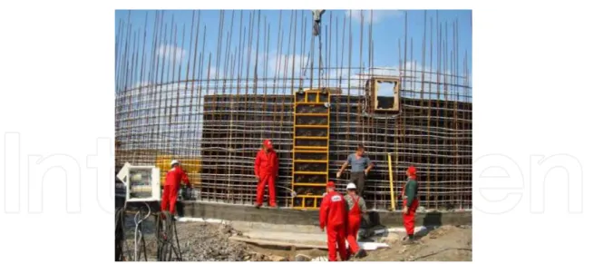
5.5 Building the digester
In case of commercial biogas plants, the digester is huge as its diameter may reach 25 m; therefore, the concrete structure should be reinforced (Fig. 11). Hence, the iron rods are used to build 2 iron grids to reinforce the digester wall starting from the digester bottom plate. The standard length of iron rods is 12 m. The standard iron rods are cut to shorter iron rods, and they are then used to build up the tank. Subsequently, either wood panels or pre-constructed metal sheets are used to enclose the iron grids and to form a container for the fluid concrete. When the digester wall is built, about one third of the internal wall of the tank is covered by a protection layer in order to protect the internal face of the wall against corrosion.
Fig. 11. Building the digester wall for a commercial biogas plant
In case of household units, burnt-clay bricks are used to build the digester (Fig. 12) and they should be able to tolerate a pressure up to 100 kg cm-2 owing to the fact that the walls of the
digester are exposed to the pressures of the soil and the moving equipment near to the digester. A mortar of cement and sand mixture by 1:4 is used. The construction works are followed up till the appropriate height, and the entry or exit holes of the pipes are blocked by a filling material.
Fig. 12. Building the digester wall of a household unit using burnt-clay bricks
5.6 Integrating the heating tubes
Building the digester is associated with integrating the heating tubes. Building the wall starts with structuring the iron grids which will be encased by wood panels or pre-constructed metal sheets, and before pouring the concrete, the heating tubes should be integrated (Figs. 11 and 13). The heating tubes are made of polyvinyl chloride (PVC), inside these tubes hot water flows to heat the digester. The water temperature is either 35 oC or 55 oC depending on the used bacteria as either mesophilic of thermophilic bacteria,
respectively. On the other hand, in other designs the heating tubes are installed on the internal surface area of the digester wall.
Fig. 13. Integrating the heating tubes (BIOGAS NORD GmbH)
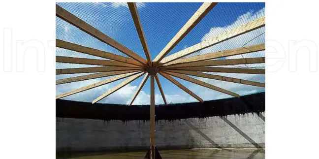
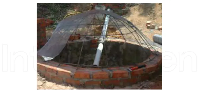
5.7 Building the gas holder
A wood or steel structure in form of umbrella is built, and then a mesh network is relayed on the umbrella structure (Figs. 14 and 15). The air supported double membrane cover, which includes the gas holder, is mounted over the structure. The flexible membrane of the gas collector, i.e. holder, moves up and down as a function of the gas pressure. On the other hand, the storage tank covers are numerous: (1) closed cover (concrete, plastic, and tent), (2) straw cover, (3) granulate (perlite), (4) swimming vinyl covering, and (5) open as open lagoons and open storage tanks.
Fig. 14. Wood structure and mesh network that supports the gas holder of digester in a commercial biogas plant (MT-ENERGIE GmbH & Co. KG)
Fig. 15. Mesh network that supports the gas holder of a household unit
5.8 Technology installation
The technology that should be installed includes the filling indicator, tubes, measuring devices and meters, electricity network, fiber cables …etc. Afterwards, the gas collector should be installed as well as the excess and low pressure safeguard and the air support fan. Figure 16 shows an overview of the technology installation.
(a) MT-ENERGIE GmbH & Co. KG (b) BIOGAS NORD GmbH Fig. 16. Technology installation
5.9 Installing the insulation
This is the process of lining the digester by mortar or using sheets of foam as in Figure 17. This is one of the most important construction steps and should be carefully and accurately achieved. In case of lining, the process is performed using mortar containing 1% silica. After the completion of the lining, the digester is painted using the petroleum Albumen. In other designs, the walls are heat insulated with a clad with non-corroding and weather-proof aluminum trapezoidal panels. On the other hand, the rural digesters are coated with layers of dry dirt and asbestos.
Fig. 17. Installing the insulation (BIOGAS NORD GmbH)
6. Information technology and mechanization
6.1 Computer-aided design
A software was developed by Samer (2010) to plan and design biogas plants, specify the dimensions of the different tanks (raw slurry tank, liquid organic matter tank, digester tank, secondary digester tank, and residue storage tank), and compute the amounts of construction materials (iron rods, cement, sand, and gravel) required to build the concrete constructions. Furthermore, the software is able to calculate the capital investment and the fixed costs, the variable costs, and the total costs. Figure 18 shows the user interfaces of the input and output data windows.
(b) User interface for input data of digester tank
(c) User interface for output data
6.2 Gas processing unit
Chandrasekar (2006) demonstrated the gas processing unit (GPU). In stage one biogas from the digester will be cleaned of moisture droplets, particulates and hydrogen sulfide. The cleaned gas mixture, which consists primarily of methane (CH4) and carbon dioxide (CO2),
will be then converted in stage 2 to ultra-high purity hydrogen in a steam reformer. As a first step to realize this vision, a GPU was installed (Fig. 19) which has been successfully removing over 99% of hydrogen sulfide (H2S) along with most of the water droplets and
particulates. A steam reformer has been also installed.
Fig. 19. Activated carbon beds of the GPU (Chandrasekar, 2006)
In the GPU biogas from the digester is pressurized to over 3 inches water column by a blower. It then passes through a coalescing filter to remove most of the particulates and water droplets. Water collected in the coalescing filter gets automatically drained out once it reaches a certain level. The biogas is then heated to about 85 oF in a heater before it passes
through two successive activated carbon beds where H2S is converted into elemental sulfur.
The process has been optimized so that bed replacement is needed only once every six months. The configuration of dual beds allows for continuous operation even when one bed is being replaced. The bed manufacturer should be contracted to replace the used beds, thereby obviating the need for the farmer to handle the sulfur. The design requires minimum operation and maintenance and has been set up to be controlled through a computer that will also monitor the incoming gas pressure, control and monitor the blower as well as monitor the exit H2S concentration and shut the blower/GPU if the exit
concentration is greater than the set point. If the GPU shuts down, biogas will automatically feed the engine generator like before to produce electricity. A simple schematic of the GPU is shown in Figure 20.
Fig. 20. Schematic of the GPU (Chandrasekar, 2006)
6.3 Mixing technology
The types of mechanical mixing (Fig. 21) are: vertical mixing, horizontal mixing, and side mixing. Submersible motor mixing devices are usually used in commercial biogas plants. Each device is provided by a cable and gear protection system (Fig. 22). Light agitation increases the velocity of digestion, differently from heavy agitation which decreases the velocity of reaction. In digesters with capacities higher than 100 m3, it is necessary to install
equipment to provide agitation of the contents.
(a) Vertical mixing (b) Side mixing
(c) Horizontal mixing
(a) Submersible motor mixing devices (b) Cable and gear protection system
(c) Cable implementation to mixer Fig. 22. Gear protection system (MT-ENERGIE GmbH & Co. KG)
6.4 Solids feeder
The solids feeder (Fig. 23) is a device that feeds the digester by the solid biowastes, i.e. dry organic matter. The solids feeder consists of a dosing container, weighing cells, identification/weighing system, and a mechanical system. The mechanical system of the solids feeder consists of a hydraulic drive system for the pushing floor, cross feeder auger drive, transport auger drive, transport auger, tamping auger drive, and tamping auger.
(a)
(b)
6.5 Cover membrane
The cover membrane consists of a weather protection foil, gasholder membrane or gas collector, clamp hose, level indicator for the gas collector, excess and low-pressure safeguard, and a supporting structure (Fig. 24). A desulphurization unit is integrated into the inner membrane (gasholder) to reduce the hydrogen sulfide (H2S). The collector is sealed
gas-tight with two cone-shaped foils and a clamp rail.
There are three structure types for supporting the cover, which are: (1) a steel post supports directly the cover, (2) a wood structure (incl. a wood post) supports the cover, and (3) a steel post supports a wood structure which in turn supports the cover.
Fig. 24. Air supported double membrane cover (MT-ENERGIE GmbH & Co. KG)
6.6 Monitoring and controlling
The individual facility components are monitored by computer technology even from afar. At the same time technical procedures, as well as input and output quantities are neatly documented. The computer system consists of an on-site control system installed on a computer and sometimes another remote access system on another computer located far away from the site, e.g. in the company’s headquarter. The remote computer is connected to the site through routers (ISDN or DSL), allowing a remote control of the site. Any of the aforementioned computers is able control the biogas plant through controlling the central plant control system which is connected to the digester running components (agitator, pump, feeding system …etc.), the cogeneration unit, and the biogas analyzer. A control system allows for real-time local and remote operation and monitoring as well as data gathering (Fig. 25).
Fig. 25. Monitoring and controlling system (Environmental Power Corp.)
7. Running the biogas plant
Controlled fermentation of biomass in biogas plants produces a gas that can be used to produce electrical and thermal energy on account of its high percentage of methane. The raw materials used in biogas plants or their main substrates, are often liquid manure, agricultural products, and some agro-industrial wastes. The biogas plant may use silage maize as one of its renewable raw materials, with the aid of wheel loader, the maize is fed into either a storage bin or solids feeder, which takes a filling up approximately once a day. Silage maize is rich in energy, and on account of it is high degree of production it is very well suited for use in biogas firms. The storage bin is equipped by hydraulic flow discharger that continuously feed the maize onto a conveyor belt. A scale under the conveyor belt registers the weight of the maize silage. Liquid manure is the most important basic substrate used in biogas plants, after short influence storage in big tank, it is pumped through pipes directly into the blending pumps beside the maize conveyor belt, at the same time the maize fall off from the conveyor belt into separators, which is equipped with two mixing rollers, in this way the maize silage is mixed before fermentation. With this technology, it is possible to supply several fermentation tanks (also known as fermenters and digesters) with fresh substrates even if they are not close together. Liquid wastes from the food industry are the third substrates used in biogas plants, as the availability of such wastes varies considerably, a large storage pit should be installed to integrate this into a whole serving to minimize smells and help to prevent epidemics. The liquid waste is heated with hot water into 70 °C in a tubular heat exchanger using a counter current process. After heating for one hour, the hydrogenation of the substrate is complete so that they can be poured into the fermenters. The fermenter is the place where the biogas is formed, the substrate are continuously stirred in order to prevent layers of materials forming at the top or on the bottom, hot water tubes heat the substrates to between 35 and 55 oC to accelerate the formation of methane. The
substrate is in the fermenter for a period of around 30 days before it is filled into another fermenter for a further 30 days to complete the gas formation process. When fermentation is complete the thin liquid substrate is pumped into two reinforced concrete tanks, where it is stored until it can be brought out onto the fields.
7.1 Gas guidance
If the fermenters are filled regularly with biomass which is air-tight heated and regularly stirred, the biogas will be formed within a matter of days where the formation of biogas is a complex and delicate process. The organic fats which cover high rates contained in the substrates are digested by various kinds of bacteria, this is a starting point for the development of the gas, the contents are continuously stirred, the gas drives slowly to the top of the container and it consists of approximately 50 to 70% methane, carbon dioxide, water vapor, hydrogen, and hydrogen sulfide. As water vapor and hydrogen sulfide are problematic for the utilization of the gas maker, it is necessary to purify the biogas.
The gas is first cleaned from water vapor. The condensed water is collected and a condensation shaft pumps it out. On the other hand, the aggressive trace gas hydrogen sulfide is now extracted from the biogas in a biological desulfurization unit, by introducing air to the container certain bacteria culture which is able to establish colonies on chains. The bacteria decompose the hydrogen sulfide to harmless sulfa and water. The almost unpressurized biogas is then fed into a compressor where it is watered up to 70 mbar pressure later required for burning. In order to completely condense any reaming water vapor freeing biogas of any suspending matters, the biogas is subjected to a washing brine process, this is carried out at almost a freezing point, so that the gas is cooled down to a temperature of 5 degrees. In order to control the purification of the gas, the biogas is constantly tested with an online measuring system which records the amount of methane, hydrogen sulfide, and carbon dioxide. This guarantees a high degree of efficiency and security. In case of any over production of biogas, it is necessary to operate a gas flame for the unburned methane gas that escapes to the atmosphere which is harmful for the environment.
Using 15,000 tons of biomass per year, the plant produces a total of 500 kW of electricity and heat. The optimal gas processing engines can run several years with the minimum of maintenance costs. Up to 30% of the waste heats from the water cooling the engine is used in the heat exchanger and the fermenter so that no additional heat is required, the remaining heat can also be used profitably to heat industrial plants and houses. The electric power generated by the Combined Heat and Power Plant (CHP) is converted to high voltage and then the electricity can be fed into the grid who meets the annual requirement of around 1000 households.
7.2 Instrumentation and control
A biogas plant with an annual operating capacity of 15,000 tons a year requires 3-5 hours’ work daily in order to keep the amount of work gone to minimum with a particularly recommended use of an effective measurement of control technology. For safe exchange of data it is also possible for someone who is not on-site to monitor and control the unit, i.e. the unit can be remotely controlled. For example, the agitators can be switched on and off, and all the solid supply equipment can be monitored. Information about malfunctions can be registered on computer service or on the operator's mobile phone, these guarantees a short reaction time when anything unexpected happens.
Biogas plant produces high quality biofertilizers as well as electricity, the nutrients contained in the substrate are retained and more easily available to the plants, as the flow
power of the liquid manure and its ammoniacal content have increased, due to fermentation the unpleasant smell of liquid manure and organic wastes have disappeared, as the organic acids have been decomposed. The biogas plant is therefore useful for both the operators and their neighbors.
8. Conclusion
There is flexibility in the types of digester designs available. Digester types and designs are selected for the types of feedstocks to be digested. There are general approaches to tank design, mixing systems, and electrical generation systems. There are different construction quality approaches for household and farm-based in comparison to commercial digesters.
9. References
Bartali, E. (1999). Characteristics and Performances of Construction Materials, In: CIGR Handbook of Agricultural Engineering: Animal Production and Aquacultural Engineering, E. Bartali, A. Jongebreur, and D. Moffitt, (eds.), 3-29, ASAE, ISBN 0-929355-98-9, St. Joseph, Michigan, USA
Blumensaat, F. & Keller J. (2005). Modelling of Two-Stage Anaerobic Digestion Using the IWA Anaerobic Digestion Model No. 1 (ADM1). Water Research, Vol. 39, No. 1, pp. 171-183, ISSN 0043-1354
BIOGAS PLANT DESIGN. http://bio-gas-plant.blogspot.com/
BIOGAS NORD GmbH, Werningshof 2-4, 33719 Bielefeld, Germany. http://www.biogas-nord.com/
Chandrasekar, A. (2006). Demonstration of Hydrogen Production from Dairy Manure Derived Biogas, Proceedings of 2006 ASABE Annual International Meeting, Paper Number: 067065, Portland, Oregon, USA, July 9-12, 2006
Environmental Power Corp., 120 White Plains Rd, Tarrytown, NY 10591, USA. www.environmentalpower.com
Florentino, H. (2003). Mathematical Tool to Size Rural Digesters. Scientia Agricola, Vol. 60, No. 1, pp. 185-190, ISSN 0103-9016
Ghafoori, E. & Flynn P. C. (2007). Optimizing the Size of Anaerobic Digesters. Transactions of the ASABE, Vol. 50, No. 3, pp. 1029-1036, ISSN 2151-0032
Godbout, S.; Marquis, A.; Fafard, M. & Picard, A. (2003). Analytical Determination of Internal Forces in a Cylindrical Tank Wall from Soil, Liquid, and Vehicle Loads. Canadian Biosystems Engineering, Vol. 45, pp. 5.7-5.14, ISSN: 1492-9058
Gronauer, A. G. & Neser S. (2003). Concepts and Techniques for Sustainable Slurry Management on Farms, Proceedings of Ninth International Symposium on Animal, Agricultural and Food Processing Wastes, Paper Number: 701P1203, North Carolina, USA, October 12-15, 2003
Lindley, J. A. & Whitaker, J. H. (1996). Agricultural Buildings and Structures, ASAE, ISBN 0-929355-73-3, St. Joseph, Michigan, USA
MT-ENERGIE GmbH & Co. KG, Vor dem Seemoor 1, 27404 Rockstedt, Germany. http://www.mt-energie.com/
Samer, M. (2011). How to Construct Manure Storages and Handling Systems? IST Transactions of Biosystems and Agricultural Engineering, Vol. 1, No. 1, pp. 1-7, ISSN 1913-8741
Samer, M. (2010). A Software Program for Planning and Designing Biogas Plants.
Transactions of the ASABE, Vol. 53, No. 4, pp. 1277-1285, ISSN 2151-0032
Samer, M. (2008). An Expert System for Planning and Designing Dairy Farms in Hot Climates, Dissertation, VDI-MEG, ISSN 0931-6264, Script 472
Samer, M.; Grimm, H.; Hatem, M.; Doluschitz, R. & Jungbluth T. (2008). Mathematical Modeling and Spark Mapping for Construction of Aerobic Treatment Systems and their Manure Handling System, Proceedings of International Conference on Agricultural Engineering, Book of Abstracts p. 28, EurAgEng, Hersonissos, Crete, Greece, June 23-25, 2008
ISBN 978-953-51-0204-5 Hard cover, 408 pages
Publisher InTech
Published online 14, March, 2012
Published in print edition March, 2012
InTech Europe
University Campus STeP Ri Slavka Krautzeka 83/A 51000 Rijeka, Croatia Phone: +385 (51) 770 447 Fax: +385 (51) 686 166 www.intechopen.com
InTech China
Unit 405, Office Block, Hotel Equatorial Shanghai No.65, Yan An Road (West), Shanghai, 200040, China Phone: +86-21-62489820
Fax: +86-21-62489821
This book contains research on the chemistry of each step of biogas generation, along with engineering principles and practices, feasibility of biogas production in processing technologies, especially anaerobic digestion of waste and gas production system, its modeling, kinetics along with other associated aspects, utilization and purification of biogas, economy and energy issues, pipe design for biogas energy,
microbiological aspects, phyto-fermentation, biogas plant constructions, assessment of ecological potential, biogas generation from sludge, rheological characterization, etc.
How to reference
In order to correctly reference this scholarly work, feel free to copy and paste the following:
M. Samer (2012). Biogas Plant Constructions, Biogas, Dr. Sunil Kumar (Ed.), ISBN: 978-953-51-0204-5, InTech, Available from: http://www.intechopen.com/books/biogas/biogas-plant-constructions