Scratchpad Allocation for Concurrent Embedded Software
Vivy Suhendra, Abhik Roychoudhury, and Tulika Mitra
Department of Computer Science, National University of Singapore
{vivy, abhik, tulika}@comp.nus.edu.sg
ABSTRACT
Software-controlled scratchpad memory is increasingly employed in embedded systems as it offers better timing predictability com-pared to caches. Previous scratchpad allocation algorithms typi-cally consider single process applications. But embedded appli-cations are mostly multi-tasking with real-time constraints, where the scratchpad memory space has to be shared among interacting processes that may preempt each other. In this paper, we develop a novel dynamic scratchpad allocation technique that takes these process interferences into account to improve the performance and predictability of the memory system. We model the application as a Message Sequence Chart (MSC) to best capture the inter-process interactions. Our goal is to optimize the worst-case re-sponse time (WCRT) of the application through runtime reloading of the scratchpad memory content at appropriate execution points. We propose an iterative allocation algorithm that consists of two critical steps: (1) analyze the MSC along with the existing al-location to determine potential interference patterns, and (2) ex-ploit this interference information to tune the scratchpad reloading points and content so as to best improve the WCRT. We evaluate our memory allocation scheme on a real-world embedded applica-tion controlling an Unmanned Aerial Vehicle (UAV).
Categories and Subject Descriptors
C.3 [Special-purpose and Application-based Systems]: Real-time and embedded systems
General Terms
Design, PerformanceKeywords
Scratchpad memory, WCET, Message Sequence Chart
1.
INTRODUCTION
Scratchpad memory is a software-managed on-chip memory that has been widely accepted as an alternative to caches in real-time embedded systems, as it offers better timing predictability com-pared to caches. The compiler and/or the programmer explicitly
Permission to make digital or hard copies of all or part of this work for personal or classroom use is granted without fee provided that copies are not made or distributed for profit or commercial advantage and that copies bear this notice and the full citation on the first page. To copy otherwise, to republish, to post on servers or to redistribute to lists, requires prior specific permission and/or a fee.
CODES+ISSS’08,October 19–24, 2008, Atlanta, Georgia, USA. Copyright 2008 ACM 978-1-60558-470-6/08/10 ...$5.00.
controls the allocation of instructions and data to the scratchpad memory. Thus the latency of each memory access is completely predictable. However, this predictability is achieved at the cost of compiler support for content selection and runtime management.
In this paper, we address the problem of scratchpad memory allocation for concurrent embedded software (with real-time con-straints) running on uniprocessor or multiprocessor platforms.Our objective is to reduce the worst-case response time (WCRT) of the entire application. Our problem setting is representative of the current generation embedded applications (e.g., in automotive and avionics domain) that are inherently concurrent in nature and, at the same time, are expected to satisfy strict timing constraints. The combination of concurrency and real-time constraints introduces significant challenges to the allocation problem.
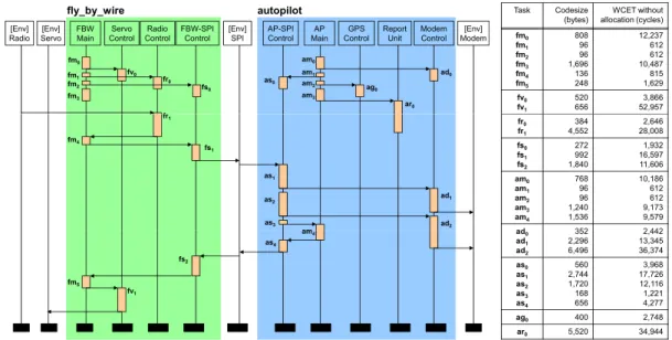
Given a sequential application, the problem of content selection for scratchpad memory has been studied extensively [9, 10, 12, 14]. However, these techniques are not directly applicable to concurrent applications with multiple interacting processes. Figure 1 shows a Message Sequence Chart (MSC) model [1, 3] depicting the inter-action among the processes in an embedded application. We use MSC model as it provides a visual but formal mechanism to cap-ture the inter-process interactions. Visually, an MSC consists of a number of interactingprocesseseach shown as a vertical line. Time flows from top to bottom along each process. A process in turn consists of one or moretasksrepresented as blocks along the vertical line. Message communications between the processes are shown as horizontal or downward sloping arrows. Semantically, an MSC denotes a labeled partial order of tasks. This partial order is the transitive closure of (a) the total order of the tasks in each pro-cess, and (b) the ordering imposed by message communications — a message is received after it is sent.
A naive allocation strategy can be to share the scratchpad mem-ory among all the tasks of all the processes throughout the lifetime of the application. Allocation algorithms proposed in the litera-ture for sequential applications can be easily adapted to support this strategy. However, this strategy is clearly sub-optimal, as a task executes for only a fraction of the application’s lifetime yet occupies its share of the memory space for the entire lifetime of the application. Instead, two tasks with disjoint lifetimes (e.g., tasks
fm0andfm4in Figure 1) should be able to use the same mem-ory space through time multiplexing. This is known asdynamic scratchpad allocationorscratchpad overlaywhere the scratchpad memory content can be replaced and reloaded at runtime.
As timing predictability is the main motivation behind the choice of scratchpad memory over caches, it should be maintained even in the presence of scratchpad overlay. This implies that in a concur-rent system (e.g., as shown in Figure 1),two taskst1andt2should be mapped to the same memory space only if we can guarantee
$3 0DLQ 0RGHP &RQWURO $363, &RQWURO *36 &RQWURO >(QY@ 0RGHP IO\BE\BZLUH 5HSRUW 8QLW )%: 0DLQ 6HUYR &RQWURO 5DGLR &RQWURO )%:63, &RQWURO >(QY@ 5DGLR >(QY@ 6HUYR >(QY@ 63, DXWRSLORW IP IP IP IP IY IU I IV DV DP DP DP DP DJ DU DG 7DVN &RGHVL]H
E\WHV DOORFDWLRQF\FOHV:&(7ZLWKRXW IP IP IP IP IP IP IY IY IP IU IV DV DV DV DP DG DG IU IU IV IV IV DP DP DP DP DP DG IV IP IY DV DP DG DG DG DV DV DV DV DV DJ DU
Figure 1: Message Sequence Chart (MSC) model of the adapted UAV control application
,QWHUIHUHQFH LPSURYHV" 7DVNOLIHWLPHV LQWHUIHUHQFH JUDSK 6FUDWFKSDG VKDULQJVFKHPH DOORFDWLRQ :&57 DQDO\VLV 6WRS 7DVN DQDO\VLV 6WDUW 6FUDWFKSDG DOORFDWLRQ GHFLVLRQ 7DVN:&(7V PHPRU\SURILOHV ,QLWLDOL]H HPSW\DOORFDWLRQ IXOOLQWHUIHUHQFH <HV 1R
Figure 2: Workflow of WCRT-optimizing scratchpad allocation
thatt1 andt2 have disjoint lifetimes. Otherwise,t1 andt2 may preempt each other, leading to scratchpad reloading delay at every preemption point. We can trivially identify certain tasks with dis-joint lifetimes; for example, based on the partial order of an MSC, if taskt1 “happens before" taskt2, clearlyt1 andt2have disjoint lifetimes. However, there may exist many pairs of tasks that are incomparable as per MSC partial order but still have disjoint life-times. Moreover, as scratchpad allocation reduces execution times of the individual tasks, the lifetimes and the interference among the tasks may change. Therefore, an effective scratchpad alloca-tion scheme attempting to minimize the WCRT of the applicaalloca-tion should consider the process interference as well as the impact of allocation on process interference.
In this paper, we propose aniterative allocation algorithm (Fig-ure 2) consisting of two critical steps: (1) analyze the MSC along with existing allocation to estimate the lifetimes of tasks and hence the non-interfering tasks, and (2) exploit this interference informa-tion to tune scratchpad reloading points and content so as to best improve the WCRT. The iterative nature of our algorithm enables us to handle the mutual dependence between allocation and process interaction. As we ensure a monotonic reduction of WCRT in every iteration, our allocation algorithm is guaranteed to terminate.
Concretely, our main contribution in this paper is a novel dy-namic scratchpad allocation technique that takes process interfer-ences into account to improve the performance and predictability of the memory system for concurrent embedded software. Our case study with a complex embedded application controlling an
Unmanned Aerial Vehicle (UAV) reveals that we can achieve sig-nificant performance improvement through appropriate content se-lection and runtime management of the scratchpad memory. Related Work
.
The problem of content selection for scratchpad memory has been studied extensively for sequential applications. Most of these works [10, 14] aim to minimize average-case exe-cution time or energy consumption through scratchpad allocation. Scratchpad content selection for minimizing the worst-case exe-cution time (WCET) has been addressed as well [9, 12]. How-ever, these techniques are not applicable when the scratchpad space needs to be shared among multiple interacting processes.The work by Verma et al. [15] presents a set of scratchpad shar-ing strategies among the processes for energy consumption mini-mization. However [15] simply assumes a statically defined sched-ule whereas we consider priority driven preemptive scheduling. Moreover, the scratchpad sharing decisions in [15] are not based on interactions and interference among the processes, which are critical in our case to provide real-time guarantees.
Scratchpad sharing among different processing elements (PEs) in a multiprocessor system-on-a-chip has also been investigated. Here the focus is more on mapping of codes/data to the private scratchpad memories of the PEs so as to maximize the benefit from the scratchpad allocation [4]. Other techniques include exploration of scratchpad hierarchy [2, 13] and runtime customization of scratch-pad sharing and allocation among the PEs [5].
Finally, this work complements the research on cache-related preempted delay (CRPD) [6, 7], which provides timing guarantee for concurrent software by analyzing interferences in cache mem-ory due to process interactions. Our work, on the other hand, elim-inates interference in memory through scratchpad allocation.
2.
PROBLEM FORMULATION
The input to our problem is in the form of Message Sequence Chart (MSC) [1, 3] that captures process interactions correspond-ing to a concurrent embedded application. We assume a preemp-tive, multi-taskingexecution model. The application is periodic in nature. The MSC represents interactions within one such invoca-tion where all processes involved should adhere to a common pe-riod and deadline. The underlying hardware platform contains one
IP IP IV IU IU IP : IP IP IV IU IU IP :¶ IP IP IV IU IU IP :
E%HIRUHDOORFDWLRQ F$OORFDWLRQEDVHGRQE G$IWHUDOORFDWLRQ H$IWHUDOORFDWLRQZLWKVODFN
: VFUDWFKSDGVSDFH )%: 0DLQ 5DGLR &RQWURO )%:63, &RQWURO IP IP IU D([WUDFWHG06& 7DVNOLIHWLPHV 7DVNOLIHWLPHV 7DVNOLIHWLPHV : : :¶ :¶ :¶ : : IP IU IV IP IV IU IU IP IP ,QWHUIHUHQFHJUDSK IP IV IU IU IP IP IP IV IU IU IP IP ,QWHUIHUHQFHJUDSK ,QWHUIHUHQFHJUDSK
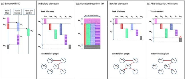
Figure 3: Sample MSC, task lifetimes and interference graphs before and after scratchpad allocation or more processing elements (PEs), each associated with a private
scratchpad memory. A process (a vertical line in the MSC) typi-cally corresponds to a specific functionality. It is thus natural to assign all the tasks in a process to one PE. The order in which the tasks appear on the process lifeline reflects their order of execution on the PE. In this paper, we assume zero communication delay be-tween processes. However, our analysis can be easily adapted to include non-zero communication delays.
Each process is assigned a unique static priority. The priority of a task is equal to the priority of the process it belongs to. A task
t1 in a processP may get preempted by a taskt2 from a higher priority processP. The assignment of static priorities to processes and the mapping of processes to PEs are inputs to our framework. Note that statically assigned priorities do not guarantee a fixed ex-ecution schedule at runtime. The preemptions and exex-ecution time variations depending on input lead to varying completion times of a task. This, in turn, gives rise to different execution schedules.
We now formalize the problem definition. Lett1, . . . , tNdenote the tasks belonging to all the processes in the application. Each taskti(1≤i≤N)is associated with a periodpi, a static priority
ri(the range ofriis[1, R]with 1 being the highest priority), and mapping to a PEP Ei(the range ofP Eiis[1, Q]whereQis the number of PEs in the system). As mentioned before, all the tasks belonging to a process have the same priority and are mapped to the same PE. Further, letci denote theuninterruptedworst-case execution time (WCET) of the tasktirunning onP Eiin isolation. The estimation ofci does not assume any scratchpad allocation, i.e., all the accesses incur the main memory latency.
LetSbe a particular scratchpad allocation for the application. In this work, we consider allocating program codes into the scratch-pad. The method applies similarly to data allocation. S consists of two components: (1) the amount of scratchpad spacespace(ti) allocated to each task, and (2) the allocation ofspace(ti)among the code blocks ofti. Note that as we allow scratchpad overlay, the same scratchpad memory space can be allocated to two or more tasks as long as they have disjoint lifetimes. LetMemidenote the set of all code blocks of ti available for allocation. Given
space(ti), the allocationAlloc(ti) ⊆ Memi is the set of most
profitable code blocks fromtito fit the capacity. Finally, WCET of
tias a result of allocationSis denoted aswcet(ti,S).
Given an allocationSand the corresponding WCET of the tasks, we can estimate thelifetimeof each task, defined as the interval
between the lower bound on the start time Start(ti,S) and the upper bound on the finish time F inish(ti,S) of the task. This estimation should take into account the dependencies among the tasks (total order among the tasks within a process and ordering imposed by message communication) as well as preemptions. The WCRT of the whole application is now given by
W CRT=max1≤i≤NF inish(ti,S)−min1≤i≤NStart(ti,S)
(1)
Our goal is to construct the scratchpad allocationSthat minimizes the WCRT of the application.
3.
METHOD OVERVIEW
Our proposed method is an iterative scheme (Figure 2), which we will elaborate below. Figure 3(a) shows an MSC extracted from our case study for the purpose of illustration.
Task Analysis
.
We analyze each task to determine its WCET with a given scratchpad allocation (initially empty), along with the area and the gain of allocating each of its code blocks. The WCET will serve as input to the WCRT analysis, while the memory profile will be used to choose the scratchpad content for the task at the alloca-tion step. We handle code allocaalloca-tion in this paper, for which possi-ble choices of granularity are a basic block (which we use here) or a function. The gain of allocating a block of code, in terms of execu-tion time saving, is the execuexecu-tion frequency of the block multiplied by the reduction in latency required to fetch the block from scratch-pad instead of from main memory. As we are considering systems with real-time constraints, the execution frequencies correspond to the worst-case execution path, which in turn is obtained via static analysis [11]. Worst-case execution path may shift as allocation de-cisions change; thus task profiles should be updated following each change in the course of the iterative improvement. We adapt our previous work on WCET-centric allocation of data for a single task to scratchpad memory [12] for this purpose.WCRT Analysis
.
The WCRT of a tasktiis a function of its WCET value and the delay caused by higher priority tasks whose lifetimes overlap with that ofti. A fixed-point iteration computes this value by finding the root to the equationx=g(x) =wcet(ti,S) + X
tj∈intf(ti)
intf(ti) =˘tj˛˛rj< ri AND (2)
ˆStart
(tj,S), F inish(tj,S)˜∩ˆStart(ti,S), F inish(ti,S)˜=∅¯
If we denote this WCRT value aswcrt(ti,S), we have for each taskti:F inish(ti,S) =Start(ti,S) +wcrt(ti,S). Further, the partial ordering of tasks in the MSC imposes the constraint that a tasktican start execution only after all its predecessors have com-pleted execution. In other words,Start(ti,S) ≥ F inish(u,S) for all tasksuprecedingtiin the partial order of the MSC. Ob-serving these rules, the WCRT analysis computes the lifetimes of all tasks in all processes. After the analysis, we construct thetask interference graphfor the purpose of scratchpad allocation. Figure 3(b) shows the task lifetimes computed by the WCRT analysis and the constructed interference graph given the MSC in (a). An edge between two nodes in the interference graph implies overlapping lifetimes of the two tasks represented by the nodes.
Scratchpad Sharing Scheme & Allocation
.
Based on the inter-ference pattern resulting from the WCRT analysis, we can construct a scratchpad sharing scheme among tasks on the same PE. One pos-sible scheme is illustrated in Figure 3(c), which shows the space sharing among tasks as well as the dynamic overlay over time. The schemes will be elaborated in the next section. The sharing scheme determines the space allocated to each task, and the memory pro-files obtained in the first step are used to select the most beneficial scratchpad content. The selection strategy is based on our previous work that aims to minimize the task WCET, taking into account the possible shift in worst-case execution path [12]. After allocation is performed, the task analysis is re-applied to find the new WCET. Post-Allocation Analysis.
Given updated task WCETs after al-location, the WCRT analysis is performed once again to compute updated task lifetimes. There is an important constraint to be ob-served in the WCRT analysis when the allocation decision has been made. The new WCET values have been computed based on the current scratchpad allocation, which is in turn decided based on the task interference pattern resulting from the previous analysis. In particular, scratchpad overlays have been decided among tasks de-termined to be interference-free. Therefore, these values are only valid for the same interference pattern, or for patterns with less in-terference. To understand this, suppose the interference graph in Figure 3(b) leads to the allocation decision in (c). The reduction in WCET due to the allocation in turn reduces task response times and changes task lifetimes to the one shown in (d). However, this computation of lifetimes is incorrect, because it assumes the WCET value offs0given that it can occupy the assigned scratchpad space throughout its execution. Iffm4is allowed to start earlier, right af-ter its predecessorfr1as shown in (d), it may in fact preemptfs0, flushing the scratchpad content offs0and causing additional delay for reload whenfs0resumes. Indeed, we see that the interference graph in (d) has an added edge fromfm4tofs0.To avoid this unsafe assumption, we need to maintain that tasks known not to interfere when allocation decision is made will not become interfering in the updated lifetimes. This is accomplished by introducingslack that forces the latter task to “wait out” the conflicting time window. The adapted WCRT analysis consults existing interference graph and adjustsStart(fm4,S) such that
Start(fm4,S) ≥ F inish(fs0,S). Figure 3(e) shows the
ad-justed schedule, which maintains the same interference graph as (a) by forcingfm4to start afterfs0has completed.
With a more sophisticated sharing/allocation scheme and sched-ule adjustment as we will introduce next, we can sometimes re-move existing task interferences without adding interference else-where. When this happens, we iterate over the allocation and
anal-fm1 fm2 fs0 fr0 fr1 fm4
(a) Profile-based Knapsack (PK) (b) Interference Clustering (IC)
tim e scratchpad space scratchpad space fm1 fm2 fs0 fr0 fr1 fm4 tim e
(c) Graph Coloring (GC) (d) Critical Path Interference Reduction (CR)
scratchpad space tim e fm1 fm2 fs0 fr0 fr1 fm4 scratchpad space tim e fm1 fm2 fs0 fr0 fr1 fm4
Figure 4: PK, IC, GC, and CR allocation schemes ysis steps to enhance current decision, until no more improvement can be made (Figure 2). As task interferences are enforced to be non-increasing, the iteration is guaranteed to terminate.
4.
ALLOCATION METHODS
This section describes the scratchpad allocation routine, which is the focus of our paper.
As only one task will be running on the PE at any given time, we can actually utilize the whole scratchpad space for the single executing task. The concern arises when a task is preempted, as flushing the scratchpad content will cause additional reloading de-lay when the task resumes. In that case, it may be beneficial to reserve a portion of the scratchpad for each of the tasks ( space-sharing), thus avoiding the need to flush and reload the scratchpad memory at each preemption/resume. On the other hand, two tasks guaranteed to never interfere with each other can share the same space via overlay (time-sharing). In Figure 3(b), tasksfm2and
fr0are space-sharing tasks, while taskfm1 in time windowW1 has a time-sharing relationship with all tasks in time windowW2.
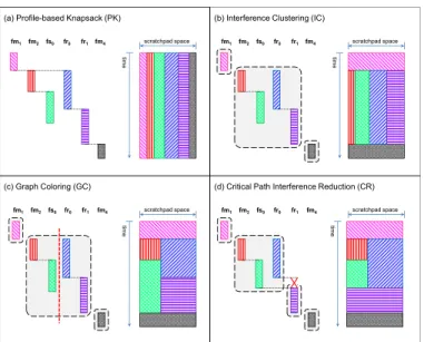
The various schemes are illustrated in Figure 4. The left side of each picture shows task lifetimes as determined by the WCRT anal-ysis, and the right side sketches the state of the scratchpad memory due to the different allocation schemes. For the purpose of compar-ing the scratchpad state, the lifetime of each task has been drawn with the same height across the different schemes (with the excep-tion ofCR). In reality, the heights (representing the length of task runtime) will vary due to the different allocation decisions. Profile-based Knapsack (PK)
.
As the baseline method, we con-sider a profile-based static allocation method. In this scheme, all tasks executing on the same PE will share the PE’s scratchpad space throughout application lifetime. The allocation decision does not consider the possible interferences (or lack thereof) within the PE.Partitioning and scratchpad allocation for each PEqcan be si-multaneously optimized via an Integer Linear Programming (ILP) formulation. The objective is to minimize the combined WCET weighted by task periods, defined as
X ti:P Ei=q wcet(ti,S)‹pi wcet(ti,S) = ci− X b∈Alloc(ti) freqb×areab×Δ
Recall thatci is the running time oftiwhen all code blocks are fetched from the main memory, andAlloc(ti) ⊆ Memi is the selected set of code blocks oftiin scratchpad allocationS.freqb andareab are respectively the execution frequency in the worst-case path and the area occupied by blockb. The termΔdefines the savings in execution time per unit area due to the scratchpad allocation. Given the scratchpad size ofcapqattached to PEq, the capacity constraint is expressed as0
@ X ti:P Ei=q X b∈Alloc(ti) areab 1 A≤capq
For allocation of program code into the scratchpad, an additional constraint is needed to maintain correct control flow [10]. If two se-quential basic blocks are allocated in different memory areas (i.e. one in scratchpad and one in main memory), then a jump instruc-tion should be inserted at the end of the earlier block.
Figure 4(a) shows the partitioned scratchpad byPK. As the allo-cation decision does not depend on task interference,PKwill only execute for one round; no iterative improvement can be made. Interference Clustering (IC)
.
In this second method, we use task lifetimes determined by the WCRT analysis to forminterference clusters. Tasks whose lifetimes overlap at some point are grouped into the same cluster. They will share the scratchpad for the entire duration of the common time window, from the earliest start time to the latest finish time among all tasks in the cluster. The same partitioning/allocation routine used inPKis employed among all tasks in the same cluster. The left part of Figure 4(b) shows the clustering decision for the given task schedule. fm1 as well asfm4have been identified as having no interference from any other task. Each of them is placed in a singleton cluster and enjoys the whole scratchpad space during its lifetime.
Graph Coloring (GC)
.
TheICmethod is prone to produce large clusters due to transitivity. In Figure 4(b), even thoughfm2 andfs0 do not interfere with each other, their independent interfer-ences withfr0end up placing them in the same cluster. Because of this, simply clustering the tasks will likely result in inefficient deci-sions. The third method attempts to enhance the allocation within the clusters formed by theICmethod by making use of the task-to-task interference relations captured in the interference graph. If we applygraph coloringto this graph, the resulting colors will give us groups of tasks that do not interfere with each other within the cluster. Tasks assigned to the same color have disjoint lifetimes, therefore can reuse the same scratchpad space via further overlay.
Graph coloring using the minimum number of colors is known to be NP-Complete. We employ the Welsh-Powell algorithm [16], a heuristic method that assigns the first available color to a node, without restricting the number of colors to use. Given the interfer-ence graph, the algorithm can be outlined as follows.
1. Initialize all nodes to uncolored.
2. Traverse the nodes indecreasing order of degree, assigning color 1 to a node if it is uncolored and no adjacent node has been assigned color 1.
3. Repeat step 2 with colors 2, 3, etc. until no node is uncolored. After we obtain the color assignment, we formulate the scratchpad partitioning/allocation with the refined constraint that a tasktiwith assigned colorkican occupy at most the space allocated forki, denoted byarea(ki). The scratchpad space given to allKcolors used for PEqadd up to the total capacitycapq, as expressed below.
X b∈Alloc(ti) areab≤area(ki); K X k=1 area(ki)≤capq
Figure 4(c) shows the further partitioning within the second clus-ter formed byIC.fm2andfs0have been assigned the same color, and allocated the same partition of the scratchpad to occupy at dif-ferent time windows. The similar decision applies tofr0andfr1. The partition will be reloaded with the relevant task content when execution transfers from one task to another.
1 repeat
2 CT :=∅;
3 foreachtaskton the critical path of current scheduledo
4 CT :=CT∪ {(t, u)|u∈intf(t)};
5 /*intf(t): the set of higher priority tasks whose lifetimes overlap witht’s (Equation 2) */
6 ifCT=∅then
7 Find any(tm, um)inCTsuch that
wcet(um,S)≥wcet(u,S)for all pairs(_, u)inCT;
8 /*eliminate this interference by imposing slack*/
9 Set constraintStart(tm,S)≥F inish(um,S); 10 Run WCRT analysis to propagate lifetime shift;
untilCT =∅;
Algorithm 1:The CR algorithm
Critical Path Interference Reduction (CR)
.
While the above three schemes try to make the best out of the given interference pattern, the final method that we propose turns the focus to reducing the interference instead. This is motivated by the observation that al-location decisions are often compromised by heavy interference. When the analysis recognizes a potential preemption of one task by another, both tasks will have to do space-sharing; in addition, the lifetime window of the preempted task must make allowance for the time spent waiting for the preempting task to complete. In an extreme case, if a taskt1is released right before a higher prior-ity taskt2, it must wait for practically the entire execution duration oft2. In this case, suppressing the release time oft1untilt2 com-pletes can only be beneficial:t1’s waiting time is still the same, yet no preemption cost is incurred, and a better allocation decision can be made for both tasks. In general, this is a good strategy when the waiting time far outweighs the actual computation time of the task. The method proceeds as shown in Algorithm 1. We first work on the schedule produced by the WCRT analysis to improve the in-terference pattern. In choosing which inin-terference to eliminate, we naturally look at the critical path of the application, as determined by the WCRT analysis. We consider all interferences in which tasks on the critical path are preempted or have to wait for tasks with higher priority (line 4). From these, we choose the interfer-ence that occupies the longest time window, that is, one in which the higher-priority task has the longest WCET (line 7). We elimi-nate this interference by forcing a delayed start time for the affected task (line 9), then propagate the shift to all tasks by re-running the WCRT analysis. Certainly, new interferences are not allowed to arise in this step. From the new schedule, we again consider pre-emptions on the critical path, which may or may not have shifted. The elimination and re-analysis are iterated until no more interfer-ences can be eliminated from the critical path. We then proceed to perform scratchpad partitioning/allocation as in theGCscheme on this improved interference graph. In Figure 4(d), the interference betweenfs0andfr1has been eliminated by lettingfr1 wait out the lifetime offs0 instead of starting immediately after the com-pletion of its predecessorfr0. This improvement freesfr1 from all interference. It can now occupy the whole scratchpad memory throughout its lifetime.% .% .% .% .% :& 5 7 . F\ FOHV 6FUDWFKSDGFRQILJXUDWLRQ 3( 3. ,& *& &5 .F\ FO HV 3( 3. ,&
3. ,& *& &5 [% [ % 3. ,& *& &5 % .% .% .% .% $OJRULWKPUXQWLPHVHFRQGV $OJRULWKPUXQWLPHVHFRQGV [% [% [.% [.% [.% :& 5 7 6FUDWFKSDGFRQILJXUDWLRQ *& &5 [% [% [% [.% [.% :&57 .F\ FO HV 6FUDWFKSDGFRQILJXUDWLRQ 3( 3. ,& *& &5 [% [.% [.% [.%
3. ,& *& &5 [% [ % [ % [ .% [ .% $OJRULWKPUXQWLPHVHFRQGV
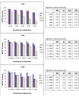
Figure 5: WCRT of the benchmark application after allocation by PK, IC, GC, and CR, along with algorithm runtime
5.
EXPERIMENTS AND DISCUSSION
We use as case study the UAV control application from PapaBench [8], adapted into a distributed implementation. The controller con-sists of two main functional units (fly_by_wire,autopilot) and operates in one of two modes: manual and automated. Figure 1 shows the active processes in one of the scenarios under the man-ual mode. The original implementation as shown uses 2 PEs with a total of 5KB scratchpad memory space. For the purpose of observa-tion, we vary the number of PEs from 1 to 4. In the 4-PE case, pro-cessesFBW MainandRadio Controlare assigned to the1stPE,
Servo ControlandFBW-SPI Controlto the2ndPE,AP Main
andAP-SPI Controlto the3rdPE, and the remaining processes to the4thPE. Total scratchpad size (for instructions) is varied from 512B to 8KB, distributed evenly among the PEs. The table in Fig-ure 1 gives the codesizes and uninterrupted runtimes of each task, obtained via WCET analysis of the program code assuming all in-structions are fetched from the main memory. We assume uniform execution time of 1 cycle per instruction, and that it takes 1 cycle to fetch a 16-byte block from the scratchpad, 100 cycles from the main memory.
Figure 5 shows the final WCRT of the application for various scratchpad configuration, after applying the four discussed schemes. The three charts correspond to the cases where the tasks are dis-tributed on 1, 2, and 4 PEs. Obviously, with more PEs, less in-terference is observed among the tasks. On the other hand, it also means less scratchpad space per PE for the same total scratchpad size, which limits the maximum space utilizable by a task.
When only 1 PE is utilized, most tasks are interfering with each other. We can see a drastic WCRT improvement from 1-PE to 2-PE setting for all schemes, which confirms the observation that task in-terferences significantly influence application response time. With 1 PE,ICdoes not give significant improvement over the baseline
PK, as the transitive interference places most tasks into the same space-sharing cluster. With more PEs,ICis able to perform better thanPK.GCperforms no worse thanICin all cases, as it has a more
refined view of interference relation among individual tasks. CR
in turn is never worse thanGC. The respective improvements are particularly pronounced in the 1-PE setting where interference is heavy. With 4 PEs employed, task interference is reduced, andGC
has only slight advantage overIC, as doesCR. Comparing the same scheme for the same total scratchpad size over increasing number of PEs, the smaller scratchpad size per PE limits the area utilizable by each task, and gives less runtime improvement in some cases.
The proposed schemeCRgives the best WCRT improvement over all other schemes. This justifies the strategy of eliminating critical interferences via slack enforcement, whenever any addi-tional delay that is incurred can be overshadowed by the gain through a better scratchpad sharing and allocation scheme. Finally, compar-ison of algorithm runtimes in the tables of Figure 5 shows that all schemes are reasonably efficient and no scalability issue is evident.
6.
CONCLUDING REMARKS
In this paper, we have done a detailed study of scratchpad al-location schemes for concurrent embedded software running on single or multiple processing elements. The novelty of our work stems from taking into account both concurrency and real-time straints in our scratchpad allocation. Our allocation schemes con-sider (i) communication or interaction among the threads or pro-cesses of the application, as well as (ii) interference among the threads or processes due to preemptive scheduling in the process-ing elements. As the interactions and interference among the pro-cesses can greatly affect the worst-case response time (WCRT) of a concurrent application, our scratchpad allocation methods achieve substantial reduction in WCRT as evidenced by our experiments.
7.
ACKNOWLEDGMENTS
This work is partially supported by NUS research projects R252-000-292-112 and R252-000-321-112.
8.
REFERENCES
[1] R. Alur and M. Yannakakis. Model checking message sequence charts. In
CONCUR, 1999.
[2] I. Issenin, E. Brockmeyer, B. Durinck, and N. Dutt. Multiprocessor system-on-chip data reuse analysis for exploring customized memory hierarchies. InDAC, 2006.
[3] ITU-T. 120: Message sequence chart (MSC).ITU-T, Geneva, 1996. [4] M. Kandemir. Data locality enhancement for CMPs. InICCAD, 2007. [5] M. Kandemir, O. Ozturk, and M. Karakoy. Dynamic on-chip memory
management for chip multiprocessors. InCASES, 2004.
[6] C.-G. Lee, J. Hahn, Y.-Min Seo, S. L. Min, R. Ha, S. Hong, C. Y. Park, M. Lee, and C. S. Kim. Analysis of cache-related preemption delay in fixed-priority preemptive scheduling.IEEE transactions on computers, 47(6):700–713, 1998. [7] H. S. Negi, T. Mitra, and A. Roychoudhury. Accurate estimation of
cache-related preemption delay. InCODES+ISSS, 2003.
[8] F. Nemer, H. Cassé, P. Sainrat, J-P. Bahsoun, and M. De Michiel. PapaBench: A free real-time benchmark. InWCET, 2006.
[9] I. Puaut. WCET-centric software-controlled instruction caches for hard real-time systems. InECRTS, 2006.
[10] S. Steinke, L. Wehmeyer, B. S. Lee, and P. Marwedel. Assigning program and data objects to scratchpad for energy reduction. InDATE, 2002.
[11] V. Suhendra, T. Mitra, and A. Roychoudhury. Efficient detection and exploitation of infeasible paths for software timing analysis. InDAC, 2006. [12] V. Suhendra, T. Mitra, A. Roychoudhury, and T. Chen. WCET centric data
allocation to scratchpad memory. InRTSS, 2005.
[13] V. Suhendra, C. Raghavan, and T. Mitra. Integrated scratchpad memory optimization and task scheduling for MPSoC architectures. InCASES, 2006. [14] S. Udayakumaran and R. Barua. Compiler-decided dynamic memory allocation
for scratch-pad based embedded systems. InCASES, 2003.
[15] M. Verma, K. Petzold, L. Wehmeyer, H. Falk, and P. Marwedel. Scratchpad sharing strategies for multiprocess embedded systems: A first approach. In3rd Workshop on Embedded Systems for Real-Time Multimedia, 2005.
[16] D. J. A. Welsh and M. B. Powell. An upper bound for the chromatic number of a graph and its application to timetabling problems.The Computer Journal, 10(1):85–87, 1967.