European Association for the
Development of Renewable Energies, Environment and Power Quality (EA4EPQ)
International Conference on Renewable Energies and Power Quality (ICREPQ’12)
Santiago de Compostela (Spain), 28th to 30th March, 2012
An optimization approach to calculation of passive filter parameters
based on particle swarm optimization
L. I. Kovernikova
1, Nguyen Chi Thanh
21
The Siberia Branch of the Russian Academy of Sciences
Energy Systems Institute
Irkutsk (Russia)
Phone: +7 3952 426495, fax: +7 3952 426796,
e-mail:
[email protected]
2
Irkutsk State Technical University
Hanoi (Vietnam)
[email protected]
Abstract.
The paper presents an optimization approach to calculation of parameters of passive filters of different types for centralized reduction of harmonic voltages in the high-voltage network with distributed nonlinear loads. An optimization problem in which the minimum active power losses in the filter are used as an objective function has been formulated. Two forms of constraints for the objective function are suggested: constraints common to all types of filters and individual constraints to consider specific features of each type of filter. A two-stage algorithm based on the particle swarm optimization has been developed to solve the optimization problem. The application of the suggested algorithm to calculation of the third-order passive filter parameters is exemplified by a real 220 kV network.Key words
Harmonics, passive filter, filter design, optimization problem
1.
Introduction
Decrease in the value of harmonic voltages in the public HV network to the requirements established in [1] is a topical problem in Russia. A great number of nonlinear loads, including those of large capacity consume nonsinusoidal current from the network thus distorting the voltage waveform. The number of nonlinear loads will be rising each year since they represent high technology equipment which is increasingly widely used in all spheres of life. By virtue of some specific features of the Russian electric networks one of the most appropriate technical tools capable to decrease harmonic voltages is passive filter. Passive filters can be installed in the immediate vicinity of nonlinear loads if the nonlinear loads are concentrated. In the case of distributed nonlinear loads passive filters can be applied on a centralized basis [2]-[5].
The authors of the publications [2], [3] used the first-order filter for reduction of harmonic voltages on a centralized basis. This filter is effective at tuned frequency. The other types of passive filters, namely, second-order filter, third-order filter and C-type filter decrease harmonic voltage not only at the harmonic they are tuned to but also the harmonic of a higher order. Therefore, it is interesting to consider application of these types of filters to reduction of harmonic voltage on a centralized basis. This problem was already considered in [3], [4]. However, the problem of determining the optimal filter parameters was solved incompletely. Enumeration method was used for solving the optimization problem of calculating the parameters of passive filters in previous works.
This paper suggests an optimization algorithm for determination of optimal parameters of the passive filter of various types for centralized reduction of harmonic voltages at nodes of the network with distributed nonlinear loads. The authors formulate the optimization problem in which the minimum of active power losses in the harmonic filter is assumed as an objective function. For the objective function the common and individual constraints are formulated. Common constraints take into account the conditions that are necessary for calculation of parameters of all types of passive filers. Individual constraints reflect the specific features of schemes and parameters of components of different types of filters. A two-stage algorithm based on the particle swarm optimization was developed to solve the optimization problem. The suggested approach is exemplified by determining the third-order filter parameters for centralized reduction of harmonic voltages in the real 220 kV network with distributed nonlinear loads.
2.
Mathematical statement of the
optimization problem
A. Objective function
In publications that present the optimization problems of determining the parameters of passive filters, the values of harmonic currents and voltages [6], effective current [7], price of filters [2], [ 3], active power losses in filter [8] and others are considered as objective functions to be minimized. This paper addresses the problem of determining filter parameters for HV network. In this case it is necessary to provide low losses of active power in the filter. The minimum total of active power losses in the filter for several harmonics, including the first one, should be considered as an objective function, i.e.
hfk H 1 h 2 hfk h(x) I R P ==== ∑∑∑∑ ==== , (1)
where h - number of the harmonic, H - the highest harmonic number,
x - vector of sought filter parameters,
Ihfk- the h-th harmonic current drawn through the filter,
k - the number of node for installation of filter, Rhfk- resistance of the filter at the h-th harmonic, index “f” is indicative of the filter presence.
In the C-type and third-order filters active power losses at the first harmonic and harmonics other than the tuning harmonic are insignificant as compared to the losses at the tuning harmonic [4], [5]. For these types of filters the minimum active power losses at the harmonic of tuning can be used as an objective function. Active power losses in the filter at the tuning harmonic are calculated as
nfk
2 nfk
n(x) I R
P ==== , (2) where n - number of the tuning harmonic.
The value of Infk is determined by the expression [9]
2 nkk 2 nfk nkk 2 nk nfk X ) R R ( U I ++++ ++++ ==== , (3)
where
U
nk - the n-th harmonic voltage at node k beforefilter installation,
R
nkk,X
nkk - input n-th harmonic resistance andreactance of the network with respect to node k before installation of the filter.
Expression (3) for the current drawn through the filter is common for all types of filters. The changing parameter in this expression is parameterRnfk. For each type of passive filter it can be easily obtained from the expression for filter impedance at the harmonic of tuning.
B. Constraints
It is known that any passive filter installed in the network performs two functions. At the fundamental frequency, i.e. at the first harmonic, the filter generates reactive power to maintain an admissible voltage value. At the harmonic the filter is tuned to, it creates low impedance in the network
for the tuning harmonic currents. Constraints of the objective function for the filters of various types can be divided into two groups: common and individual.
1) Common constraints
1. Passive filter at the first harmonic is a source of reactive power. Its reactance at the first harmonic should be capacitive. The value of capacitive reactance is determined by the value of reactive power generated by filter into network
1 2 k 1 f 1 U /Q X ====−−−− , (4) where U1k- the value of the first harmonic voltage, Q1- reactive power of the filter at the first harmonic.
2. At the tuning harmonic the passive filter should have the least impedance. This can be achieved if the filter reactance at the n-th harmonic is equal to zero
Xnf ====0. (5) 3. Reactance of the filter at harmonics higher than the tuning harmonic should be inductive, not to create a resonance loop with inductive reactance of the network
X(n++++i)f >>>>0, (6) where i====1,H−−−−n, H- number of the highest harmonic.
4. The value of harmonic factor for the n-th harmonic (KU(n)f ) at nodes, where the harmonic voltages should be reduced should lie in the range
max ) n ( U fi ) n ( U min ) n ( U K K K ≤≤≤≤ ≤≤≤≤ , (7) where i=1, L, L- the number of nodes,
KU(n)min, KU(n)max- both values are taken lower than the admissible value of KU(n) established in [1]. The value of KU(n)fi according to [1] is calculated as
ном nfi fi ) n ( U 100U /U K ==== . (8) Voltage is determined from the expression
nfk nik ni
nfi U Z I
U ==== −−−− , (9) where Uni - the n-th harmonic voltage at node i before installation of filter,
Z
nik- the n-th harmonic impedance between nodes i and k.5. All filter parameters are positive values. Passive filters consist of reactor, resistance, and one or two capacitors. Solving the optimization problem we assume that a solution to the problem will be parameters of filter components with positive signs.
6. Reactors of special design are used in the filters. In [10] the authors indicate that the quality factor of reactor at the first harmonic, i.e. QL ====XL RL , should lie in the range of 60 - 100. Thus, we have the following constraint max L L L min L X R Q Q ≤≤≤≤ ≤≤≤≤ (10)
2) Individual constraints
Filters of different types differ in the scheme of connection and the number of their components. In order to provide the least value of filter resistance at the harmonic of tuning the parameters of filter components should correspond to certain relationships which represent individual constraints.
For instance, two individual constraints can be formulated for C-type filter which was considered in detail in [4]. The first constraint suggests that the value of capacitor reactance denoted by XC1 be determined by the value of reactive power to be generated by the capacitor at the first harmonic. The second constraint is determined by the equality between reactances of reactor and capacitor at the first harmonic, which have a series connection, i.e.
2 C
L X
X ==== .
3.
A two-stage algorithm for optimization
problem solving
A two-stage algorithm is suggested to solve the formulated optimization problem (1) or (2). The first stage employs the particle swarm optimization [11], the second stage – the interior point technique [12]. The particle swarm optimization is a stochastic method of searching for global optimum of the function. The method allows one to approach fast the neighborhoods of the global minimum point, but near the point the solving speed slows down. Besides, near the global optimum point the method gives several very close solutions. At the second stage to accelerate the process of solving and receive a single-valued solution the interior point technique is applied. The solution obtained at the first stage is employed as initial approximation at the second stage. Below consideration is given to the application of the algorithm to the third-order filter which has low active losses at the first harmonic and harmonics other than the tuning harmonic.
A. The first stage of the algorithm
The formulated optimization problem is solved using the software tools of Matlab system in which the algorithm of finding the global optimum of the function is implemented. The algorithm is based on the swarm particle optimization with constraints set in the form of inequalities. In order to exclude equality constraints from the formulated problem the method of penalty functions is applied. The objective function (2) is modified and reduced to the form
Pn1(x)====Pn(x)++++100(X1f )2++++100(Xnf )2. (11) Weighting coefficients equal to 100 were obtained with penalty functions through computational experiments in the case study presented below. The modified objective function (11) with inequality constraints is solved by the particle swarm optimization. The obtained values of parameters of the sought vector x are used as initial approximations to specify their values by the interior point technique.
B. The second stage of the algorithm
The interior point technique is applied to search for the minimum of the modified objective function (11) with inequality constraints. The Matlab system has a software tool that makes it possible to solve similar optimization problem by the technique of interior points with equality constraints. To transform the problem with inequality constraints to the problem with equality constraints the objective function is modified by the barrier method and is reduced to the form
∑ ∑ ∑ ∑ −−−− ==== ==== G 1 i i 1 n 2 n(x) P (x) ln(s ) P µµµµ . (12)
In the obtained expression µµµµ>0 – barrier parameter, i
s – positive variable that transforms inequality constraints into equality constraints, i.e.
0 s ) x ( gi ++++ i ==== , (13) where i=1, G, G – the total amount of inequality constraints. The numerical experiments showed that in this problem the value of barrier parameter can be equal to 0.1. The sought parameters of vector x are determined by solving optimization problem (12).
4.
Case Study
The parameters of the third-order filters of the 3-rd and 5-th harmonics at nodes of a real 220 kV network were determined in the case study.
A. The third-order passive filter
The third-order passive filter is presented in Fig.1. The filter consists of two capacitors (XC1,XC2), reactor (XL,R ) and resistance (L R). It is assumed that the value of R and RLdo not depend on frequency. Denote the vector of filter parameters by
T 2 C 1 C L L,R ,X ,X ) X , R ( x==== ,
whereR,XL,RL,XC1, XC2 - sought filter parameters for the first harmonic.
Xc2 Xc1
R XL
Fig.1. A schematic diagram of the third-order filter
B. Objective function and constraints
A mathematical expression for the objective function to determine the third-order filter parameters is obtained by substitution of the expressions for Ihfk and Rhfk into (2).
An expression for filter resistance at the n-th harmonic is determined from the expression for filter impedance and is represented as follows 2 2 C L 2 L 2 2 2 C 2 L 2 L 2 2 L nf ) n / X nX ( ) R R ( ) n / X R ( R ) X n R ( R R −−−− ++++ ++++ ++++ ++++ ++++ ==== . (13)
Constraints (4-10) are common for the objective function. Constraints (4-6) require mathematical expressions for the filter reactance for the first harmonicX1f, the n-th harmonic Xnf and the (n+1)-th harmonicsX(n++++1)f, respectively. For any h-th harmonic the mathematical expression has the form
B / ) C A ( Xhf ==== −−−− , (14) whereA (R X X X )h (R XC2 XLXC22)/h 2 L 2 C L L 2 −−−− −−−− −−−− ==== , L C2 2 2 L R) (X h X /h) R ( B==== ++++ ++++ −−−− , C X {(R R) (X h X /h)2} 2 C L 2 L 1 C ++++ ++++ −−−− ==== .
Mathematical expressions for the first, n-th, (n+1)-th harmonics can be obtained by substitution of h for the corresponding number of the harmonic.
An individual constraint that concerns the relation between the reactances XC1 andXC2 of filter capacitors is formulated for the third-order filter. In [13] the authors indicate that in the third-order filter there should be a relation C1>>>>>>>>C2. Relationship XC2>>>>>>>>XC1 can be represented as
XC2====mXC1, (15) where the value of
m
should be within the range1
<<<<
m
≤≤≤≤
mmax. (16) The studies [5] showed that mmax can take the values up to 30.C. The initial data for calculation of the filter parameters
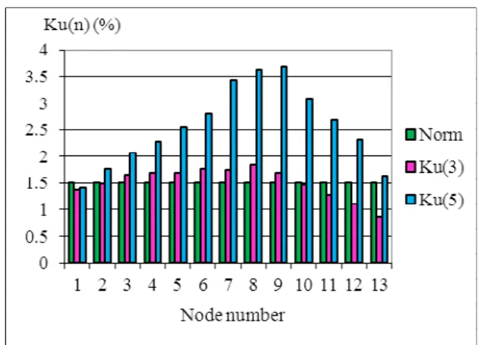
The filters are chosen for a radial section of a 13-node network. The section is about 600 km long. The distance between nodes is 40-60 km. At the nodes the substations feeding the traction network with nonlinear loads are connected. The values of KU(3)and KU(5) at the nodes without filters are presented in Fig. 2. The value of KU(3)
exceeds the admissible value 1.5% at seven nodes (at nodes 3 - 9), KU(5) - at 12 nodes (at nodes 2-13).
Node 7 is chosen for installation of filters of the 3-rd and 5-th harmonics. It was determined by the “test filter” described in [4]. The filters are chosen to decrease
) 3 ( U
K and KU(5) on a centralized basis at all nodes of the considered section.
The initial data for calculation of the 3-rd harmonic filter parameters in the program implementing the suggested
Fig. 2. KU(3) and KU(5)at the nodes without filters
algorithm are:
1) the value of KU(3) at the node of filter installation, that is equal to 1.78%;
2) the value of reactive powerQ1, generated by filter at the first harmonic, that is equal to 5 Mvar;
3) the value of KU(3) at the nodes after filter installation, that lies in the range from 0.5 to 1.2 %; 4) matrix of nodal resistances of the network Zn and
column matrix of voltages Un for the 3-rd harmonic at the nodes without filter, that are calculated with the software package HARMONICS, and are applied for calculation of Unfi in expression (9).
D. Determination of filter parameters
The numerical experiments made when determining filter parameters revealed that the particle swarm optimization gives a good convergence with 50 particles in the swarm. Iteration process is repeated until the conditions of finding the solution are satisfied. Such a condition for this problem was the number of iterations assumed equal to 200. But the method has fast convergence within 40-50 iterations. The objective function in these iterations tends fast to the minimum value.
After the work of the particle swarm optimization finished active losses in the filter at the 3-rd harmonic made up 27.7 kW. After the work of interior point technique was over active losses decreased to 27.54 kW which confirms good convergence of the particle swarm optimization.
The following parameters of the 3-rd harmonic filter were obtained: R=17360.50 Ohm, XL=1156.69 Ohm,
L
R =11.56 Ohm, XC1=10842 Ohm, XC2=249622.80 Ohm. Then in a similar manner the parameters of the 5-th harmonic filter are chosen. The initial operating conditions of the network are the conditions with the above chosen 3-rd harmonic filter. The calculated parameters of the 5-th harmonic filter are: R=18026 Ohm, XL=644.8 Ohm, RL=6.00 Ohm, XC1=16799 Ohm, XC2=385917 Ohm.
The values of KU(3) and KU(5) at the nodes with filters are shown in Fig. 3. They lie below the admissible value 1.5%, in the range specified during the optimization process.
Fig. 3. KU(3) and KU(5) at the nodes with filters
E. Analysis of an effect the filters have on the network Passive filters decrease harmonic voltages by adjusting the network properties. Let us analyze what happens with the parameters of network and operating conditions at the 5-th harmonic after installation of the 3-rd and 5-th harmonic filters. Imagine a network with respect to any node in the form of a current source and impedance. Then the voltage
ni
U at any i-th node at the n-th harmonic will be determined by the expression
ni ni
ni I /Y
U ==== , (17)
where Ini- the value of the n-th harmonic current of the current source at node i,
Yni- admittance of the n-th harmonic of the network with respect to node i.
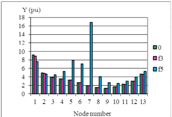
Fig.4 presents nodal admittances at the 5-th harmonic for the considered 13-node section with the following notation: (0) – without filters, (f3) the 3-rd harmonic filter is installed, (f5) – the 5-th harmonic filter is installed. After installation of the 3-rd harmonic filter nodal admittances changed insignificantly towards decrease or increase versus operation without filters. Owing to the installation of the 5-th harmonic filter at node 7 the 5-th harmonic admittance increased at eleven nodes. The 5-th harmonic admittance decreased only at two nodes that are the farthest from the node of filter installation. At the node of filter installation admittance increased by more than 8 times. The admittances also rose to a different degree at the remaining nodes, at which the same filter had to decrease the value ofKU(5). Analysis of the nodal admittances shows that the admittances changed due to reactive component of inductive character. Active component of admittance changed very insignificantly.
Fig. 4. Nodal admittances at the 5-th harmonic
Changes in the network admittances resulted in redistribution of the 5-th harmonic currents across the network. The nodal currents of the 5-th harmonic changed (Fig. 5). Installation of the 3-rd harmonic filter caused minor changes in the 5-th harmonic currents. Installation of the 5-th harmonic filter resulted in a considerable decrease in the 5-th harmonic currents at all nodes except node 7.
Analysis of calculations for the other harmonics shows that the third-order filter changes the considered network properties only at the harmonic the filter is tuned to. It virtually does not have any impact on the network and operation parameters at other harmonics.
Fig. 5. Values of the 5-th harmonic nodal currents
4. Conclusion
1. The optimization approach to calculate parameters of diverse passive filters for centralized reduction of harmonic voltages at HV network nodes with distributed nonlinear loads is suggested.
2. The optimization problem that applies the minimum of active power losses in the filter as an objective function, common constraints for different types of filters and individual constraints considering specific features of every type of filters are formulated.
3. The two-stage algorithm and the computer program are worked out on the basis of the suggested optimization approach by using the particle swarm optimization.
4. The case study demonstrating the application of the suggested algorithm to calculation of the third-order filter parameters is presented, which proved the algorithm efficiency.
Acknowledgement
This work was supported by the grant of the Leading Scientific School 1507.2012.8.
References
[1] State standard 13109-97. Electric energy. Electromagnetic compatibility of technical facilities. Standards of electric energy quality in the public electricity supply systems. – М. (1998). [2] C. Kawann, A. E. Emanuel, “Passive shunt harmonic filters for low and medium voltage: A cost comparison study”, IEEE Trans. on Power Systems, 1996, Vol. 11, No 4, pp. 1825-1331. [3] Gary W. Chang, Shou-Yung Chu, Hung-Lu Wang, “A new method of passive harmonic filter planning for controlling voltage distortion in a power system”, IEEE Trans. on Power Delivery, 2006, Vol. 21, No 1, pp. 305-312.
[4] L.I. Kovernikova, “Choice of harmonic filters for high
voltage networks with distributed nonlinear load”, in Proc. EPQU2007.
[5] L.I. Kovernikova, “Centralized normalization of voltage harmonics in the network with distributed nonlinear loads by the third-order filters”, Przegląd elektrotechniczny, 2011, No 1, pp.19-23.
[6] H. L. Ginn H. L., L. S. Czarnecki, “An optimization based method for selection of resonant harmonic filter branch parameters”, IEEE Trans. on Power Delivery, 2006, Vol. 21, No 3, pp.1445-1451.
[7] P. Mattavelli, “Design of harmonic filters for high-power ac/dc converters”, in Proc. IEEE Power Eng. Soc., Summer Meeting, 2000, pp. 795-799.
[8] L. A. Dobrusin, Z. T. Dzhafarov, “A comprehensive method and its application in designing filter compensating structures”, Elektrichestvo, 1986, No.8, pp.21-27. (In Russian)
[9] J. J. Grainger, W. D. Stevenson, Jr., Power system analysis. – International Editions, (1994).
[10] G. J. Wakileh, Power System Harmonics. – Springer-Verlag: Berlin, (2001).
[11] R. C. Eberhart, Y. Shi, “Particle swarm optimization: developments, applications and resources”. Proc. of the 2001 Congress on Evolutionary Computation, 2001, Vol. 1, pp. 81-86.
[12] R. H. Byrd, M. E. Hribar, J. Nocedal, “An interior point algorithm for large-scale nonlinear programming”, SIAM Journal on Optimization, 1999, Vol. 9, No 4, pp. 877-900. [13] Jos. Arrillaga, Power system harmonics /J. Arrillaga, N.R. Watson. - 2nd.ed. – Chichester: Wiley, (2003).