Top Layer Networks IPS 5500 E Security Target
Version 1.1
April 10, 2009
Prepared For:
Top Layer Networks
2400 Computer DriveWestborough, MA 01581
Prepared By:
CygnaCom Solutions
Security Evaluations Laboratory 7925 Jones Branch Drive, Suite 5200Table of Contents
1 INTRODUCTION... 1 1.1 IDENTIFICATION ... 1 1.2 CCCONFORMANCE CLAIM ... 1 1.3 OVERVIEW ... 1 1.4 ORGANIZATION ... 2 1.5 DOCUMENT CONVENTIONS ... 2 1.6 DOCUMENT TERMINOLOGY ... 3 1.6.1 ST Specific Terminology ... 3 1.6.2 Acronyms ... 5 2 TOE DESCRIPTION ... 7 2.1 TOEOVERVIEW ... 7 2.1.1 Categories of Deployment ... 8 2.2 ARCHITECTURE DESCRIPTION ... 12 2.3 PHYSICAL BOUNDARIES ... 14 2.3.1 Physical Interfaces ... 15 2.3.2 Evaluated Configuration ... 192.3.3 Security Functionality in the IT Environment ... 20
2.3.4 Management Interfaces ... 21
2.4 LOGICAL BOUNDARIES ... 21
2.4.1 Security Audit ... 22
2.4.2 User Data Protection ... 22
2.4.3 Identification and Authentication ... 22
2.4.4 Security Management ... 22
2.4.5 Protection of TOE Security Functions ... 22
2.4.6 Trusted Path/Channels ... 23
2.5 FUNCTIONALITY NOT INCLUDED IN THE TOESCOPE ... 23
3 TOE SECURITY ENVIRONMENT ... 24
3.1 ASSUMPTIONS ... 24
3.1.1 Usage Assumptions ... 24
3.1.2 Personnel Assumptions ... 24
3.1.3 Physical Environment Assumptions ... 24
3.2 THREATS ... 24
3.2.1 Threats Addressed by the TOE ... 25
3.3 ORGANISATIONAL SECURITY POLICIES ... 25
4 SECURITY OBJECTIVES ... 26
4.1 SECURITY OBJECTIVES FOR THE TOE ... 26
4.2 SECURITY OBJECTIVES FOR THE ENVIRONMENT ... 27
5 IT SECURITY REQUIREMENTS ... 29
5.1 TOESECURITY FUNCTIONAL REQUIREMENTS ... 30
5.1.1 Security Audit (FAU) ... 30
5.1.1.1 FAU_GEN.1 Audit data generation ... 30
5.1.1.2 FAU_GEN.2 User identity association ... 31
5.1.1.3 FAU_SAA.1 Potential violation analysis ... 31
5.1.1.4 FAU_ARP.1 Security alarms ... 32
5.1.1.5 FAU_SAR.1 Audit review ... 32
5.1.1.6 FAU_SAR.3 Selectable audit review ... 33
5.1.1.7 FAU_SEL.1 Selective audit ... 33
5.1.2 User Data Protection (FDP) ... 34
5.1.2.1 FDP_IFC.1 (1) Subset information flow control (1) ... 34
5.1.2.2 FDP_IFF.1 (1) Simple security attributes (1) ... 34
5.1.2.3 FDP_IFC.1 (2) Subset information flow control (2) ... 37
5.1.2.4 FDP_IFF.1 (2) Simple security attributes (2) ... 37
5.1.3 Identification and Authentication (FIA)... 42
5.1.3.1 FIA_AFL.1 Authentication failure handling ... 42
5.1.3.2 FIA_ATD.1 User attribute definition ... 42
5.1.3.3 FIA_UAU.1 Timing of Authentication ... 42
5.1.3.4 FIA_UAU.7 Protected authentication feedback ... 42
5.1.3.5 FIA_UID.2 User identification before any action ... 43
5.1.4 Security Management (FMT) ... 43
5.1.4.1 FMT_MOF.1 Management of security functions behaviour ... 43
5.1.4.2 FMT_MSA.1 Management of security attributes... 44
5.1.4.3 FMT_MSA.3 Static attribute initialisation ... 44
5.1.4.4 FMT_MTD.1 Management of TSF data ... 44
5.1.4.5 FMT_SMF.1 Specification of Management Functions ... 46
5.1.4.6 FMT_SMR.1 Security roles ... 47
5.1.5 Protection of TSF (FPT) ... 47
5.1.5.1 FPT_TST.1 TSF self-testing ... 47
5.1.5.2 FPT_FLS.1 Failure with preservation of secure state ... 47
5.1.6 Trusted Path/Channels (FTP) ... 48
5.1.6.1 FTP_TRP.1 Trusted Path ... 48
5.2 EXPLICITLY STATED TOESECURITY FUNCTIONAL REQUIREMENTS ... 48
5.2.1 Protection of TSF (FPT) ... 48
5.2.1.1 FPT_STM_EXP.1 Reliable time stamps ... 48
5.2.1.2 FPT_RVM_EXP.1 Partial Non-bypassability of the TSP ... 48
5.2.1.3 FPT_SEP_EXP.1 Partial TSF domain separation ... 49
5.3 SECURITY REQUIREMENTS FOR THE ITENVIRONMENT ... 49
5.3.1 Class FAU: Security audit ... 49
FAU_STG_ENV.1 Protected Audit Trail Storage ... 49
5.3.2 Class FIA: Identification and Authentication ... 50
5.3.2.1 FIA_UAU_ENV.1 User Authentication before Action ... 50
5.3.2.2 FIA_UID_ENV.1 User Identification before any Action ... 50
5.3.3 Class FPT: Protection of the TOE Security Functions ... 50
5.3.3.1 FPT_RVM_ENV.1 Non-bypassibility of the IT Environment ... 50
5.3.3.2 FPT_SEP_ENV.1 Domain Separation in IT Environment ... 50
5.3.3.3 FPT_STM_ENV.1 Reliable Time Stamps ... 50
5.4 TOESTRENGTH OF FUNCTION CLAIM... 50
5.5 TOESECURITY ASSURANCE REQUIREMENTS ... 50
6 TOE SUMMARY SPECIFICATION ... 52
6.1 TOESECURITY FUNCTIONS ... 52
6.1.1 Security Audit ... 53
6.1.1.1 SA-1 Audit Data Generation (FAU_GEN.1) ... 55
6.1.1.2 SA-2 User Identity Association (FAU_GEN.2) ... 55
6.1.1.3 SA-3 Potential violation analysis (FAU_SAA.1) ... 55
6.1.1.4 SA-4 Security alarms (FAU_ARP.1) ... 55
6.1.1.5 SA-5 Audit review (FAU_SAR.1) ... 55
6.1.1.6 SA-6 Selectable Audit Review (FAU_SAR.3)... 55
6.1.1.7 SA-7 Selective Audit (FAU_SEL.1) ... 56
6.1.1.8 SA-8 Protected Audit Trail Storage (FAU_STG.1) ... 56
6.1.2 User Data Protection ... 56
6.1.2.1 IFC-1 Rate Based Control (FDP_IFC.1 (1), FDP_IFF.1 (1)) ... 58
6.1.2.2 IFC-2 Intrusion Prevention (FDP_IFC.1 (2), FDP_IFF.1 (2)) ... 59
6.1.3 Identification and Authentication ... 60
6.1.3.5 IA-5 User identification before any action (FIA_UID.2) ... 60
6.1.4 Security Management ... 61
6.1.4.1 SM-1 Management of security functions (FMT_MOF.1) ... 62
6.1.4.2 SM-2 Static attribute initialisation (FMT_MSA.3) ... 62
6.1.4.3 SM-3 Management of security attributes (FMT_MSA.1) ... 62
6.1.4.4 SM-4 Specification of Management Functions (FMT_SMF.1) ... 63
6.1.4.5 SM-5 Management of TSF Data (FMT_MTD.1) ... 63
6.1.4.6 SM-6 Security Roles (FMT_SMR.1) ... 63
6.1.5 Protection of TOE Security functions ... 63
6.1.5.1 SP-1 TSF Self-testing (FPT_TST.1) ... 63
6.1.5.2 SP-2 Failure with preservation of Secure State (FPT_FLS.1) ... 64
6.1.5.3 SP-3 Partial Non-bypassability of the TSF (FPT_RVM_EXP.1) ... 64
6.1.5.4 SP-4 TSF Domain Separation (FPT_SEP_EXP.1) ... 64
6.1.5.5 SP-5 Reliable Time Stamps (FPT_STM_EXP.1) ... 65
6.1.6 Trusted Path/Channels ... 65
6.1.6.1 TC-1 Trusted Path (FTP_TRP.1) ... 65
6.2 SECURITY ASSURANCE MEASURES &RATIONALE ... 65
6.3 APPROPRIATE STRENGTH OF FUNCTION CLAIM ... 68
7 PROTECTION PROFILE CLAIMS ... 69
8 RATIONALE ... 70
8.1 SECURITY OBJECTIVES RATIONALE ... 70
8.1.1 Rationale For Threat Coverage ... 70
8.1.2 Rationale For Organizational Policy Coverage ... 73
8.1.3 Rationale For Assumption Coverage ... 73
8.2 SECURITY REQUIREMENTS RATIONALE ... 74
8.2.1 Security Functional Requirements for the TOE ... 74
8.2.2 Security Functional Requirements for the IT Environment ... 77
8.2.3 Explicitly Stated Requirements Rationale ... 78
8.2.4 Rationale for TOE Security Assurance Requirements ... 78
8.2.5 Rationale For IT Security Requirement Dependencies ... 78
8.3 TOESUMMARY SPECIFICATION RATIONALE ... 79
8.3.1 Rationale for TOE Security Functions ... 79
8.4 RATIONALE FOR STRENGTH OF FUNCTION CLAIM ... 81
8.5 PROTECTION PROFILE CLAIMS RATIONALE ... 81
List of Tables
Table 1-1: ST Organization and Description ... 2
Table 2-1 Hardware Models ... 15
Table 2-2 Port Types ... 16
Table 2-3 Port Information ... 16
Table 2-4 Port Roles ... 18
Table 5-1: Security Functional Requirements for the TOE ... 29
Table 5-2: Auditable Events ... 30
Table 5-3: Management of security functions behaviour ... 43
Table 5-4 Management of TSF Data ... 44
Table 5-5: Security Functional Requirements for the IT Environment ... 49
Table 5-6 - Assurance Requirements: EAL4 ... 50
Table 6-1: TSF Description ... 52
Table 6-2 - Assurance Measures & Rationale: EAL4 ... 65
Table 8-1 -All Threats to Security Countered... 70
Table 8-2 - All Objectives for the TOE Met by Functional Requirements for the TOE ... 74
Table 8-3 - All Objectives for the IT Environment Met by SFRs for IT Environment ... 77
Table 8-4 – SFR Dependencies... 78
Table 8-5 – TOE Security Function to SFR Mapping ... 79
Table 9-1 References ... 82
List of Figures
Figure 2-1 IPS Unit‘s Security ... 8Figure 2-2 Network Perimeter Protection ... 8
Figure 2-3 Protection for a Hosting Center... 9
Figure 2-4 Protect Critical Online Assets ... 10
Figure 2-7 TOE Multi- Stage Architecture ... 14
Figure 2-8 Evaluated Configuration ... 19
Figure 2-9 Evaluated Configuration with High Availability Feature ... 20
Figure 6-1 IPS Unit Security Checks ... 56
Figure 6-2 Rate Based Security ... 57
1
Introduction
This section identifies the Security Target, Target of Evaluation (TOE), conformance claims, ST organization, document conventions, and terminology. It also includes an overview of the evaluated product.
1.1
Identification
TOE Identification: Top Layer Networks IPS 5500 E Version 5.21 software running on an IPS 5500 E series hardware platform.
The IPS 5500 series product line includes the following hardware models:
- IPS 5500-150E,
- IPS 5500-500E and
- IPS 5500-1000E
ST Identification: Top Layer Networks IPS 5500 E Security Target
ST Version: 1.1
ST Publish Date: April 10, 2009
ST Authors: CygnaCom Solutions
PP Identification: None
1.2
CC
Conformance
Claim
The TOE is Common Criteria (CC) Version 2.31 Part 2 extended.
The TOE is Common Criteria (CC) Version 2.3 Part 3 conformant and meets the requirements of Evaluation Assurance Level (EAL) 4.
There are no applicable International (CCIMB) interpretations for CC Version 2.3 as of 12/21/2008.
This TOE is not conformant to any Protection Profiles (PPs).
1.3
Overview
The Top Layer IPS 5500 E is a single-appliance security gateway Intrusion Protection System. The IPS Unit provides network-level and application-level protection to a network from good, bad and suspicious traffic. It is a hardware-based, multi-processor system that has an onboard application level stateful firewall that works in conjunction with the Intrusion Prevention subsystems to provide security. The IPS 5500 provides a 3-Dimensional approach to secure networks of interest to:
- Stop Resource Abuse
- Prohibit Access to Unauthorized Clients
- Stop Malicious Content
The IPS Unit supports a number of management interfaces to manage it both locally and using a remote system. It provides logging of various security events.
1.4
Organization
Table 1-1: ST Organization and Description
Section Title Description
1 Introduction Provides an overview of the Security Target.
2 TOE Description Defines the hardware and software that make up the TOE,
and the physical and logical boundaries of the TOE.
3 TOE Security
Environment
Contains the threats, assumptions and organizational security policies that affect the TOE.
4 Security Objectives Contains the security objectives the TOE is attempting to meet.
5 IT Security Requirements Contains the functional and assurance requirements for this TOE.
6 TOE Summary
Specification
A description of the security functions and assurances that this TOE provides.
7 PP Claims Protection Profile Conformance Claims
8 Rationale Contains pointers to the rationales contained throughout
the document.
1.5
Document Conventions
The notation, formatting, and conventions used in this security target (ST) are consistent with version 2.3 of the Common Criteria for Information Technology Security Evaluation. All of the components in this ST are taken directly from Part 2 of the CC except the ones noted with ―_EXP‖ in the component name. Font style and clarifying information conventions were developed to aid the reader.
The CC permits four functional component operations: assignment, iteration, refinement, and selection to be performed on functional requirements. These operations are defined in Common Criteria, Part 1 as:
Iteration: allows a component to be used more than once with varying operations; Assignment: allows the specification of parameters;
Selection: allows the specification of one or more items from a list; and Refinement: allows the addition of details.
This ST indicates which text is affected by each of these operations in the following manner: Iterations are identified with a number in brackets "(#)" right after the short name. Assignments and Selections specified by the ST author are in [italicized bold text]. Refinements to the CC text are specified bold and underlined text.
Explicitly Stated TOE Security Functional Requirements are specified with a ―_EXP‖ added to the component name.
IT Environment Requirements are specified with a ―_ENV‖ added to the component name. Application notes provide additional information for the reader, but do not specify
requirements. Application notes are denoted by Application Note: italicized text.
CCIMB Interpretations have been reviewed. The original CC text modified by the interpretation is neither denoted nor explained.
1.6
Document Terminology
Please refer to CC Part 1 Section 2.3 for definitions of commonly used CC terms.
1.6.1 ST Specific Terminology
External IT entity -- Any IT product or system, untrusted or trusted, outside of the TOE, that interacts with the TOE.
Identity -- A representation (e.g. a string) uniquely identifying an authorized user, which can either be the full or abbreviated name of that user or a pseudonym. Authentication data -- Information used to verify the claimed identity of a user.
Authorized Administrator - An administrator who has been identified and authenticated by the TOE and has been granted the authority to manage the TOE. These users are expected to use this authority only in the manner prescribed by the guidance given to them.
Service - A service is a policy element that identifies a protocol or set of protocols to the IPS Unit, for example, HTTP, DNS, or FTP.
Rules - The IPS Unit contains hundreds of rules that it uses to check whether a given flow of traffic is acceptable or not. A rule may be based on packet checks (for example, Illegal ICMP Header) or protocol checks (for example, HTTP Unknown Method Name).
Actions - An action is a response by the IPS Unit when traffic triggers a security rule. The IPS Unit can take one of the following actions when traffic triggers a rule:
Allow — The IPS Unit passes the traffic.
Drop — The IPS Unit discards the traffic.
Reject — The IPS Unit discards the traffic and sends TCP reset to the connection source.
Client (Client Group) -An IT entity (group of IT Entities) that is the source of an information flow.
Server (Server Group) – An IT entity (group of IT Entities) to which an information flow is destined.
Host Groups (Client and Servers) - A host group is a named set of IP address ranges. A host group can define a group of clients or a group of servers. A given host group may act as both clients and servers.
Connection Limits — Limits the number of simultaneous connections allowed for a
group of clients or a group of servers, and for individual members of the group.
Request Limits — Limits the number of requests a client within a host group can make per minute for specified services.
SYN Flood Limits — Provides limits for the number of incomplete SYN requests for
servers and for various categories of clients (trusted, suspicious, malicious, etc.).
IP Address--Internet Protocol Address, a 32-bit numeric identifier for a computer or a device on the network. The TOE does not support IPv6 packets.
Segments – A pair of physical ports that handle internal and external network traffic (mission ports) is called a Segment. When configured to do so, the IPS Unit forwards all packets received on either of the ports in the pair to the other port in the pair, subject to the defined security policy filtering
Threat - Capabilities, intentions and attack methods of adversaries, or any circumstance or event, with the potential to violate the TOE security policy.
Threat Agent - Any human user or Information Technology (IT) product or system, which may attempt to violate the TSP and perform an unauthorized operation with the TOE.
TOE Security Function (TSF) Data - Information used by the TSF in making TOE security policy (TSP) decisions. TSF data may be influenced by users if allowed by the TSP. Security attributes, authentication data and information flow control policy‘s subject and object security attributes are examples of TSF data.
Audit Data - The logs generated based on the actions of the TOE itself. This includes the authentication of users accessing the TOE, actions taken directly on the TOE, and actions of the TOE itself. Audit data is a type of TSF data.
User - Any entity (human user or external IT entity) outside the TOE that interacts with the TOE.
User Data - Data created by external IT entities that does not affect the operation of the TSP. User data is separate from the TSF data. The information flows created by Clients and Servers is an example of user Data.
VPN-Virtual Private Network, a network constructed using public wires to connect nodes. For example, there are a number of systems that enable the administrator to create networks using the Internet as the medium for transporting data; these systems use encryption and other security mechanisms to ensure that only authorized users can access the network and that the data cannot be intercepted
Vulnerability - A weakness that can be exploited to violate the TOE security policy.
Protocol Validation - Examining the payload of application datagrams and application streams for specific network protocols (DNS, FTP, HTTP, MSNET, SIP, SSH and Telnet) to ensure that the traffic conforms to the rules for a given protocol as well as the IPS Unit‘s rules for reasonable usage. The protocol validation rules are specific to the Top Layer IPS. These rules enable configuration of protocol specific parameters for application protocols to stop attackers who abuse weaknesses in a protocol‘s defined structure.
Content Inspection - Checks for deliberate inclusion of malicious data or other malicious payloads into traffic that is otherwise well formed.
Attack Signatures - An attack signature is a defined arrangement of information that can be used to identify an attacker's attempt to exploit a known vulnerability.
Firewall Rules — Rules to provide classic firewall blocking for traffic, based on IP addresses, Layer 4 ports and segments (port pairs).
IPS Rules — Rules to provide the following types of checks:
Protocol validation
Attack Signatures
Acceptable use of network application
Rate Based Rules — Rules to protect your resources from overuse by legitimate users, as well as abusive denial-of-service attackers.
Bypass- The IPS Unit provides a software-based bypass feature between Mission port-pairs. There are three modes of bypass control.
- Never Bypass - The IPS Unit inspects all traffic, mitigates problem traffic, and records all information. All traffic flows through the IPS Unit‘s functions.
- Always Bypass - The IPS Unit inspects all traffic and records traffic statistics, but does not mitigate. All traffic always passes through the IPS Unit.
- Bypass During System Reset - The IPS Unit starts out performing as in Never Bypass mode, checking and mitigating all traffic, but performs as Always Bypass mode (passes all traffic) if there is a software failure and the IPS Unit needs to reboot.
1.6.2 Acronyms
The acronyms used within this Security Target:
Table 1-2 Acronyms Acronym Definition
ACM Configuration Management ADO Delivery and Operation ADV Development
AGD Guidance Documents ALC Life cycle support
ASIC Application-Specific Integrated Circuit
ATE Tests
AVA Vulnerability assessment
CC Common Criteria [for IT Security Evaluation] CIFS Common Internet File System
DNS Domain Name System EAL Evaluation Assurance Level FAU Security Audit
FDP User Data Protection
FIA Identification and Authentication FMT Security Management
Acronym Definition
GUI Graphical User Interface HTTP Hypertext Transfer Protocol
HTTPS Hypertext Transfer Protocol over SSL ICMP Internet Control Message Protocol ID Identifier
IP Internet Protocol
IPS Intrusion Protection System IT Information Technology LAN Local Area Network MAC Media Access Control MSNET Microsoft NETworks NIC Network Interface Card OS Operating System SF Security Function
SIP Session Initiation Protocol SMTP Simple Mail Transfer Protocol
SNMP Simple Network Management Protocol SFP Security Function Policy
SSH Secure Shell SSL Secure Socket Layer ST Security Target
TCP Transmission Control Protocol TOE Target of Evaluation
TSC TSF Scope of Control TSF TOE Security Functions
TSFI TOE Security Functions Interface TSP TOE Security Policy
TSS TOE Summary Specification UDP User Datagram Protocol VPN Virtual Private Network
2
TOE Description
2.1
TOE Overview
The TOE is an IPS 5500 E Hardware appliance with Version 5.21 software. The IPS Unit is managed using a Graphical User Interface (GUI), which is a Java Web Start™ application that runs as a stand-alone application on the Management Station. The Java Web Start application is also included in the TOE. The TOE acts as an inline single-appliance security gateway providing three-dimensional protection to stop resource abuse prohibit access to unauthorized clients and stop malicious content from entering the protected network. Top Layer‘s s ASIC technology and algorithms integrate stateful analysis techniques with deep packet inspection chip set and DoS (Denial of Service) attack protection to provide protection from Internet-based and internal threats. The difference between the TOE and a typical IDS is that the TOE (IPS Unit) is deployed inline and not in an offline or a passive mode.
The TOE may be configured to:
- Handle IP fragments, TCP header and Payload.
- Implement firewall rules.
- Perform protocol analysis.
- Perform deep packet inspections.
- Handle network and security management.
- Process events, logging, and reports.
The primary design goal of the TOE is reliable protection of the customer‘s critical on-line assets. The IPS aspect of the TOE security policy may be configured based on the following three types of rules. The rules guide the following types of security checks:
Firewall Rules — Provide classic firewall blocking for traffic, based on IP addresses, Layer 4 ports, and segments (port pairs).
IPS Rules — Provide the following types of checks:
• Protocol validation
• Attack Signatures
• Acceptable use of network application
Rate Based Rules — Protect resources from overuse by legitimate users, as well as abusive denial-of-service attackers. Provide limits for:
• Client requests
• Connections for both clients and servers
• SYN Flood controls
Figure 2-1 IPS Unit’s Security
2.1.1 Categories of Deployment
The figures in this section provide general guidelines to a prospective customer for placing an IPS Unit in their networks.
To install and deploy the TOE in a secure evaluated configuration please see section 2.3.2 Evaluated Configuration. Also, please see section 2.3.3 Security Functionality in the IT Environment for a description of the security functionality provided by the IT Environment. The IPS Unit can be deployed in the following ways in a prospective customer‘s network:
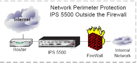
Network Perimeter Protection
Increases protection against targeted DDoS attacks and application level threats. Protects the network from cyber-threats that may traverse the VPN link.
Hosting Center Protection
Protects assets from network and application level threats regardless of whether they originate from inside or outside. The IPS unit when deployed this way could be used to protect servers in a dedicated manner.
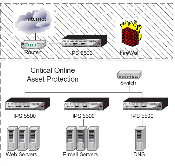
Figure 2-3 Protection for a Hosting Center Critical Online Assets Protection
Protects network segments from threats and provides containment of infected segments. When IPS units are deployed between internal network segments, they can be configured with network segment specific policies, which provide better performance. This configuration can also keep infected segments separate from uninfected segments.
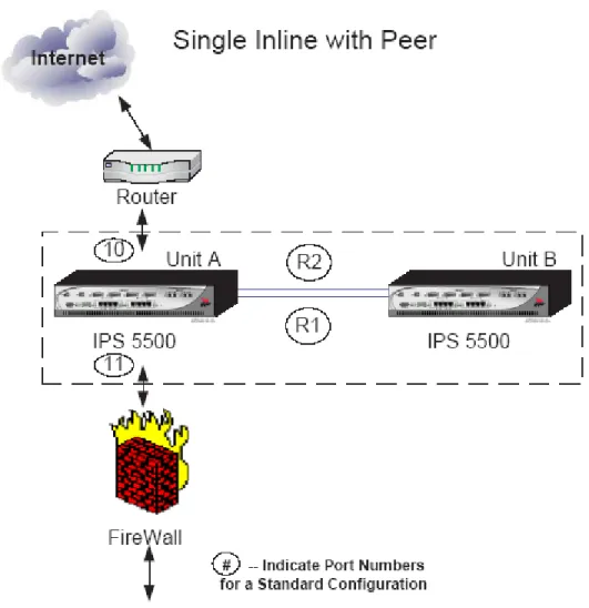
Figure 2-4 Protect Critical Online Assets High Volume Configuration Single Inline with Peer
Provides additional, shared processing for high volume environments. In the Single Inline with Peer configuration, only one IPS Unit passes network traffic, but the second IPS Unit assists in detection processing and flow setup operations, increasing the traffic load that the IPS Units can handle and almost doubling the number of connections that can be created and analyzed.
Figure 2-5 High Volume Single Inline with Peer ProtectionCluster Configuration
Provides active redundancy to the current configuration. ProtectionCluster refers to a network configuration option that provides higher bandwidth and redundancy. This configuration connects multiple IPS Units together using a special pair of GbE links. These links, called R1 and R2, provide higher bandwidth for flow rebalancing in redundant configurations. A ProtectionCluster configuration also enables the IPS Units to share the intense processing required for deep and stateful protocol analysis necessary to detect attempted exploits
of application-level vulnerabilities in both server and client groups. In this configuration, both sides of the configuration receive and pass the network traffic, unless there is a failure. This solution provides a redundant solution that offers maximum protection of the network resources. This solution, using a combination of IPS Units, protects up to two full duplex Gigabit input ports: stopping the "bad" traffic, while permitting the ―good‖ traffic to pass to its destination.
Figure 2-6 Two Unit Protection Cluster
2.2
Architecture Description
The TOE architecture offers network-level and application-level protection along with the flexibility to integrate application-specific protection mechanisms. Top Layer‘s
ASIC technology provides the high-performance base required for protecting against
internet based and internal threats. The TOE provides stateful analysis firewall technology to provide network level protection, identifying undesired access, illegal packets, illegal headers, and various network attacks. Top Layer‘s denial-of-service protection algorithms are used by the TOE to protect against flood-based attacks, such as ICMP, UDP, and TCP SYN Floods.
The TOE uses a packet inspection chip set to provide application-level protection against exploits of critical vulnerabilities, including worms and application-level attacks.
The TOE is composed of the following logical subsystems:
- L2 Filters
- DDos Filters
- Resource Limit Filters
- Stateful Analysis
- Firewall Filters
- Protocol Validation
- Content Inspection
Each subsystem performs a set of specific checks.
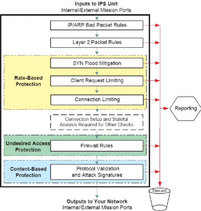
These specific checks, or rules, and their associated actions, make up the subsystem‘s security policy. The IPS unit organizes the subsystems in a particular order so that traffic that is filtered by an earlier subsystem is never seen by the later subsystems. The various subsystems work together to provide the three-dimensional security protection
The figure below depicts the TOE as a device with multiple stages of security filtering performed by the subsystems mentioned above.
Figure 2-7 TOE Multi- Stage Architecture
2.3
Physical Boundaries
The physical boundary of the TOE is the IPS 5500 E Hardware appliance (150 E, 500 E or 1000 E) loaded with the IPS Software Version 5.21.
2.3.1 Physical Interfaces
The TOE has the following physical interfaces:
- Console port using a 9-pin D-sub connector
- 10BASE-T/100BASE-TX copper LAN ports,
- 1000BASE-T Copper ports
- 1000BASE-SX fiber optic HA
Please see the table below for more details on the hardware models:
Table 2-1 Hardware Models
Model CPU Ports Memory NIC Chipsets Used Power Supply
150 E, 500E and 1000E
The TOE utilizes multiple CPU's. - 5 Top Layer proprietary ASIC chips running at 100 MHz - 1 AMD 520 chip running at 100 MHz - 2 Freescale PowerPC chips running at 825 MHz Total Number of NIC Ports: 12 Total Number of Serial Ports: 1 Total number of HA Ports: 2 There is no hard drive in the TOE. It does utilize a 256 Meg compact flash card. 10/100 A combination of a Top Layer proprietary ASIC MAC chip and Marvell transceiver chip (Marvell part number 88E3082-BAR) 1 or 2 1000 (Port Numbers 9 to 12) A combination of a Top Layer proprietary ASIC MAC chip and HP IC SerDes Gigabit chip (HP part number HDMP-1646A) 1000 (R1 and R2) A combination of a Top Layer proprietary ASIC MAC chip and Marvell IC Gigabit quad Phy SerDes chip (Marvell part number 88E1043-D2-BCA-C000)
Each hardware model has 12 physical ports numbered 1 to 12 and two high availability ports numbered R1 and R2. Most of the ports on the IPS Unit can have several possible roles. A port
In addition to port roles, the IPS unit supports the concept of Mission, Management, and Maintenance ports to further classify ports based on their role type.
Mission ports are ports that handle internal and external network traffic. Two matched ports, one with the role Internal and another port with the role External, are known as a Mission port-pair. Management ports on the IPS unit are ports used to manage the IPS unit itself. By default, Port 8 on the IPS Unit is always configured to be a Management access port. All configured
Management ports are bridged together and flooding occurs between these ports. An internal bridge logically connects Management ports. Packets received on Management ports are bridged to other Management ports. Packets received on Mission ports can be bridged to other Mission ports, but will never be forwarded to any Management port or to the management entity (e.g. management station).
Maintenance ports are ports on the IPS unit that are used to manage events and mirror traffic on the IPS unit. These ports can have the role of Capture, Mirror, or Discard. Traffic on
maintenance ports is handled using the Management Bridge.
The IPS Unit uses these roles and port types to determine how traffic passes through the IPS Unit. The table below presents details of Roles, Port Types and traffic isolation.
Table 2-2 Port Types
Role Port Type Traffic Isolation Handled by
Internal or External Mission Port Mission Bridge Management Management Port Management Bridge Capture, Mirror, Discard Maintenance Management Bridge High Availability HA Port Not Applicable
The table below presents details of each port speed, possible roles, and the default role for each Port on the hardware models. Please note that the Port # in the first column in the table below represents the physical port number and not the number of ports.
Table 2-3 Port Information
Port # Speed Possible Roles Default Role IPS 5500-150 IPS 5500-500 IPS 5500-1000 1 10/100 External, Mirror, Unused External 2 10/100 Internal, Mirror, Unused Internal 3 10/100 External, Mirror, Capture, Capture
Port # Speed Possible Roles Default Role IPS 5500-150 IPS 5500-500 IPS 5500-1000 Unused 4 10/100 Internal, Mirror, Capture, Discard, Unused Discard 5 10/100 Management, Mirror, Capture, Discard, Unused Unused 6 10/100 Management, Mirror, Capture, Discard, Unused Unused 7 10/100 Management, Capture, Discard, Unused Unused 8 10/100 Management Management 9 1000 External Unused External 10 1000 Internal Unused Internal 11 1000 External, Capture, Unused Unused 12 1000 Internal, Capture, Unused Unused R1 1000 HA HA R2 1000 HA HA
The following table explains the port roles. Please note that the # of Ports in the second column represents the number of ports, not the physical port number.
Table 2-4 Port Roles
Port Role # of Ports that can have this Role
Operating Speed
Description
Management 1,2,3,or 4 10/100 Use a port with the port role Management to manage the IPS Unit and as an output port for reporting traffic (using standard Syslog and SNMP traps).
Mirror 0,1,2,3,4,5, or 6
10/100 Identify one or more Mirror ports to create a mirror (copy) group. The IPS Unit copies all packets from specific traffic applications to the ports in the mirror group. It uses the Round Robin algorithm to balance traffic among the Mirror ports.
All ports in the mirror group must be set to the same speed.
No packets are received on a port with this role. Discard 0 or 1 10/100 Use a port with the role Discard to send the dropped
packets that caused events to a collecting system in the environment. Configure which packets go through the Discard port to the collecting system in the environment by configuring Policies
Capture 0 or 1 10/100/1000 Use a port with the role Capture as a single, mirroring output port. One of the Mission ports can be chosen to have all of its received and transmitted packets mirrored to this port.
External (Outside)
1,2,3, or 4 10/100/1000 Use a port with the role External to connect to the external network. The External port does not allow management access. The External port receives packets and forwards them (subject to policy checks) to its paired Internal port (known as Port-pair forwarding mode),
Internal (Inside)
1,2,3, or 4 10/100/1000 Use a port with the role Internal to connect to the internal network. The Internal port does not allow management access. The Internal port receives packets and, either forwards them (subject to policy checks) to its paired External port (known as Port-pair forwarding mode), or bridges them according to their destination MAC addresses.
High Availability
0,1, or 2 1000 Use a port with the role High Availability (HA) as a Gigabit port that is directly connected to a redundant IPS Unit. The HA port is used to balance traffic between redundant IPS Units.
Unused Not Applicable
10/100/1000 A port with the role Unused is a port that is not configured. The Unused port does not accept traffic nor send any traffic. The IPS Unit will not recognize a link to this port.
2.3.2 Evaluated Configuration
Figure 2-8 Evaluated Configuration below depicts the TOE in the evaluated configuration.
Figure 2-8 Evaluated Configuration
The IPS Unit is managed using a Graphical User Interface (GUI), which is a Java Web Start™ application that runs as a stand-alone application on the Management Station. The Java Web Start application is also included in the TOE.
In addition to the evaluated configuration shown above where a single IPS unit is used between networks, an additional configuration which includes two IPS units was used to test the
Protection Cluster capability. This configuration ensures that if the IPS unit fails or is taken off-line, the second IPS unit takes the entire load, ensuring continued network operation.
Figure 2-9 Evaluated Configuration with High Availability Feature
Note: Customers who install only one IPS box (i.e., operating in the ―single IPS box‖ mode of operation as shown in Figure 2-8 Evaluated Configuration) are also in the evaluated
configuration.
2.3.3 Security Functionality in the IT Environment
The TOE depends on the IT Environment for the following security functions:
- Web browser – Used to access TOE administrative interfaces and displays alerts, reports, statistics, diagnostics and security logs
- SMTP, SNMP, Syslog servers – Used to receive audit events generated by the TOE
- NTP server – Used to set TOE hardware clock
The external IT entities send and receive network traffic through the TOE. Packet Capture Systems receive packets from Capture, Discard and Mirror Ports.
2.3.4 Management Interfaces
The TOE supports a number of management interfaces:
Serial Console — The CONSOLE port on the front of the IPS Unit provides access to a limited
Command Line Interface that can be used to perform basic setup.
Command Line Interface over Telnet —An extended CLI can be accessed using a Telnet
session. The CLI provides access to nearly all the IPS Unit‘s configuration and management commands.
Graphical User Interface Access using HTTP and HTTPS — The Graphical User Interface
(GUI) runs as a Java Web Start™ program over the World Wide Web. The GUI provides interface windows for configuring and managing the IPS Unit and provides access to context sensitive online help. The Java Web Start™ application, which communicates with the TOE to manage the TOE, is also included in the TOE. The application is loaded from the IPS 5500 E onto the client host and allows the administrator to affect the IPS 5500 E configuration and load audit information off the IPS 5500 E.
SNMP — The IPS Unit‘s Simple Network Management Protocol interface provides read-only
access to many of the IPS Unit‘s settings.
IPS Controller — The IPS Controller is a separate product from Top Layer that allows for
central management of multiple IPS Units.
All of the management interfaces described above, except the serial console, can be used to manage the TOE through a network interface port with management role.
In the evaluated configuration, management of the TOE, apart from the basic setup using the serial console, is done using the Graphical User Interface (GUI), which connects to the TOE over HTTPS.
2.4
Logical Boundaries
The security functions provided by the TOE include:
- Security audit
- User Data Protection
- Identification and authentication
- Security management
- Protection of TOE Security Functions
2.4.1 Security Audit
During the process of receiving and transmitting traffic, the TOE performs many checks and operations. Some of these operations, system events, and user-related management interface tasks produce event messages. The IPS Unit contains a message managing system that makes these messages available to the user based on the message controls established. These messages are collected as audit records in Alert logs and Event Log files. The TOE may also be configured to send messages to remote Syslog and SNMP servers. Only human users with authorized
administrator or monitor privileges have the capability to view the audit data stored on the TOE. See the corresponding section in the TSS for more detailed information.
2.4.2 User Data Protection
The TOE performs user data protection through the rate based security policy, the firewall
filtering security policy, and the intrusion prevention security policy. The TOE identifies external IT entities and remote administrator systems by their presumed IP addresses. Only legitimate external IT entities and authorized administrator systems are granted access to pass information through the TOE or to the TOE.
See the corresponding section in the TSS for more detailed information.
2.4.3 Identification and Authentication
The TOE provides a password based authentication mechanism to users with the administrator and monitor role. The TOE communicates with the remote web browser of the administrator using the HTTPS protocol in order to encrypt the user id, password authentication data, and all configuration information to maintain secrecy from an attacker. IT Entities are identified by their presumed IP addresses. Access to security functions and data is prohibited until a user is
identified and authenticated.
See the corresponding section in the TSS for more detailed information.
2.4.4 Security Management
The TOE maintains administrator and monitor user management roles.
The TOE allows only authorized users with appropriate privileges to administer and manage the TOE. An administrative user can connect through an encrypted web interface using SSL for secrecy. Only authorized administrators may modify the TSF data related to the TSF, security attributes, and authentication data.
See the corresponding section in the TSS for more detailed information.
2.4.5 Protection of TOE Security Functions
The TOE transfers all the packets passing through the TOE only after processing the traffic based on the traffic attributes.
The TOE restricts management access to its interfaces by requiring users to log into the TOE using its GUI. HTTPS is used to protect the connection between the web browser in the IT
Environment and the appliance. The TOE relies on Top Layer appliance hardware to ensure the TSP is enforced and to provide for domain separation. The TOE hardware appliance includes its own hardware clock, which provides reliable time stamps for use in audit and collected data records.
See the corresponding section in the TSS for more detailed information
2.4.6 Trusted Path/Channels
The TOE, in conjunction with the IT environment, protects the TSF data from unauthorized disclosure or modification of TSF data when it is being transmitted between the IPS Unit and the management GUI on the remote management station.
See the corresponding section in the TSS for more detailed information.
2.5
Functionality Not Included in the TOE Scope
The following features do not contribute to meeting any of the Security Functional Requirements (SFRs) and are not included in the TOE scope:
- VLAN Support
- Management of the IPS with an IPS Controller, Command Line Interface over Telnet and SNMP (Get function)
- Usage of the TOE with other Top Layer supporting products (Network Security Analyzer, IPS Controller, TopResponse Software)
- Note: The functionality/protocol used by the TopResponse product to automatically update signatures is included in the scope of the evaluation. The TSFI for this functionality is included in the scope of the evaluation, documented in the FSP and is verified during testing. Hence the capability of the TOE to download latest set of “TopLayer Protection Packs” is included in the Scope of the evaluation.
3
TOE Security Environment
The TOE is intended to be used in environments in which sensitive information is processed. This section contains assumptions regarding the security environment and the intended usage of the TOE and threats to the TOE and the IT environment.
3.1
Assumptions
The assumptions are ordered into three categories: usage assumptions, personnel assumptions and physical environment assumptions.
3.1.1 Usage Assumptions
A.CONNECT The TOE will separate the network on which it is installed and operates into external, internal and management networks. Information cannot flow between the external and internal networks without passing through the TOE.
A.BACKUP Administrators will back up the audit files, configuration files and monitor disk usage to ensure audit information is not lost.
3.1.2 Personnel Assumptions
A.NOEVIL There will be one or more competent individuals assigned to manage the TOE and the security of the information it contains. The authorized administrators are not careless, willfully negligent, or hostile, and will follow and abide by the
instructions provided by the TOE documentation.
A.AUTH It is assumed that administrators will protect their authentication data.
3.1.3 Physical Environment Assumptions
A.PHYSICAL The TOE hardware and software critical to security policy enforcement will be protected from unauthorized physical modification and the processing resources of the TOE will be located within controlled access facilities, which will prevent unauthorized physical access.
3.2
Threats
The TOE addresses the threats identified in this section. The threat agents are authorized persons/processes, unauthorized persons/processes, or external IT entities not authorized to use the TOE itself. The threats identified assume that the threat agent is a person with a low attack potential who possesses an average expertise, few resources, and low to moderate motivation. The assumed level of expertise of the attacker is unsophisticated, with access to only standard equipment and public information about the product.
3.2.1 Threats Addressed by the TOE
The TOE addresses the threats discussed below.
T.NOAUTH An unauthorized person may attempt to bypass the security of the TOE so as to access and use security functions and/or non-security functions provided by the TOE.
T.MANAGE An unauthorized person or unauthorized external IT entity may be able to view, modify, and/or delete TSF data on the TOE
T.PROCOM An unauthorized person or unauthorized external IT entity may be able to view, modify, and/or delete security related information that is sent between a remotely located authorized administrator and the TOE.
T.REPEAT An unauthorized person may repeatedly try to guess authentication data in order to use this information to launch attacks on the TOE.
T.AUDIT Unauthorized attempts by users and external IT entities to access network resources through the TOE, TOE data or TOE security functions may go
undetected because the actions they conduct are not audited or audit records are not reviewed, thus allowing an attacker to escape detection.
T.RATEBASED
An External IT Entity may exhaust service resources of the TOE or systems by passing information flows thorough the TOE.
T.ADDRESSSPOOF
An External IT Entity may illegitimately gain access to networks through the TOE by spoofing source IP address.
T.UNDESIREDACCESS
An External IT Entity may send impermissible information through the TOE, which results in the exploitation of resources.
T.CONTENTBASED
An External IT Entity may attack or tamper resources by sending information flows through the TOE, which contain malicious data or malicious inclusion of payloads that is otherwise well formed
3.3
Organisational Security Policies
4
Security Objectives
This chapter describes the security objectives for the TOE and the TOE‘s operating environment. The security objectives are divided between TOE Security Objectives (i.e., security objectives addressed directly by the TOE) and Security Objectives for the Operating Environment (i.e., security objectives addressed by the IT domain or by non-technical or procedural means).
4.1
Security Objectives For The TOE
This section defines the IT security objectives that are to be addressed by the TOE.
O.IDAUTH The TOE must uniquely identify and authenticate the claimed identity of all administrative users, before granting an administrative user access to TOE functions.
O.SELFPROTECTION
The TOE must protect itself against attempts by unauthorized users to bypass, deactivate, or tamper with TOE security functions.
O.MANAGE
The TOE must protect stored TSF data from unauthorized disclosure, modification, or deletion.
O.ADMINISTRATION
The TOE must provide all the functions necessary to support the authorized users in their management of the security of the TOE. The TOE must provide the capability to allow or disallow remote administration of the TOE.
O.AUDIT The TOE must provide a means to record, store and review security relevant events in audit records to trace the responsibility of all actions regarding security. O.ALERT The TOE must provide a record of the attacks detected and blocked by the TOE. O.AUDITPROTECT
The TOE must provide the capability to protect audit information residing on the TOE.
O.UNDESIREDACCESS
The TOE must control unauthorized information flow between internal and external networks based on security policies.
O.RATEBASED
The TOE must limit resource usage to an acceptable level (stop legitimate clients from overusing resources and stop DDoS and other network flooding attacks). The TOE must be able to serve as a rate based controller and police both malicious users who attempt to flood the network with DoS and DDoS attacks, and authorized users who may overuse resources.
The TOE must filter the content in the information flows through the TOE to prevent malicious intruders from exploiting system vulnerabilities or network based protocol weaknesses, as well as more direct attacks through e-mail based worms and viruses.
O.TIME The TOE must provide a reliable clock to maintain the system time. O.TRANSMISSION
The TOE must provide a HTTPS session for communication between the User Management GUI on the Management Station and the TOE.
Application Note: A Management Station is a workstation on the management network that the TOE administrator uses to access the TOE using an HTTPS enabled web browser. There can be one or more Management stations.
4.2
Security Objectives For The Environment
The following are the IT security objectives that are to be addressed by Environment
OE.AUDIT The IT environment must provide a long term audit and alert store for the TOE. OE.PROTECT
The IT environment must protect itself against attempts by unauthorized users to bypass, de-activate, or tamper with its security functions.
OE.TIME The IT environment must be configured with an NTP server that is able to provide reliable time to the TOE.
The following are the non technical IT security objectives that are to be addressed by the
Environment. The non-IT security objectives for the environment listed below are to be satisfied without imposing technical requirements on the TOE. Thus, they will be satisfied through application of procedural or administrative measures.
ON.CONNECT
Those responsible for the TOE must ensure that the TOE is installed and operated on a network and separates the network into external, internal and management networks. Information cannot flow between the networks without passing through the TOE.
ON.BACKUP Those responsible for the TOE must ensure that the audit files, configuration files are backed up and disk usage is monitored to ensure audit information is not lost. ON.NOEVIL Those responsible for the TOE must ensure that there will be one or more
competent individuals assigned to manage the TOE and the security of the information it contains and the authorized administrators are not careless, willfully negligent, or hostile, and will follow and abide by the instructions provided by the TOE documentation.
ON.PHYSICAL Those responsible for the TOE must ensure that the TOE hardware and software critical to security policy enforcement will be protected from unauthorized
physical modification and the processing resources of the TOE will be located within controlled access facilities, which will prevent unauthorized physical access.
5
IT Security Requirements
The security requirements that are levied on the TOE are specified in this section of the ST. This ST does not define any security functional requirements to be levied on the IT environment. The security requirements levied on the TOE are defined in Sections 5.1 - 5.2.
Table 5-1: Security Functional Requirements for the TOE
Item SFR ID SFR Title
1 FAU_GEN.1 Audit data generation 2 FAU_GEN.2 User identity association 3 FAU_SAA.1 Potential violation analysis 4 FAU_ARP.1 Security alarms
5 FAU_SAR.1 Audit review
6 FAU_SAR.3 Selectable Audit Review 7 FAU_SEL.1 Selective Audit
8 FAU_STG.1 Protected Audit Trail Storage 9 FDP_IFC.1(1) Subset information flow control (1) 10 FDP_IFF.1(1) Simple security attributes (1) 11 FDP_IFC.1(2) Subset information flow control (2) 12 FDP_IFF.1(2) Simple security attributes (2) 13 FIA_AFL.1 Authentication failure handling 14 FIA_ATD.1 User attribute definition 15 FIA_UAU.1 Timing of Authentication
16 FIA_UAU.7 Protected authentication feedback 17 FIA_UID.2 User identification before any action
18 FMT_MOF.1 Management of security functions behaviour 19 FMT_MSA.3 Static attribute initialisation
20 FMT_MSA.1 Management of security attributes 21 FMT_SMF.1 Specification of Management Functions 22 FMT_MTD.1 Management of TSF data
23 FMT_SMR.1 Security roles 24 FPT_TST.1 TSF Self-Testing
25 FPT_FLS.1 Failure with preservation of secure state 26 FPT_RVM_EXP.1 Partial Non-bypassability of the TSP 27 FPT_SEP_EXP.1 Partial TSF domain separation 28 FPT_STM_EXP.1 Reliable time stamps
5.1
TOE Security Functional Requirements
The SFRs defined in this section are taken from Part 2 of the CC.
5.1.1 Security Audit (FAU)
5.1.1.1 FAU_GEN.1 Audit data generation Hierarchical to: No other components
FAU_GEN.1.1 The TSF shall be able to generate an audit record of the following auditable events:
a) Start-up and shut-down of the audit functions;
b) All auditable events for the [not specified] level of audit; and c) [ Auditable events in Table below ]
FAU_GEN.1.2 The TSF shall record within each audit record at least the following information: a) Date and time of the event, type of event, subject identity, and the outcome (success or failure) of the event; and
b) For each audit event type, based on the auditable event definitions of the functional components included in the PP/ST, [information specified in table below ]
Dependencies: FPT_STM.1 Reliable time stamps
Table 5-2: Auditable Events
Functional Component ID
Auditable Events Additional Information
FAU_ARP.1 Actions taken due to imminent security
violations. Type of Alarm Generated. FAU_SAA.1 Enabling and disabling of any of the analysis
mechanism
Authorized administrator User Identity
FAU_SEL.1 All modifications to the audit configuration that occur while the audit collection function is operating.
Authorized administrator User Identity
FDP_IFF.1(1) FDP_IFF.1(2)
Decision to permit requested information flows Information of the Packet, severity the Rule Name of the Rule that Triggered the decision
FIA_AFL.1 Reaching the threshold of unsuccessful authentication attempts and the action taken
User Name presented to the TOE during Identification and Authentication
Functional Component ID
Auditable Events Additional Information
FIA_UAU.1 Successful and Unsuccessful authentication attempt
User Name presented to the TOE during Identification and Authentication
FIA_UID.2 Successful and Unsuccessful user identification User Name presented to the TOE during Identification and Authentication
FMT_SMF.1 Use of the security management functions User name of the authorized administrator making the change.
FMT_SMR.1 Modifications to the group of administrator that are part of a role
User name of the authorized administrator making the change.
FPT_STM_EXP.1 Changes to the time
FMT_MSA.1 All modifications to security attributes Modified security attribute values
FMT_MSA.3 Modifications to the basic setup of allowing rules or restriction rules All modifications to the default value of security attributes
Modified security attribute values
FMT_MTD.1 All modifications to the TSF data Modified TSF data – values before modification and after modification
FPT_TRP.1 Failures of the trusted path functions.
5.1.1.2 FAU_GEN.2 User identity association
Hierarchical to: No other components
FAU_GEN.2.1 The TSF shall be able to associate each auditable event with the identity of the user that caused the event.
Dependencies: FAU_GEN.1 Audit data generation FIA_UID.1 Timing of identification
Application Note: When the user is a human user (administrator or monitor), the user identity is associated with the event. When the event is associated with an IT entity the presumed source IP address of the IT entity is associated with the event.
based upon these rules indicate a potential violation of the TSP.
FAU_SAA.1.2 The TSF shall enforce the following rules for monitoring audited events: a) Accumulation or combination of [
All Hardware and Software failures detected by the TSF IPS Unit operational events crossing Event Thresholds
Other rules for the events defined in FAU_GEN.1, added by an authorized administrator
] known to indicate a potential security violation b) [none]
Dependencies: FAU_GEN.1 Audit data generation
5.1.1.4 FAU_ARP.1 Security alarms
Hierarchical to: No other components. FAU_ARP.1.1 The TSF shall take [
one or more of the following actions: generate SNMP Traps
Send Message via the IPS Console Port to an authorized administrator Generate and Log Audit Records
Send Message to Syslog server Block the attack
]
upon detection of a potential security violation.
Dependencies: FAU_SAA.1 Potential violation analysis
5.1.1.5 FAU_SAR.1 Audit review
Hierarchical to: No other component
FAU_SAR.1.1 The TSF shall provide [Administrator and Monitor] with the capability to read [all audit data] from the audit records.
FAU_SAR.1.2 The TSF shall provide the audit records in a manner suitable for the user to interpret the information.
Dependencies: FAU_GEN.1 Audit data generation
Application Note: Only Audit data that resides on the TOE can be reviewed by Administrators and Monitors. Audit data collected by Syslog servers and SNMP servers can not be reviewed
using the local audit review GUI.
5.1.1.6 FAU_SAR.3 Selectable audit review
Hierarchical to: No other components
FAU_SAR.3.1 The TSF shall provide the ability to perform searching and sorting of audit data based on [
All possible combinations of the following fields: Severity
IP address of the IT identity Protocol
Rule Name Date and Time
Physical port that received this traffic Type of event
]
Dependencies: FAU_SAR.1 Audit review
5.1.1.7 FAU_SEL.1 Selective audit
Hierarchical to: No other components
FAU_SEL.1.1 The TSF shall be able to include or exclude auditable events from the set of audited events based on the following attributes:
a) [
Message Type i.e. Event type
] b) [
The Rule that Triggered the Message Severity
]
Dependencies: FAU_GEN.1 Audit data generation FMT_MTD.1 Management of TSF data
FAU_STG.1.1 The TSF shall protect the stored records from unauthorized deletion.
FAU_STG.1.2 The TSF shall be able to [ prevent ]unauthorized modifications to the audit records in the audit trail.
Dependencies: FAU_GEN.1 Audit data generation
Application Note: Audit data resides on the TOE hardware appliance and can only be accessed using the management GUI. The TOE does not allow unauthorized modifications to the audit data residing on it through any of its management GUIs. The management GUI does not provide an option for administrators and monitors to delete audit data. The TOE automatically deletes old audit data when audit storage is exhausted.
5.1.2 User Data Protection (FDP)
5.1.2.1 FDP_IFC.1 (1) Subset information flow control (1)
Hierarchical to: FDP_IFC.1
FDP_IFC.1.1 The TSF shall enforce the [ Rate Based Security Policy ]on:
[
a) Subject:
Source Subjects: External IT Entities requesting Server TCP connections and UDP flows through the TOE (Clients)
Destination Subjects: External IT Entities accepting TCP Client connections and UDP flows through the TOE (Servers)
b) Information:
TCP Service Connections and UDP Service flows information on the TOE between source subjects and destination subjects
c) Operation:
Establish a TCP connection through the TOE Establish a UDP flow through the TOE
]
Dependencies: FDP_IFF.1 Simple security attributes
5.1.2.2 FDP_IFF.1 (1) Simple security attributes (1)
Hierarchical to: No other components.
FDP_IFF.1.1 The TSF shall enforce the [ Rate Based Security Policy ] based on the types of subject and information security attributes: [
a) Subject security attributes:
Source Subjects: Presumed IP address of the Client
Destination Subject: Presumed IP address of the Server
b) Information security attributes:
Client ( IP address)
Client Group ( IP address range of a group of Clients) Server (IP address)
Server Group ( IP address range of Server Group) Service requested by each Client
Connection Limiting Attributes
- Total simultaneous TCP connections for each Client
- Total simultaneous TCP connections from each client Group
- Total simultaneous TCP connections to each Server
- Total Simultaneous TCP connections to each Server Group Request Limiting Attributes
- Total Number of TCP connection requests or UDP flow requests made by each client in any one minute period for each service
- Total Number of TCP connection requests or UDP flow requests made by each client in any one minute period for all services
SYN Flood Limiting Attributes
- Total Number of incomplete SYN requests outstanding from each client and client group
- Total Number of incomplete SYN requests outstanding for each server and server group
Request Limit Connection Limit SYN flood Limit
[
All the three rules (a), (b) and (c) must be satisfied:
a) A TCP or UDP Service Information flow from a Client to a Server is allowed if
- Total Number of TCP connection requests or UDP flow requests made by the client in any one minute period for that specific service
and
- Total Number of TCP connection requests and UDP flow requests made by the client in any one minute period for all the services
are with in the Request Limit values.
b) A TCP Service Information flow from a Client to a Server is allowed if
- the number of simultaneous TCP connections for that client,
- the number of simultaneous TCP connections for the client in the client group,
- the number of simultaneous TCP connections for the Server and
- The number of simultaneous TCP connections for the Server Group of the Server
are with in the Connection Limit values.
c) A TCP Service Information flow from a Client to a Server is allowed if
o Number of incomplete SYN requests outstanding from the client and
o Number of incomplete SYN requests outstanding to the Server group
are with in the SYN Flood Limit values.
]
FDP_IFF.1.3 The TSF shall enforce the [
None
].
FDP_IFF.1.4 The TSF shall provide the following [
Capability to:
].
FDP_IFF.1.5 The TSF shall explicitly authorize an information flow based on the following rules:
[ unidirectional information flow where the source is the TOE ].
FDP_IFF.1.6 The TSF shall explicitly deny an information flow based on the following rules: [
None
]
Dependencies: FDP_IFC.1 Subset information flow control FMT_MSA.3 Static attribute initialisation
5.1.2.3 FDP_IFC.1 (2) Subset information flow control (2)
Hierarchical to: No other components
FDP_IFC.1.1 The TSF shall enforce the [ Firewall + IPS Security Policy ] on: [
a) Subject:
Source Subjects: TOE interface on which information is received Destination Subjects: TOE interface to which information is destined;
a) Information :
Network packets sent through the TOE from the subject to another
b) Operation :
Pass information
]
Dependencies: FDP_IFF.1 Simple security attributes
5.1.2.4 FDP_IFF.1 (2) Simple security attributes (2)
[
a) Subject security attributes:
Source Subjects: set of source subject IP addresses;
Destination Subject: set of destination subject IP addresses;
b) Information security attributes:
FW Traffic Treatment Attributes:
Presumed IP address of the Source Presumed IP address of the Destination Service
IPS Traffic Treatment Attributes:
Datalink Layer (MAC) Protocol Header Network Layer Protocol Header Transport Layer Protocol Header Application Protocol Header Application Payload
]
FDP_IFF.1.2 The TSF shall permit an information flow between a controlled subject and
another controlled subject via a controlled operation if the following rules hold: [
a) The Firewall Traffic Treatment information security attribute values are unambiguously permitted by the information flow rules configured by the administrator
b) The IPS Traffic Treatment information security attribute values are
unambiguously permitted by the information flow rules configured by the administrator .
The rules are based on the following types of IPS traffic treatment checks:
Network Protocol Checks:
IP:
- IP option value
ICMP: