Network Configuration Example
Configuring Service Provider Wi-Fi
Juniper Networks, Junos, Steel-Belted Radius, NetScreen, and ScreenOS are registered trademarks of Juniper Networks, Inc. in the United States and other countries. The Juniper Networks Logo, the Junos logo, and JunosE are trademarks of Juniper Networks, Inc. All other trademarks, service marks, registered trademarks, or registered service marks are the property of their respective owners.
Juniper Networks assumes no responsibility for any inaccuracies in this document. Juniper Networks reserves the right to change, modify, transfer, or otherwise revise this publication without notice.
Network Configuration Example Configuring Service Provider Wi-Fi NCE0076
Copyright © 2014, Juniper Networks, Inc. All rights reserved.
The information in this document is current as of the date on the title page. YEAR 2000 NOTICE
Juniper Networks hardware and software products are Year 2000 compliant. Junos OS has no known time-related limitations through the year 2038. However, the NTP application is known to have some difficulty in the year 2036.
END USER LICENSE AGREEMENT
The Juniper Networks product that is the subject of this technical documentation consists of (or is intended for use with) Juniper Networks software. Use of such software is subject to the terms and conditions of the End User License Agreement (“EULA”) posted at
http://www.juniper.net/support/eula.html. By downloading, installing or using such software, you agree to the terms and conditions of that EULA.
Table of Contents
Introduction . . . 1
Service Provider Wi-Fi Drivers . . . 1
Mobile Provider Challenges . . . 1
Wireline Provider Challenges . . . 1
Juniper Networks Proposed Solutions . . . 2
Summary . . . 2
Service Provider Wi-Fi Services Supporting Open and Secure Access . . . 3
Operation of Open Wi-Fi Access Using a Captive Portal . . . 3
Operation of Secure Wi-Fi Access Using EAP Authentication . . . 5
Example: Configuring Open Wi-Fi Access to the Internet Using a Captive Portal and Secure Wi-Fi Access to the Internet Using EAP Authentication . . . 7
Introduction
This document presents configuration examples for mobile and fixed-line service providers to use wireless fidelity (Wi-Fi) 802.11 to offload mobile data traffic from the macro cellular network. It also presents step-by-step procedures for configuring the Juniper Networks’ service provider Wi-Fi solution and individual network elements to simultaneously deliver both open Wi-Fi access (with a captive portal) as well as secure Wi-Fi access (with EAP-based authentication).
Service Provider Wi-Fi Drivers
Mobile data traffic has been on an exponential growth curve ever since the introduction of smartphones along with third-generation (3G) and fourth-generation (4G) mobile networks. Service providers want to deliver low-cost alternatives to augment existing macro network capacity to deliver a more compelling user experience.
Mobile Provider Challenges
The explosive growth in smartphones, abundance of sophisticated applications, ever increasing need for universal anytime-anywhere connectivity, and the resulting exponential data traffic growth has put severe demands on the mobile networks of today. The severe demands are both in terms of spectrum as well as backhaul and core network capacities. This is a major challenge for mobile operators in terms of ever increasing demands on the licensed spectrum.
For mobile service provider networks, the growth in mobile data traffic is acute. Increased data usage is causing congestion in the macro network, particularly in high-traffic locations. You are probably investing heavily to increase overall network capacity. New Long Term Evolution (LTE) deployments deliver higher spectral efficiencies and typically come with new blocks of spectrum. Cell splitting enables you to increase the density of the network by adding smaller, more tailored cells to meet demand.
You should continue to explore new access network technologies including Wi-Fi. Wi-Fi networks are complementary to existing radio access network (RAN) technologies like Universal Mobile Telecommunications System (UMTS), High Speed Packet Access (HSPA), and LTE. Wi-Fi technology enables small cell capacity on a different frequency than the macro cellular network. It can be deployed in concert with other small cell technologies and offers a low-cost access technology. Wi-Fi technology is often more flexible to deploy and is typically lower cost than licensed frequency small cell solutions. The challenge for you as a mobile service provider is to have Wi-Fi behave more like the existing cellular RAN. Ideally subscribers will attach and authenticate as seamlessly to Wi-Fi service as they do to cellular. Subscribers can have access to the same mobile packet services regardless of the radio network in use.
Wireline Provider Challenges
As a wireline service provider you manage a vast network of high-speed low-cost fixed-line connections. While some of the usage, and much of the revenues, have shifted to mobile
providers, the fixed network remains the critical element for connecting mobile devices to the mobile core and on to the Internet. As cellular capacity challenges increase, and mobile providers turn towards technologies like Wi-Fi and other small cell solutions, there is an opportunity for fixed-line providers to offer a compelling mobile data offload solution. Many fixed access providers have been aggressively building out Wi-Fi networks in high-use locations like dense urban areas, stadiums, and airports. As you look to embrace Wi-Fi technologies, there is a commercial opportunity for you to offer your existing Wi-Fi properties as a complementary access technology.
Juniper Networks Proposed Solutions
To address wireless and wireline service provider’s challenges and opportunities, Juniper Networks offers a broad collection of products across multiple solution subsystems to address both open and secure Wi-Fi access in a single network architecture.
The Juniper Networks proposed solutions are described in the following items:
• Open Wi-Fi access to the Internet using a captive portal—In this scenario the mobile user needs access to the Internet or the carrier’s service complex. Access is open (unencrypted) and uses a captive portal to authenticate the user credentials in the form of a name and password, a credit card instant payment, or by accepting terms of an agreement.
Portal-based hotspots offer the simplest and most flexible form of user access, supporting the widest range of devices (for example, non-SIM-based devices) and offering access to pay-as-you-go customers. The primary challenge for the service provider is that this open Wi-Fi network is unsecure.
• Secure Wi-Fi access to the Internet using EAP authentication—In this scenario the user needs access to the Internet or the carrier’s service complex. Access is secured using the Extensible Authentication Protocol (EAP) mechanisms between the user’s equipment and the operator’s network. EAP-based access provides a more secure offering that is tightly integrated into the service provider’s subscriber management system. In contrast to a portal-based hotspot, EAP-based access does not require any user action such as opening a browser or filling in credentials on a captive portal page.
Summary
In conclusion, Wi-Fi technology has become a pragmatic and compelling solution for augmenting cellular RAN capacity. It is an effective means of complementing the mobile access network. It offers an opportunity for fixed providers to leverage their assets to deliver a commercially compelling solution to support mobile data usage.
Related Documentation
Service Provider Wi-Fi Services Supporting Open and Secure Access on page 3
•
• Example: Configuring Open Wi-Fi Access to the Internet Using a Captive Portal and Secure Wi-Fi Access to the Internet Using EAP Authentication on page 7
Service Provider Wi-Fi Services Supporting Open and Secure Access
This topic describes the operation of two scenarios for providing service provider Wi-Fi access.
Operation of Open Wi-Fi Access Using a Captive Portal
This section describes the scenario for open Wi-Fi access to the Internet using a captive portal. It presents the call flow and explains the role that each device plays in the topology. Captive portal-based access describes the process where a user is redirected to a webpage prior to any network access being granted. From this webpage the user inputs the appropriate authentication details to be granted access.
The authentication details might include one of the following:
• User credentials. For example, username and password.
• A mobile station international subscriber directory number (MSISDN). For example, a phone number.
• Some form of payment for the session. For example, a credit card or coupon.
• Agreeing to the terms of service for free access.
After the requirements of the portal have been met, the user is granted the appropriate level of network access.
InFigure 1 on page 4:
• The Juniper Networks WLA532 Wireless LAN Access Point provides wireless access to the mobile users.
• The Juniper Networks WLC2800 Wireless LAN Controller controls the configuration of the WLAs. It performs configuration, ongoing monitoring, wireless LAN security, wireless LAN user tracking, and authentication on behalf of subscribers.
• The Juniper Networks EX Series Ethernet Switches are configured in a virtual chassis to provide Layer 2 connectivity. Members zero and three of the virtual chassis are EX4500 switches, and member one and two are EX4200 switches.
• The Juniper Networks C3000 Controller is running the Juniper Networks Session and Resource Control (SRC) software to provide session control.
• The SSPortal is a sample residential portal web application. It is used to demonstrate an application that provides a means for subscribers to directly log in to a subscriber session for their ISP. This device also hosts a domain name server for this example.
• The MX960 router provides broadband network gateway (BNG) functionality.
• In your network it is assumed that there is some amount of Layer 2 and Layer 3 infrastructure between the MX Series router and the Internet. In this example, the additional infrastructure is not shown.
• The Juniper Networks Junos Space application and Juniper Networks RingMaster Appliance are shown for reference but are not described in this example.
• The Steel-Belted Radius (SBR) server does not participate in the open access scenario.
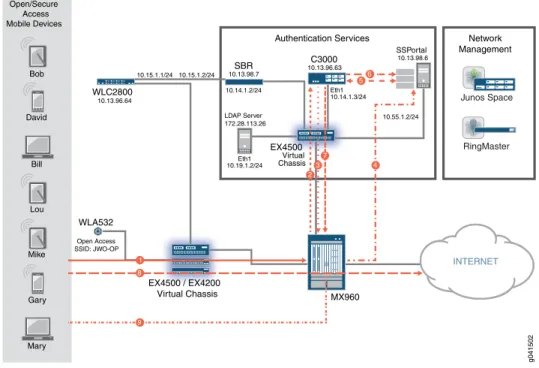
Figure 1: Open Wi-Fi Access Operation Using a Captive Portal
Bob David Bill Lou Mike Gary Mary Open/Secure Access Mobile Devices 10.15.1.1/24 10.15.1.2/24 10.13.96.64 WLC2800 WLA532 MX960 INTERNET EX4500 / EX4200 Virtual Chassis Open Access SSID: JWO-OP Eth1 10.14.1.3/24 Eth1 10.19.1.2/24 LDAP Server 172.28.113.26 10.55.1.2/24 10.14.1.2/24 C3000 10.13.96.63 SBR 10.13.98.7 SSPortal 10.13.98.6 Authentication Services 56 7 4 9 8 1 EX4500 Virtual Chassis 37 2 g041502 RingMaster Junos Space Network Management
The following steps describe the operation of the open scenario in general terms. This is not intended to be an exhaustive engineering specification.Figure 1 on page 4illustrates these steps:
1. The user’s mobile device connects through the WLA532 using the JWO-OP SSID and initiates a DHCP request.
2. The DHCP request triggers the MX Series router to start the provisioning process by sending a JSRC-AA request to the SRC running on the C3000 Controller.
3. Since the subscriber is not present in the Session State Registrar (SSR), the user is an unauthenticated subscriber, and the SRC returns the Open-Portal default profile to the MX Series router. The Open-Portal default profile limits the connection to only a captive portal.
4. The DHCP service running on the MX Series router provides an IPv4 address to the mobile device, the user session is redirected to the captive portal on the sample residential portal (SSPortal) application, and the subscriber provides his user credentials to log in to the portal.
5. The SSPortal verifies the credentials with the C3000 Controller.
6. The user is authenticated.
8. The MX Series router applies the Internet service policy to the user session, and the user accesses the Internet.
9. The user session disconnects after the idle timeout period.
Operation of Secure Wi-Fi Access Using EAP Authentication
This section describes the scenario for secure Wi-Fi access to the Internet using EAP authentication. It presents the call flow and explains the role that each device plays in the topology.
EAP-based access is an automated authentication process between the mobile device and the Authentication, Authorization, and Accounting (AAA) server on the network. Software on the mobile device negotiates with the AAA server and agrees on the manner in which credentials are exchanged with the network. Authentication occurs during the Wi-Fi attachment, and once connected the user has his subscribed network access. InFigure 2 on page 6:
• The Juniper Networks WLA532 Wireless LAN Access Point provides wireless access to the mobile users.
• The Juniper Networks WLC2800 Wireless LAN Controller controls the configuration of the WLAs.
• The Juniper Networks EX Series Ethernet Switches are configured in a virtual chassis to provide Layer 2 connectivity. Members zero and three of the virtual chassis are EX4500 switches, and member one and two are EX4200 switches.
• The Juniper Networks C3000 Controller is running the Series Session and Resource Control Modules to provide session control.
• The MX960 router provides broadband network gateway (BNG) functionality.
• In your network it is assumed that there is some amount of Layer 2 and Layer 3 infrastructure between the MX Series router and the Internet. In this example, the additional infrastructure is not shown.
• The Steel-Belted Radius (SBR) server provides AAA services.
• The SSPortal does not participate in the secure access scenario.
• The Juniper Networks Junos Space application and Juniper Networks RingMaster Appliance are shown for reference but are not described in this example.
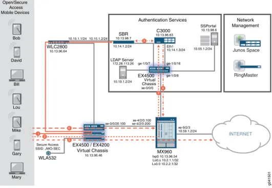
Figure 2: Secure Wi-Fi Access Operation Using EAP Authentication
Bob David Bill Lou Mike Gary Mary Open/Secure Access Mobile Devices 10.13.96.64 INTERNET EX4500 / EX4200 Virtual Chassis WLA532 SBR 10.13.98.7 Secure Access SSID: JWO-SEC ge-1/0/8 ge-1/0/16 ge-1/0/7 Eth1 10.14.1.3/24 10.19.1.2/24 xe-0/0/20.100 xe-4/2/0.200 10.59.1.2/24 xe-4/2/0.100 xe-9/2/3 LDAP Server 172.28.113.26 10.15.1.1/24 10.15.1.2/24 10.55.1.2/24 C3000 10.13.96.63 SSPortal 10.13.98.6 10.14.1.2/24 MX960 Lo0.0 10.2.2.1/32 Lo0.o 10.2.1.1/32 fxp0 10.13.96.54 10.13.96.46 Authentication Services 5 2 3 xe-0/0/0 EX4500 Virtual Chassis 4 2 WLC2800 6 g041501 1 RingMaster Junos Space Network ManagementThe following steps describes the operation of the secure scenario in general terms. This is not intended to be an exhaustive engineering specification.Figure 2 on page 6illustrates these steps:
1. The user’s mobile device connects through the WLA532 using the JWO-SEC SSID. The WLC2800 exchanges messages between the mobile device and the SBR AAA server. The mobile device and the SBR AAA server agree on the EAP type (EAP-PEAP in this example), and the mobile device presents credentials. The SBR sends a message to the WLC to allow the mobile device and updates the Session State Registrar (SSR).
2. The WLC forwards the DHCP request from the mobile device to the MX Series BNG, and the MX Series router sends a JSRC-AA request to the SRC running on the C3000 Controller to determine the appropriate policy for the subscriber.
3. The SRC sends a Lightweight Directory Access Protocol (LDAP) request to the SBR that includes the MAC address of the mobile device. The SRC retrieves the username, calling station’s ID, and service bundle.
4. The SRC pushes the Internet policy to the MX Series router.
5. The user accesses the Internet.
6. The user session disconnects after the idle timeout period. Related
Documentation
Service Provider Wi-Fi Drivers on page 1
•
• Example: Configuring Open Wi-Fi Access to the Internet Using a Captive Portal and Secure Wi-Fi Access to the Internet Using EAP Authentication on page 7
Example: Configuring Open Wi-Fi Access to the Internet Using a Captive Portal and
Secure Wi-Fi Access to the Internet Using EAP Authentication
This example provides step-by-step procedures to configure open Wi-Fi access to the Internet using a captive portal and secure Wi-Fi access to the Internet using EAP authentication. • Requirements on page 7 • Overview on page 7 • Configuration on page 9 • Verification on page 41
Requirements
This example uses the following hardware and software components:
• One Juniper Networks MX Series 3D Universal Edge Router running Junos OS Release 11.4 or later.
• Four Juniper Networks EX4200 Ethernet Switches or EX4500 Ethernet Switches configured as virtual chassis and running Junos OS Release 11.4 or later.
• One Juniper Networks WLC2800 Wireless LAN Controller running Mobility System Software (MSS) Release 7.7 (MR1) or later.
• Two Juniper Networks WLA532 Wireless LAN Access Points. There are no software requirements.
• One Juniper Networks C3000 Controller running Juniper Networks Session and Resource Control (SRC) portfolio Release 4.2.0 R1 or later.
• One SSPortal application running Release 4.2.0 R1 or later running on Oracle Solaris 10 9/10.
• One Steel-Belted Radius (SBR) server running SBR Carrier Standalone Release 7.4.1.R-0.225283 or later on Oracle Solaris 10 9/10.
NOTE:This configuration example has been tested using the software release listed and is assumed to work on all later releases.
Overview
In this example, two WLA532 access points provide Wi-Fi service to mobile users. The WLC2800 controller is the single point of control for the WLAs.
The EX Series switches are configured as a virtual chassis. The first three EX Series switches in the virtual chassis provide Layer 2 connectivity from the WLA532 access points to the WLC2800 Wireless LAN Controller and between the WLC2800 controller and the MX Series router. The fourth EX Series switch in the virtual chassis connects the MX Series router to the C3000 Controller.
The MX Series router is providing Dynamic Host Configuration Protocol (DHCP) services and Juniper Session and Resource Control services.
The Steel-Belted Radius server is providing authentication, authorization, and accounting (AAA) services using the Extensible Authentication Protocol (EAP).
The C3000 Controller is providing Session and Resource Control (SRC) services. The SSPortal is a sample residential portal application provided by Juniper Networks. The sample residential portal application is used for testing purposes in this example. The physical topology is shown inFigure 3 on page 8.
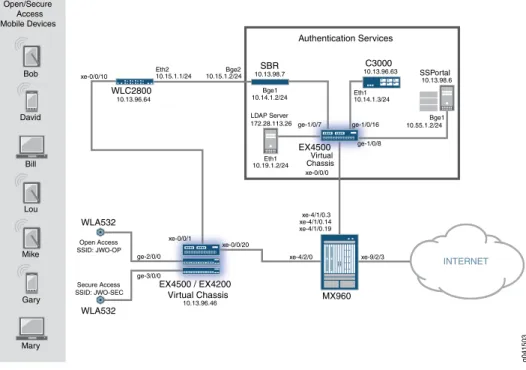
Figure 3: Carrier Wi-Fi Access Supporting Open and Secure Wi-Fi Access
Logical Topology
Bob David Bill Lou Mike Gary Mary Open/Secure Access Mobile Devices 10.13.96.64 WLC2800 WLA532 MX960 INTERNET Authentication Services EX4500 / EX4200 Virtual Chassis WLA532 SBR 10.13.98.7 Open Access SSID: JWO-OP Secure Access SSID: JWO-SEC ge-1/0/7 10.14.1.3/24 10.19.1.2/24 10.19.1.1/24 10.14.1.1/24 10.55.1.1/24 Lo0.0 10.2.2.1/32 Lo0.0 10.2.1.1/32 fxp0 10.13.96.54 10.59.1.2/24 g041500 LDAP Server 172.28.113.26 10.15.1.1/24 10.15.1.2/24 10.55.1.2/24 10.14.1.2/24 10.13.98.6 SSPortal C3000 10.13.96.63 EX4500 Virtual Chassis RingMaster Junos Space Network ManagementFigure 4: Carrier Wi-Fi Access Supporting Open and Secure Wi-Fi Access
Physical Topology
10.13.96.46 ge-2/0/0 ge-3/0/0 10.13.96.64 WLC2800 WLA532 MX960 INTERNET EX4500 / EX4200 Virtual Chassis WLA532 SBR 10.13.98.7 Open Access SSID: JWO-OP Secure Access SSID: JWO-SEC xe-0/0/0 ge-1/0/8 ge-1/0/16 ge-1/0/7 Eth1 10.14.1.3/24 Eth1 10.19.1.2/24 xe-0/0/20 xe-0/0/1 xe-0/0/10 xe-4/1/0.19 xe-4/1/0.14 xe-4/1/0.3 xe-4/2/0 xe-9/2/3 LDAP Server 172.28.113.26 Eth2 10.15.1.1/24 10.15.1.2/24Bge2 Bge1 10.55.1.2/24 10.13.98.6 SSPortal EX4500 Virtual Chassis C3000 10.13.96.63 Bge1 10.14.1.2/24 Authentication Services Bob David Bill Lou Mike Gary Mary Open/Secure Access Mobile Devices g041503For more information about the operation of this example, seeService Provider Wi-Fi DriversandService Provider Wi-Fi Services Supporting Open and Secure Access.
Configuration
To configure this example, perform the following procedures:
NOTE: In any configuration session it is a good practice to periodically use the commit check command to verify that the configuration can be committed.
• Configuring the Wireless LAN Controller System Settings on page 10
• Configuring the Wireless LAN Controller VLANs on page 12
• Configuring the Wireless LAN Controller Interfaces on page 13
• Configuring the Wireless LAN Controller Service Profiles on page 14
• Configuring the Wireless LAN Controller Radio Profiles on page 15
• Adding the WLA532 Access Points on page 15
• Configuring the Wireless LAN Controller Authentication and Authorization on page 16
• Creating Authentication Profiles on the Wireless LAN Controller on page 17
• Configuring the MX Series Broadband Network Gateway Routing Engines on page 17
• Configuring the MX Series Router Physical, Logical, and Demultiplexing Interfaces on page 18
• Configuring the MX Series Broadband Network Gateway Firewall Filters for Open Access on page 19
• Configuring the MX Series Broadband Network Gateway Web Portal Routing Instance for Open Access on page 21
• Configuring the MX Series Broadband Network Gateway Dynamic Profiles for Open Access on page 21
• Configuring the MX Series Router Local DHCP Services and DHCP Address Assignment Pool on page 22
• Configuring the MX Series Router Diameter Protocol on page 23
• Configuring the MX Series Router JSRC Environment on page 24
• Configuring the MX Series Router Access Profile for the Diameter Protocol on page 25
• Configuring the MX Series Broadband Network Gateway Dynamic Profiles for Secure Access on page 26
• Configuring the MX Series Router Broadband Network Gateway Firewall Filters for Secure Access on page 27
• Configuring the MX Series Broadband Network Gateway Web Portal Routing Instance for Secure Access on page 28
• Configuring the EX Series Switch Physical Interfaces on page 29
• Configuring the SSPortal and Enabling Local Authentication on page 30
• Configuring the C3000 Controller to Provide Series Session and Resource Control for Open Access on page 32
• Configuring the C3000 Controller to Send LDAP Queries to the SBR on page 35
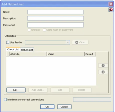
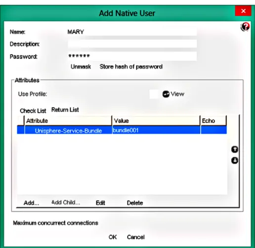
• Adding a Native User to the SBR Server on page 37
Configuring the Wireless LAN Controller System Settings
Step-by-Step Procedure
In this procedure you configure the Juniper Networks WLC2800 Wireless LAN Controller through a serial port. For information about connecting a serial port to the WLC, see the
Wireless LAN Controllers Quick Start Guide. After eachsetcommand is entered, the system displays:success: change accepted.
Before you begin, physically install the wireless LAN access points, wireless LAN controller, routers, and switches as shown in the physical topology illustration.
NOTE: You must have a basic familiarity with Mobility System Software (MSS), the operating system on the WLC, before you begin configuring it. The CLI hierarchy is different from Junos OS. See the Mobility System Software Quick Start Guide.
1. Configure the WLC IPv4 address.
Specify10.15.1.1as the IPv4 address and255.255.255.0as the subnet mask. The 10.15.1.1IPv4 address is used to communicate with the SBR server shown in the example network illustration.
WLC#set system ip 10.15.1.1 255.255.255.0
2. Configure the WLC system name.
SpecifyMOB-WO-64as the name. The name is useful to distinguish the WLC from other devices on the network.
WLC#set system name MOB-WO-64
3. Configure the WLC country code.
SpecifyUSas the country for this example. Wireless networks are subject to regulatory parameters based on the country code where the WLCs and WLAs are physically located, so you must set the country code.
MOB-WO-64#set system countrycode US
4. Configure the WLC enable password.
Specifyjollyrogeras the password for this example. The password is necessary to ensure that only administrators with the enable password can make configuration changes.
MOB-WO-64#set enable password jollyroger
5. Configure the admin user to use an encrypted password on the WLC.
Specifyadminas the user name andencryptedas the password type. Specifydefault as the VLAN theadminuser is associated with. VLAN 1 is nameddefaultby default. Theencryptedoption indicates that the enable password string you entered is already in its encrypted form.
MOB-WO-64#set user admin password encrypted MOB-WO-64#set user admin attr vlan-name default
6. Create a static route to the EX4500 switch.
Specify10.13.98.0as the destination subnet,255.255.255.0as the subnet mask, 10.13.96.1as the next hop router, and2as the distance. Also create a static route to the172.0.0.0subnet for communication with the network management applications.
MOB-WO-64#set ip route 10.13.98.0 255.255.255.0 10.13.96.1 2 MOB-WO-64#set ip route 172.0.0.0 255.0.0.0 10.13.96.1 1
7. Enable telnet access to the WLC.
MOB-WO-64#set ip telnet server enable
8. As a best practice, save your configuration before proceeding. MOB-WO-64#save config
Configuring the Wireless LAN Controller VLANs
Step-by-Step Procedure
In this procedure you configure virtual LANs (VLANs). A VLAN is a Layer 2 broadcast domain that can span multiple wired or wireless LAN segments. When a user successfully authenticates to the network, the user is assigned to a specific VLAN.
Each VLAN is given a VLAN name, associated with a port (interface), and configured with a tag.
NOTE: By default VLAN 1 is assigned the namedefault. If you use a tag value, we recommend that you use the same value as the VLAN number. MSS does not require the VLAN number and tag value to be the same, but other vendors’ devices might require it.
1. Configure VLAN 1.
Specify port1. VLAN 1 maps to interface 1 with the IPv4 address 10.13.96.64. MOB-WO-64#set vlan 1 port 1
2. Configure VLAN 2.
Specify port2. Specifysbras the VLAN name. VLAN 2 maps to interface 2 with the IP address 10.15.1.1. In this example VLAN2 does not require a tag.
MOB-WO-64#set vlan 2 name sbr MOB-WO-64#set vlan 2 port 2
3. Configure VLAN 10.
Specify port10. Specifywlan-1as the VLAN name and specify10as the VLAN tag. VLAN 10 maps to interface 10 with the IP address 192.168.10.2.
MOB-WO-64#set vlan 10 name wlan-1 MOB-WO-64#set vlan 10 port 10 tag 10
4. Configure VLAN 100.
Specify port10. Specifywo-mxas the VLAN name, and specify100as the VLAN tag. VLAN 100 maps to interface 100 with the IP address 10.2.1.2.
MOB-WO-64#set vlan 100 name wo-mx MOB-WO-64#set vlan 100 port 10 tag 100
5. Configure VLAN 20.
Specify port10. Specifywla-2as the VLAN name, and specify20as the VLAN tag. VLAN 20 maps to interface 20 with the IP address 192.168.20.2.
MOB-WO-64#set vlan 20 name wla-2 MOB-WO-64#set vlan 20 port 10 tag 20
6. Configure VLAN 200.
Specify port10. Specifywo-mx-2as the VLAN name, and specify200as the VLAN tag. VLAN 200 maps to interface 200 with the IP address 192.168.20.2.
MOB-WO-64#set vlan 200 name wo-mx-2 MOB-WO-64#set vlan 200 port 10 tag 200
Configuring the Wireless LAN Controller Interfaces
Step-by-Step Procedure
In this procedure you must configure six separate interfaces on the WLC.
One interface is the management interface with the IP address 10.13.96.64. Two interfaces disable the internal DHCP server on the WLC for a block of IP addresses. This is necessary because the MX Series router is acting as the DHCP server and is providing IP addresses to the WLAs. Two more interfaces are used to send network traffic to the MX Series router.
1. Configure the first interface.
Specify10.13.96.64as the IPv4 address and255.255.255.0as the subnet mask. MOB-WO-64#set interface 1 ip 10.13.96.64 255.255.255.0
2. Configure the second interface.
Specify10.15.1.1as the IPv4 address and255.255.255.0as the subnet mask. The second interface communicates with devices on the10.15.1.0subnet.
MOB-WO-64#set interface 2 ip 10.15.1.1 255.255.255.0
3. Configure interface 10.
Specify10as the interface number,192.168.10.2as the IPv4 address, and 255.255.255.0as the subnet mask.
Disable the internal DCHP server for a range of addresses and block out the range of IP addresses used by the MX Series router. Specifydisableto disable the DHCP server, specify192.168.10.10as the starting address in the range of addresses to block and192.168.10.254as the ending address, and specify192.168.10.1(EX Series device) as the DHCP client default router.
You must set the default route in this command to prevent the WLC from sending the static route previously configured to the DHCP client to use.
MOB-WO-64#set interface 10 ip 192.168.10.2 255.255.255.0
MOB-WO-64#set interface 10 ip dhcp-server disable start 192.168.10.10. stop 192.168.10.254 default-router 192.168.10.1
4. Configure interface 100.
Specify100as the interface number,10.2.1.2as the IPv4 address, and255.255.255.0 as the subnet mask.
Specifydisableto disable the DHCP server, and specify192.168.1.10as the starting address in the range of addresses to block and192.168.1.254as the ending address.
MOB-WO-64#set interface 100 ip 10.2.1.2 255.255.255.0
MOB-WO-64#set interface 100 ip dhcp-server disable start 192.168.1.10. stop 192.168.1.254
5. Configure the two interfaces that communicate with the EX Series switch and the MX Series router.
MOB-WO-64#set interface 20 ip 192.168.20.2 255.255.255.0 MOB-WO-64#set interface 200 ip 10.2.2.2 255.255.255.0
Configuring the Wireless LAN Controller Service Profiles
Step-by-Step Procedure
In this procedure you configure service profiles. A service profile controls advertisement and encryption for a service set identifier (SSID).
1. Configure a service profile to create an encrypted SSID to support the secure access scenario.
SpecifyJWO-EAPas the profile name andJWO-SECas the SSID name. MOB-WO-64#set service-profile JWO-EAP ssid-name JWO-SEC
2. Disable the 802.11n short guard interval on the JWO-EAP service profile.
The short guard interval prevents inter-symbol interference on an 802.11n network. Leaving the short guard interval enabled is appropriate for home-use deployments.
MOB-WO-64#set service-profile JWO-EAP 11n short-guard-interval disable
3. Enable the Wi-Fi Protected Access (WPA) information element in the service profile, and enable Temporal Key Integrity Protocol (TKIP) encryption for Robust Security Network (RSN) or WPA clients.
MOB-WO-64#set service-profile JWO-EAP wpa-ie cipher-tkip enable MOB-WO-64#set service-profile JWO-EAP wpa-ie enable
4. Add a VLAN to the service profile. Specifywo-mx-2as the VLAN name.
MOB-WO-64#set service-profile JWO-EAP attr vlan-name wo-mx-2
5. Configure a service profile to create an open access SSID.
SpecifyOpenas the profile name andJWO-OPas the SSID name. Also configure the SSID type asclear.
MOB-WO-64#set service-profile Open ssid-name JWO-OP MOB-WO-64#set service-profile Open ssid-type clear
6. Configure the open service profile to automatically authenticate the user and allow access to the SSID requested by the user without a username and password. Specifylast-resortas the authentication fall-through behavior.
MOB-WO-64#set service-profile Open auth-fallthru last-resort
7. Disable the 802.11n short guard interval on the open service profile.
The short guard interval prevents inter-symbol interference on an 802.11n network. Leaving the short guard interval enabled is appropriate for home-use deployments.
MOB-WO-64#set service-profile Open 11n short-guard-interval disable
8. Disable encryption on the open service profile.
MOB-WO-64#set service-profile Open wpa-ie auth-dot1x disable MOB-WO-64#set service-profile Open rsn-ie auth-dot1x disable
9. Add the VLAN on the open service profile. Specifywo-mxas the VLAN name.
MOB-WO-64#set service-profile Open attr vlan-name wo-mx
Configuring the Wireless LAN Controller Radio Profiles
Step-by-Step Procedure
In this procedure you configure radio profiles. A radio profile is a set of parameters that apply to multiple radios. You can assign configuration parameters to many radios by configuring a profile and assigning the profile to the radios. Radio profiles then map to service profiles.
1. Create a radio profile namedJWO-1. MOB-WO-64#set radio-profile JWO-1
2. Configure the radio profile channel width. Specify20MHzas the width.
MOB-WO-64#set radio-profile JWO-1 11n channel-width-na 20MHz
3. Map the radio profile to theOpenservice profile.
MOB-WO-64#set radio-profile JWO-1 service-profile Open
4. Create a radio profile namedJWO-2and map it to theJWO-EAPsecure service profile.
MOB-WO-64#set radio-profile JWO-2
MOB-WO-64#set radio-profile JWO-2 11n channel-width-na 20MHz MOB-WO-64#set radio-profile JWO-2 service-profile JWO-EAP
Adding the WLA532 Access Points
Step-by-Step Procedure
In this procedure you configure the WLC2800 to identify the WLA532s by serial number, apply a name and description to the access points, and apply the radio profiles.
1. Disable the automatic Distributed WLA configuration type. MOB-WO-64#set ap auto mode disable
2. Disable the requirement for encryption keys from the WLA532s. MOB-WO-64#set ap security none
3. Configure the WLC2800 to identify the first WLA532 connected to port 1 by serial number.
In this example, specify1as the Distributed WLA number,jb0212247313as the serial number, andWLA532-USas the model number.
NOTE: In your network, use the serial number located on the back of your WLA for this step.
MOB-WO-64#set ap 1 serial-id jb0212247313 model WLA532-US
4. Configure a name and description for the WLA. MOB-WO-64#set ap 1 name WO-1
MOB-WO-64#set ap 1 description WiFi Offload
5. Apply the radio profile for the WLA.
Specify1for the first radio in the WLC532, and specify2for the second radio. Specify JWO-1as the profile andenableas the mode for both radios.
MOB-WO-64#set ap 1 radio 1 radio-profile JWO-1 mode enable MOB-WO-64#set ap 1 radio 2 radio-profile JWO-1 mode enable
6. Configure the WLC2800 to identify the second WLA532 connected to port 2.
NOTE: In your network, use the serial number located on the back of your WLA for this step.
MOB-WO-64#set ap 2 serial-id jb0212248475 model WLA532-US MOB-WO-64#set ap 2 name WO-2
MOB-WO-64#set ap 2 description WiFi Offload
MOB-WO-64#set ap 2 radio 1 radio-profile JWO-2 mode enable MOB-WO-64#set ap 2 radio 2 radio-profile JWO-2 mode enable
Configuring the Wireless LAN Controller Authentication and Authorization
Step-by-Step Procedure
In this procedure you configure the RADIUS client on the WLC. Configure the RADIUS client with the system IPv4 address.
1.
Doing this causes the RADIUS client to use the IPv4 address specified in theset system ip-addresscommand as the source address in the request packets sent to the server.
MOB-WO-64#set radius client system-ip
2. Configure the RADIUS client and attributes.
Specifysol.mob.sbras the server name. Specify10.15.1.2as the IPv4 address of the RADIUS server.
Specify5seconds as the time the RADIUS client waits for a response from the RADIUS server before retransmitting. Specify3as the number of transmission attempts before declaring an unresponsive RADIUS server unavailable. Specify5 as the number of minutes the WLC waits after declaring an unresponsive RADIUS server unavailable before retrying that RADIUS server.
Specify09404f0b485744as the encrypted shared secret key. The key will be different on your network. SpecifyUSE-MAC-ADDRESSto send the user MAC address as the password used for authorization to a RADIUS server for MAC authentication.
MOB-WO-64#set radius server sol.mob.sbr address 10.15.1.2 timeout 5 retransmit 3 deadtime 5 encrypted-key 09404f0b485744 author-password
USE-MAC-ADDRESS
3. Configure the RADIUS client to use the colon separated format for the MAC address used for the password.
Specifycolonsas the format.
MOB-WO-64#set radius server sol.mob.sbr mac-addr-format colons
4. Configure the RADIUS client with a server group name and group member name. Specifysol.mob.sbr-groupas the group name and specifysol.mob.sbras a member server name.
MOB-WO-64#set server group sol.mob.sbr-group members sol.mob.sbr
Creating Authentication Profiles on the Wireless LAN Controller
Step-by-Step Procedure
In this procedure you create AAA profiles that use 802.1X authentication.
Enable command accounting for the secure users authenticated by the dot1x authentication method.
1.
Specifydot1xto audit the users who are authenticated by the dot1x method. Specify JWO-SECas the SSID name to which this accounting rule applies. Specify**to match all usernames.
MOB-WO-64#set accounting dot1x ssid JWO-SEC ** start stop sol.mob.sbr-group
2. Enable authentication auditing for the secure users authenticated by the dot1x authentication method.
Specifydot1xto audit the users who are authenticated by the dot1x method. Specify JWO-SECas the SSID name to which this accounting rule applies. Specify**to match all usernames.
MOB-WO-64#set authentication dot1x ssid JWO-SEC ** pass-through sol.mob.sbr-group
Configuring the MX Series Broadband Network Gateway Routing Engines
Step-by-Step Procedure
In this procedure you configure the MX Series dual Routing Engines using a Junos OS command line interface.
The MX Series router plays a central role in this configuration. The MX Series router is providing Dynamic Host Configuration Protocol (DHCP) services and Juniper Session and Resource Control services. Think of the MX Series router as the gatekeeper for Internet access.
1. Configure a hostname on each Routing Engine. [edit]
user@host#set groups re0 system host-name sol-mob-54 user@host#set groups re1 system host-name sol-mob-55
2. Configure an IP address and protocol family on thefxp0management interface for each Routing Engine.
[edit]
user@host#set groups re0 interfaces fxp0 unit 0 family inet address 10.13.96.54/24 user@host#set groups re1 interfaces fxp0 unit 0 family inet address 10.13.96.55/24
3. Configure the router to automatically load and commit the configuration on both Routing Engines.
[edit]
user@host#set system commit synchronize
4. Apply the group configuration for each Routing Engine. [edit]
user@host#set apply-groups re0 user@host#set apply-groups re1
Configuring the MX Series Router Physical, Logical, and Demultiplexing Interfaces
Step-by-Step Procedure
In this procedure you configure the physical and logical interfaces on the MX Series router. Enable VLAN tagging on thexe-4/1/010-Gigabit Ethernet physical interface and optionally add a description.
1.
[edit]
user@host#set interfaces xe-4/1/0 vlan-tagging
user@host#set interfaces xe-4/1/0 description "CONNECTED TO EX4500-46"
2. Configure an IPv4 address and protocol family on the logical interfaces under the xe-4/1/0physical interface, specify theinetprotocol family, and assign a VLAN ID.
[edit]
user@host#set interfaces xe-4/1/0 unit 3 family inet address 10.55.1.1/24 user@host#set interfaces xe-4/1/0 unit 3 vlan-id 3
user@host#set interfaces xe-4/1/0 unit 14 family inet address 10.14.1.1/24 user@host#set interfaces xe-4/1/0 unit 14 vlan-id 14
user@host#set interfaces xe-4/1/0 unit 19 family inet address 10.19.1.1/244 user@host#set interfaces xe-4/1/0 unit 19 vlan-id 19
3. Enable VLAN tagging on thexe-4/2/010-Gigabit Ethernet physical interface and optionally add a description.
[edit]
user@host#set interfaces xe-4/2/0 vlan-tagging
user@host#set interfaces xe-4/2/0 description "CONNECTED TO EX-AP1"
4. Configure logical interface100under thexe-4/2/0physical interface.
Specify theinetprotocol family and configure the interface to use either the preferred 10.2.1.1address or an unnumbered IPv4 address derived from thelo0.0loopback interface. Also assign a VLAN ID.
[edit]
user@host#set interfaces xe-4/2/0 unit 100 family inet unnumbered-address lo0.0 preferred-source-address 10.2.1.1
user@host#set interfaces xe-4/2/0 unit 100 demux-source inet user@host#set interfaces xe-4/2/0 unit 100 vlan-id 100
5. Configure logical interface200under thexe-4/2/0physical interface.
Specify theinetprotocol family and configure the interface to use either the preferred 10.2.2.1address or an unnumbered IPv4 address derived from thelo0.0loopback interface. Also assign a VLAN ID.
[edit]
user@host#set interfaces xe-4/2/0 unit 200 family inet unnumbered-address lo0.0 preferred-source-address 10.2.2.1
user@host#set interfaces xe-4/2/0 unit 200 demux-source inet user@host#set interfaces xe-4/2/0 unit 200 vlan-id 200
6. Create the logical demultiplexing (demux) interface.
Configure the demux source family address type on the IP demux underlying interface under thexe-4/2/0physical interface and unit100logical interface. Specify theinet family to use IPv4 as the address family for the demux interface source address.
[edit]
user@host#set interfaces xe-4/2/0 unit 100 demux-source inet
7. Configure the Routing Engine loopback logical interfaces.
Specifylo0as the loopback interface and0as the logical interface number. Specify theinetaddress family. Configure the interface to use10.2.1.1as the primary IPv4 address and10.2.2.1as a secondary address.
[edit]
user@host#set interfaces lo0 unit 0 family inet address 10.2.1.1/32 primary user@host#set interfaces lo0 unit 0 family inet address 10.2.2.1/32
Configuring the MX Series Broadband Network Gateway Firewall Filters for Open Access
Step-by-Step Procedure
In this procedure you configure firewall filters on the MX Series router to support the open access scenario. Firewall filters are used in this scenario to redirect the HTTP traffic to the routing instance of the captive Web portal and to account for the traffic that is ICMP, Proxy HTTP, HTTP, or discarded.
1. Create a firewall filter.
Specifymyifd-xe-4/2/0.100as the name and include theinterface-specificoption. Theinterface-specificoption is used to configure firewall counters that are specific to interfaces. Theinetaddress family is applied by default and not explicitly configured.
[edit]
user@host#set firewall filter myifd-xe-4/2/0.100 interface-specific
2. Configure the first term in the firewall filter.
Specify6as the term name andicmpas the protocol to match. Configure the term to count the ICMP packets and write the information to a counter namedicmpcount. Also configure the terminating action toacceptthe packets.
[edit]
user@host#set firewall filter myifd-xe-4/2/0.100 term 6 from protocol icmp user@host#set firewall filter myifd-xe-4/2/0.100 term 6 then count icmpcount
user@host#set firewall filter myifd-xe-4/2/0.100 term 6 then accept
3. Configure the second term in the firewall filter.
Specify1as the term name. Configure the term to match packets that are tagged with theservice-filter-hitaction. Also configure the terminating action toacceptthe packets. The packet can be tagged with theservice-filter-hitaction by the RADIUS server.
Theservice-filter-hitaction is used to effectively bypass unnecessary filters when there are filter chains.
[edit]
user@host#set firewall filter myifd-xe-4/2/0.100 term 1 from service-filter-hit user@host#set firewall filter myifd-xe-4/2/0.100 term 1 then accept
4. Configure the third term in the firewall filter.
This is the term that redirects Web browser traffic to the captive portal.
Specify2as the term name. Configure the term to match the destination TCP port 80(HTTP). Configure the term to count the packets and write the information to a counter namedport80count, and then send the packets to the routing instance namedweb-portal.
[edit]
user@host#set firewall filter portal-filter term 2 from destination-port 80 user@host#set firewall filter portal-filter term 2 then count port80count
user@host#set firewall filter portal-filter term 2 then routing-instance web-portal
5. Configure the next term in the firewall filter.
Specify3as the term name. Specifydomainto match packets with the DNS destination TCP port. Also configure the terminating action toacceptthe packets.
[edit]
user@host#set firewall filter portal-filter term 3 from destination-port domain user@host#set firewall filter portal-filter term 3 then accept
6. Configure the next term in the firewall filter.
Specify4as the term name. Configure the term to match the destination TCP port 8080(proxy HTTP). Configure the term to count the packets, write the information to a counter namedport8080count, and thenacceptthe packets.
[edit]
user@host#set firewall filter portal-filter term 4 from destination-port 8080 user@host#set firewall filter portal-filter term 4 then count port8080count user@host#set firewall filter portal-filter term 4 then accept
7. Configure the final term in the firewall filter.
Specify5as the term name. Configure the term to count the packets, write the information to a counter nameddiscardcount, and thendiscardthe packets.
[edit]
user@host#set firewall filter portal-filter term 5 then count discardcount user@host#set firewall filter portal-filter term 5 then discard
Configuring the MX Series Broadband Network Gateway Web Portal Routing Instance for Open Access
Step-by-Step Procedure
In this procedure you configure the routing instance that provides the route to the captive Web portal.
1. Download the SSPortal.war file from the following URL:
https://download.juniper.net/software/sdx/src-pe-4.4.0/SDK+AppSupport+Demos+Samples.tar.gz
2. Untar the package and copy thessportal.warfile to the deploy directory. user@host>cp
../SDK+AppSupport+Demos+Samples/DemosAndSamplesApplications/webapps/ssportal.war /export/home0/jboss-6.1.0.Final/server/all/deploy
3. Configure a routing instance namedweb-portaland specify theforwardinginstance type.
[edit]
user@host#set routing-instances web-portal instance-type forwarding
4. Configure a static route that matches all IPv4 addresses and specify10.55.1.2as the next hop.
The 10.55.1.2 address is configured on the Ethernet interface on the SSPortal server. [edit]
user@host#set routing-instances web-portal routing-options static route 0.0.0.0/0 next-hop 10.55.1.2
5. Configure the router to retain the static route in the event that the routing process shuts down.
[edit]
user@host#set routing-instances web-portal routing-options static route 0.0.0.0/0 retain
Configuring the MX Series Broadband Network Gateway Dynamic Profiles for Open Access
Step-by-Step Procedure
In this procedure you configure a default dynamic profile on the MX Series router for the open access scenario. Dynamic profiles are a template that defines a set of characteristics that are combined with authorization attributes and are dynamically assigned to static interfaces to provide dynamic subscriber access and services for broadband applications.
1. Create a dynamic profile and specify the variables.
Specifydemux-default-open-accessas the name and include the $junos-interface-unitvariable.
The variables enable dynamic association of certain interface-specific values to incoming subscriber requests. When a client accesses the router, the dynamic profile configuration replaces the predefined variable with the actual data from an incoming client data packet and from configuration. The$junos-interface-unitvariable is dynamically replaced with the logical interface unit number that DHCP supplies when the subscriber logs in. The$junos-underlying-interfacevariable is dynamically
replaced with the underlying interface that DHCP supplies when the subscriber logs in. A demux interface uses an underlying logical interface to receive packets.
[edit]
user@host#set dynamic-profiles demux-default-open-access interfaces demux0 unit "$junos-interface-unit" demux-options underlying-interface
"$junos-underlying-interface"
2. Configure the demultiplexing (demux) interface used in the dynamic profile. To identify subscribers dynamically, you specify variable values that are dynamically determined when subscribers log in.
Specifydemux-default-open-accessas the demux interface name. Specify $junos-interface-unitas the logical interface variable. Specify
$junos-subscriber-ip-addressas the demux source address variable for a subscriber in the open access dynamic profile. The IPv4 source address for the interface is dynamically supplied by DHCP when the subscriber accesses the router.
[edit]
user@host#set dynamic-profiles demux-default-open-access interfaces demux0 unit "$junos-interface-unit" family inet demux-source
$junos-subscriber-ip-address
3. Configure the demux interface to derive the local source address from the unnumbered IPv4 addresses of thelo0.0logical loopback interface.
[edit]
user@host#set dynamic-profiles demux-default-open-access interfaces demux0 unit "$junos-interface-unit" family inet unnumbered-address lo0.0
4. Configure the demux interface to dynamically derive the local source address from the preferred source IPv4 address specified.
When you use the dynamic variable, the address that is selected resides in the same network as the IP address of the subscriber, if that address is configured as one of the addresses of the specified interface. Configuring the preferred source address enables you to use an IP address other than the primary IP address on some of the unnumbered Ethernet interfaces in your network.
[edit]
user@host#set dynamic-profiles demux-default-open-access interfaces demux0 unit "$junos-interface-unit" family inet unnumbered-address
preferred-source-address 10.2.1.1
Configuring the MX Series Router Local DHCP Services and DHCP Address Assignment Pool
Step-by-Step Procedure
In this procedure you configure a local DHCP service for each group of clients. The subscriber access feature requires that a subscriber such as a DHCP client send a discover message to the router interface to initialize dynamic configuration of that interface. You also configure a local DHCP server address assignment pool. The address pool can be used by different client applications.
Specify that the DHCP local server is enabled on the dynamic profile named demux-default-open-access, thexe-4/2/0interface, and the100VLAN identifier.
[edit]
user@host#set system services dhcp-local-server group Open-Subs dynamic-profile demux-default-open-access
user@host#set system services dhcp-local-server group Open-Subs interface xe-4/2/0.100
2. Create a DHCP address pool.
SpecifyOpen-Dhcp-Poolas the pool name. Specify theinetfamily and the10.2.1.0 subnet. Also specify the subnet mask length.
[edit]
user@host#set access address-assignment pool Open-Dhcp-Pool family inet network 10.2.1.0/24
user@host#set access address-assignment pool Open-Dhcp-Pool family inet mask-length 32
3. Specify the upper and lower range of addresses that can be used in the pool. [edit]
user@host#set access address-assignment pool Open-Dhcp-Pool family inet range r1 low 10.2.1.10
user@host#set access address-assignment pool Open-Dhcp-Pool family inet range r1 high 10.2.1.100
4. Specify the domain name system (DNS) name server available to the client to resolve hostname-to-client mappings.
In this example the DNS name server is hosted on the same device as the SSPortal. This is equivalent to DHCP option 6. It tells the client the DNS servers it can use.
[edit]
user@host#set access address-assignment pool Open-Dhcp-Pool family inet dhcp-attributes name-server 10.55.1.2
5. Specify a router located in the client’s subnet.
This statement is the equivalent of DHCP option 3. It tells the client a router it can use.
[edit]
user@host#set access address-assignment pool Secure-Dhcp-Pool family inet dhcp-attributes router 10.2.2.1
Configuring the MX Series Router Diameter Protocol
Step-by-Step Procedure
In this procedure you configure the Diameter protocol. The Diameter protocol provides communications between the local Service and Resource Control (SRC) peer on a Juniper Networks routing platform and the remote SRC peer on a Juniper Networks C Series Controller.
1. Configure the origin realm used in protocol messages.
Specifymob.jnpr.netas the realm name. Specifysol-mob-54as the hostname sent in protocol messages. The hostname is supplied as the value for the Origin-Host
AVP by the Diameter instance. The name is used by the administrator. It is not resolved by DNS.
[edit]
user@host#set diameter origin realm mob.jnpr.net user@host#set diameter origin host sol-mob-54
2. Configure the Diameter protocol peer.
Specifymob-src-63as the peer name. Specify1as the peer priority. A peer with a lower number has a higher priority. Also configure10.14.1.3as the peer address and 3868as the TCP port used for active connections to the peer.
[edit]
user@host#set diameter network-element dne1 peer mob-src-63 priority 1 user@host#set diameter peer mob-src-63 address 10.14.1.3
user@host#set diameter peer mob-src-63 connect-actively port 3868
3. Define which destinations are reachable through the Diameter network element. Specifyroute1as the name of the route. Specifyjsrcas the name of the application (function) associated with this Diameter network element anddefaultas the partition associated with the function. Also specifymob.jnpr.netas the destination realm,dne1as the destination hostname, and1as the route metric.
[edit]
user@host#set diameter network-element dne1 forwarding route route1 function jsrc
user@host#set diameter network-element dne1 forwarding route route1 function partition default
user@host#set diameter network-element dne1 forwarding route route1 destination realm mob.jnpr.net
user@host#set diameter network-element dne1 forwarding route route1 destination host dne1
user@host#set diameter network-element dne1 forwarding route route1 metric 1
Configuring the MX Series Router JSRC Environment
Step-by-Step Procedure
In this procedure you configure the Juniper Networks Session and Resource Control environment. JSRC and is part of the AAA application running on the MX Series router. JSRC provides a central administrative point for managing subscribers and their services. JSRC works within a specific logical system:routing instance context, called a partition. JSRC is not an acronym.
1. Create a JSRC partition.
Specifydefaultas the partition name andmasteras the routing instance name. [edit]
user@host#set jsrc-partition default
user@host#set jsrc partition default diameter-instance master
2. Specifymob.jnpr.netas the destination realm used in protocol messages, and specify dne1as the hostname of the destination host that is the service activation engine (SAE).
user@host#set jsrc partition default destination-realm mob.jnpr.net user@host#set jsrc partition default destination-host dne1
Configuring the MX Series Router Access Profile for the Diameter Protocol
Step-by-Step Procedure
In this procedure you configure an access profile for open access. The access profile defines the AAA services and options for subscribers associated with the domain map.
1. Configure the authentication order.
SpecifyJWO-P1as the profile name and specifynoneto grant authentication without examining the client credentials. Configure the provisioning order and specifyjsrc as the application used to communicate with the SAE for subscriber service provisioning.
[edit]
user@host#set access profile JWO-P1 authentication-order none user@host#set access profile JWO-P1 provisioning-order jsrc
2. Configure the session options using one of the following two methods.
• Specify10minutes as the grace period that begins after an authenticated user terminates all sessions and connections. Authentication is not required if a new connection is initiated by the same user during the grace period. Configure the accounting order and specifyactivation-protocolas the method used for reporting subscriber service accounting. Theactivation-protocolstatement causes the router to send service accounting reports by means of the application that activates the services. In this case the service is JSRC.
[edit]
user@host#set access profile JWO-P1 session-options client-idle-timeout 10 user@host#set access profile JWO-P1 service accounting-order
activation-protocol
• If you do not want an authenticated user to be able to reconnect during the grace period, use this alternate configuration. Instead of including theclient-idle-timeout statement, include theclient-session-timeoutstatement. Specify2minutes as the timeout. A user session that is idle for more than 2 minutes is disconnected.
[edit]
user@host#set access profile JWO-P1 session-options client-session-timeout 2
3. Define the access profile to use in the master routing instance by specifyingJWO-P1 as the profile name
[edit]
Configuring the MX Series Broadband Network Gateway Dynamic Profiles for Secure Access
Step-by-Step Procedure
In this procedure you configure dynamic profiles on the MX Series router. Dynamic profiles are a template that defines a set of characteristics that are combined with authorization attributes and are dynamically assigned to static interfaces to provide dynamic subscriber access and services for broadband applications.
1. Create a dynamic profile and specify the variables.
SpecifySecure-EAPas the name and include the$junos-interface-unitvariable. The variables enable dynamic association of certain interface-specific values to incoming subscriber requests. When a client accesses the router, the dynamic profile configuration replaces the predefined variable with the actual data from an incoming client data packet and from the configuration. The$junos-interface-unitvariable is dynamically replaced with the logical interface unit number that DHCP supplies when the subscriber logs in. The$junos-underlying-interfacevariable is dynamically replaced with the underlying interface that DHCP supplies when the subscriber logs in.
[edit]
user@host#set dynamic-profiles Secure-EAP interfaces demux0 unit "$junos-interface-unit" demux-options underlying-interface "$junos-underlying-interface"
2. Configure the logical demux source address for a subscriber in the secure access dynamic-profile.
SpecifySecure-EAPas the demux interface name. Specify$junos-interface-unitas the logical interface variable. Specify$junos-subscriber-ip-addressas the demux source address variable for a subscriber in the open access dynamic profile. The IPv4 source address for the interface is dynamically supplied by DHCP when the subscriber accesses the router.
[edit]
user@host#set dynamic-profiles Secure-EAP interfaces demux0 unit
"$junos-interface-unit" family inet demux-source $junos-subscriber-ip-address
3. Configure the firewall filter used to evaluate packets that are received on the logical demux interface.
Specifyjwo-intas the firewall filter name. [edit]
user@host#set dynamic-profiles Secure-EAP interfaces demux0 unit "$junos-interface-unit" family inet filter input jwo-int
4. Configure the demux interface to derive the local source address from the unnumbered IPv4 address of the lo0.0 logical loopback interface.
[edit]
user@host#set dynamic-profiles Secure-EAP interfaces demux0 unit "$junos-interface-unit" family inet unnumbered-address lo0.0
5. Configure the demux interface to dynamically derive the local source address from the preferred source IPv4 address specified.
When you use the dynamic variable, the address that is selected resides in the same network as the IP address of the subscriber, if that address is configured as one of the addresses of the specified interface. Configuring the preferred source address enables you to use an IP address other than the primary IP address on some of the unnumbered Ethernet interfaces in your network.
[edit]
user@host#set dynamic-profiles Secure-EAP interfaces demux0 unit
"$junos-interface-unit" family inet unnumbered-address preferred-source-address 10.2.2.1
Configuring the MX Series Router Broadband Network Gateway Firewall Filters for Secure Access
Step-by-Step Procedure
In this procedure you configure firewall filters on the MX Series router to support the secure access scenario. Firewall filters are used in this scenario to redirect the HTTP traffic to the routing instance that provides connection to the Internet and to account for the traffic that is ICMP, Proxy HTTP, HTTP, or discarded.
1. Create a firewall filter.
Specifyjwo-intas the name and include theinterface-specificoption. The interface-specificoption is used to configure firewall counters that are specific to interfaces. Theinetaddress family is applied by default and is not explicitly configured.
[edit]
user@host#set firewall filter jwo-int interface-specific
2. Configure the first term in the firewall filter.
Specifyt5as the term name andicmpas the protocol to match. Configure the term to count the packets and write the information to theservice-accountingcounter. Also configure the terminating action toacceptthe packets. When the match conditions for the filter are met, the packet is counted and applied to the well-known service counter (__junos-dyn-service-counter) for use by the RADIUS server.
[edit]
user@host#set firewall filter jwo-int term t5 from protocol icmp user@host#set firewall filter jwo-int term t5 then service-accounting user@host#set firewall filter jwo-int term t5 then accept
3. Configure the second term in the firewall filter.
Specifyt1as the term name. Configure the term to match packets that are tagged with theservice-filter-hitaction. Configure the term to count the packets and write the information to theservice-accountingcounter. Also configure the terminating action toacceptthe packets. The packet can be tagged with theservice-filter-hit action by the RADIUS server.
Theservice-filter-hitaction is used to effectively bypass unnecessary filters when there are filter chains.
[edit]
user@host#set firewall filter jwo-int term t1 from service-filter-hit user@host#set firewall filter jwo-int term t1 then service-accounting
user@host#set firewall filter jwo-int term t1 then accept
4. Configure the third term in the firewall filter.
This is the term that directs Web browser traffic to the Internet.
Specifyt2as the term name. Configure the term to match the destination TCP port 80(HTTP). Configure the term to count the packets and write the information to theservice-accountingcounter. Then configure the term to send the packets to the routing instance namedjwo-isp.
[edit]
user@host#set firewall filter jwo-int term t2 from destination-port 80 user@host#set firewall filter jwo-int term t2 then service-accounting user@host#set firewall filter jwo-int term t2 then routing-instance jwo-isp
5. Configure the next term in the firewall filter.
Specifyt4as the term name. Specifydomainto match packets with the DNS destination TCP port. Configure the term to count the packets and write the information to theservice-accountingcounter. Also configure the terminating action toacceptthe packets.
[edit]
user@host#set firewall filter jwo-int term t4 from destination-port domain user@host#set firewall filter jwo-int term t4 then service-accounting user@host#set firewall filter jwo-int term t4 then accept
6. Configure the final term in the firewall filter.
Specifyt6as the term name. Configure the term to match the destination TCP port 8080(proxy HTTP). Configure the term to count the packets and write the information to theservice-accountingcounter. Also configure the terminating action toacceptthe packets.
[edit]
user@host#set firewall filter jwo-int term t6 from destination-port 8080 user@host#set firewall filter jwo-int term t6 then service-accounting user@host#set firewall filter jwo-int term t6 then accept
Configuring the MX Series Broadband Network Gateway Web Portal Routing Instance for Secure Access
Step-by-Step Procedure
In this procedure you configure the routing instance that provides the route to the Internet. Configure a routing instance namedjwo-ispand specify theforwardinginstance type.
1.
[edit]
user@host#set routing-instances jwo-isp instance-type forwarding
2. Configure a static route that matches all IPv4 addresses and specify10.55.1.1as the next hop on the route to the Internet.
[edit]
user@host#set routing-instances jwo-isp routing-options static route 0.0.0.0/0 next-hop 10.59.1.1
3. Configure the router to retain the static route in the event that the routing process shuts down.
[edit]
user@host#set routing-instances jwo-isp routing-options static route 0.0.0.0/0 retain
Configuring the EX Series Switch Physical Interfaces
Step-by-Step Procedure
In this procedure you configure the interfaces on the EX Series switch.
NOTE: The interfaces shown in the physical topology illustrations are already configured for Ethernet switching by default. Interfaces ge-2/0/0, ge-3/0/0, ge-1/0/7, ge-1/0/8, and ge-1/0/16 require no additional configuration.
1. Enable port trunking operation on thexe-0/0/20interface that is connected to the MX Series router.
Optionally add a description. [edit]
user@host#set interfaces xe-0/0/20 unit 0 family ethernet-switching port-mode trunk
user@host#set interfaces xe-0/0/20 description "CONNECTED TO MX 54"
2. Enable port trunking operation and configure a native VLAN identifier on thexe-0/0/1 interface that is connected to the WLC controller.
Specify VLAN ID10. Optionally add a description. [edit]
user@host#set interfaces xe-0/0/1 unit 0 family ethernet-switching port-mode trunk
user@host#set interfaces xe-0/0/1 unit 0 family ethernet-switching native-vlan-id 10
user@host#set interfaces xe-0/0/1 description "CONNECTED TO WLC 64 PORT 10"
3. To aid in troubleshooting, add a description to thege-2/0/0andge-3/0/0interfaces. [edit]
user@host#set interfaces ge-2/0/0 description "CONNECTED TO AP 1" user@host#set interfaces ge-3/0/0 description "CONNECTED TO AP 2"
4. Enable port trunking operation on thexe-0/0/0interface that is connected to the MX Series router.
[edit]
user@host#set interfaces xe-0/0/0 unit 0 family ethernet-switching port-mode trunk
Configuring the SSPortal and Enabling Local Authentication
Step-by-Step Procedure
In this procedure you configure the SSPortal sample residential portal Web application and enable local authentication. The sample residential portal application is for testing purposes.
NOTE: You can access the software for the SRC sample and demonstration applications, associated documentation for some of the applications, component software to support applications, the SRC SDK, and the product Release Notes on the Juniper Networks Web site at:
https://www.juniper.net/support/products/src/index.html#sw .
Before configuring the SSPortal application, install the application. To install the application, see theSRC PE Software Sample Applications Guideand theSRC PE Software Getting Started Guide.
1. Login as root or another authorized user.
2. Configure the application to redirect the open access users to the Instant Virtual Extranet (IVE) sign-in page.
Edit the/opt/UMC/redir/etc/redir.propertiesfile. Add the line shown in the following example. Specify10.55.1.2as the IVE hostname. In operation, the%(url)sstring is replaced by the requested URL.
redir.url = http://10.55.1.2:8080/login.do?url=%(url)s
3. Enable local authentication for the open access users.
Add the lines shown in the following example to the end of the /export/home0/jboss-6.1.0.Final/server/all/conf/login-config.xmlfile:
<application-policy name="SSPortalLocalAuth"> <authentication>
<login-module code="org.jboss.security.auth.spi.UsersRolesLoginModule" flag="required">
<module-option name = "unauthenticatedIdentity">guest</module-option> <module-option name="usersProperties">props/SSPortalLocalAuth-users.properties</module-option> <module-option name="rolesProperties">props/SSPortalLocalAuth-roles.properties</module-option> </login-module> </authentication> </application-policy>
4. Create the SSPortal local authentication roles properties file to add user roles to the portal server.
Create a file named
Add the lines shown in the following example to the file: BOB=weblocal BILL=weblocal MARY=weblocal GARY=weblocal DAVID=weblocal MIKE=weblocal PAUL=weblocal LOU=weblocal SCOTT=weblocal KEVIN=weblocal JEFF=weblocal
5. Create the SSPortal local authentication users properties file. This file identifies where usernames and passwords are stored. Create a file named
/export/home0/jboss-6.1.0.Final/server/all/conf/props/SSPortalLocalAuth-users.properties. Add the lines shown in the following example to the file:
BOB=password BILL=password MARY=password GARY=password DAVID=password MIKE=password PAUL=password LOU=password SCOTT=password KEVIN=password JEFF=password CARL=password
6. Uncompress the/webapp/ssportal.warfile. The file is normally located under the
/export/home0/jboss-6.1.0.Final/server/all/deploydirectory. root@host#unzip -quo ssportal.war
7. Add portal behavior session properties to configure the portalBehavior servlet. Add the10.56.1.1IPv4 address of the LDAP server to the
/ssportal/WEB-INF/portalBehavior.propertiesfile.
Factory.behavior = net.juniper.smgt.ssp.model.ISPServiceBehavior Config.java.naming.provider.url = ldap://10.56.1.1:389/
Logger.file-1.filter =
!ConfigMgr,!DES,/debug-8. Add session information to the Jboss configuration file and enable local authentication.
Edit the/ssportal/WEB-INF/jboss-web.xmlfile. Add the bold text shown in the following example:
<jboss-web>
<context-root>/ssportal</context-root>
<security-domain>java:/jaas/SSPortalLocalAuth</security-domain> </jboss-web>