System Manual
1200375L1 Total Access 850 Chassis 1200373L1 T1 Bank Controller Unit (BCU) 1200373L2 T1 BCU with DSX Port4200376L1#TDM T1 Router Control Unit (RCU) with TDM Software 4200376L1#ATM T1 RCU with ATM Software
1200377L1 SDSL RCU 1203384L1 Echo Canceller
1203384L2 Echo Canceller with ADPCM 1175006L2 Power Supply Unit
1175043L2 AC Supply/Battery Charger
64200376L1-1A April 2003
trade names of their respective holders.
To the Holder of the Manual
The contents of this manual are current as of the date of publication. ADTRAN reserves the right to change the contents without prior notice.
In no event will ADTRAN be liable for any special, incidental, or consequential damages or for commercial losses even if ADTRAN has been advised thereof as a result of issue of this publication.
901 Explorer Boulevard P.O. Box 140000 Huntsville, AL 35814-4000
Phone: (256) 963-8000 ©2003 ADTRAN, Inc. All Rights Reserved.
This manual provides a complete description of the Total Access 850 system and system software. The purpose of this manual is to provide the technician, system administrator, and manager with general and specific information related to the planning, installation, operation, and maintenance of the Total Access 850. This manual is arranged so that needed information can be quickly and easily found. The following is an overview of the contents.
Section 1
System Description . . . 17
Provides managers with a system overview, features and benefits, and a list of resource modules supported.
Section 2
Engineering Guidelines . . . 23
Provides equipment dimensions, power requirements, front panel design, rear panel design, LEDs, and at-a-glance specifications.
Section 3
Network Turnup Procedure . . . 35
Provides shipment contents list, grounding instructions, mounting options, and specifics of supplying power to the unit.
Section 4
Commons User Interface Guide . . . 43
Provides detailed definitions, ranges, and default values for all ATM and TDM menu options. Section 4.0, Commons User Interface Guide. . . 43
Section 4.1, Section 4.1 T1 TDM RCU User Interface Guide. . . 61
Section 4.2, T1 RCU Voice Over ATM User Interface Guide. . . 149
Section 4.3, SDSL RCU User Interface Guide . . . 241
Section 5
Detail Level Procedures. . . 291
Provides instructions on how to perform basic unit functions such as: DLP-001, Connecting the Alarm Contacts and the External Input. . . 293
DLP-002, Setting IP Parameters for the Total Access 850 . . . 297
DLP-003, Verifying Communications Over an IP LAN . . . 299
DLP-004, Logging in to the System . . . 303
DLP-005, Connecting the Terminal or PC to the CRAFT Port . . . 307
DLP-006, Adding/Removing Users and Changing Password Security Levels. . . . .311
DLP-007, Updating the Firmware of a Total Access 850 using XMODEM. . . 315
DLP-008, Updating the Firmware of a Total Access 850 using TFTP . . . 319
DLP-009, Saving the Current Configuration of a Total Access 850 using TFTP . . 323 DLP-010, Loading the Current Configuration of a Total Access 850 using TFTP . 327
DLP-013, A.03 to A.04 Firmware Upgrade . . . 343 DLP-014, Configuring the Total Access 850 for Dual T1 Maps . . . 347
Section 6
ADTRAN Utilities . . . 351
Provides instructions for configuring and using the ADTRAN Utilities software programs including Telnet, VT100, and TFTP.
Section 7
MIB . . . 361
This is the first issue of this manual.
In this manual, unit refers to the Total Access 604, 608, 612, 616, and 624. If a statement only applies to a particular unit, the unit will be specified by number.
Safety Instructions
When using your telephone equipment, please follow these basic safety precautions to reduce the risk of fire, electrical shock, or personal injury:
1. Do not use this product near water, such as a bathtub, wash bowl, kitchen sink, laundry tub, in a wet basement, or near a swimming pool.
2. Avoid using a telephone (other than a cordless-type) during an electrical storm. There is a remote risk of shock from lightning.
3. Do not use the telephone to report a gas leak in the vicinity of the leak.
4. Use only the power cord, power supply, and/or batteries indicated in the manual. Do not dispose of batteries in a fire. They may explode. Check with local codes for special disposal instructions.
Save These Important Safety Instructions
Cautions signify information that could prevent service interruption.
Warnings provide information that could prevent damage to the equipment or endangerment to human life.
1. This equipment complies with Part 68 of FCC rules. On the back of the equipment housing is a label showing the FCC registration number and ringer equivalence number (REN). If requested, provide this information to the telephone company.
2. If this equipment causes harm to the telephone network, the telephone company may temporarily discontinue service. If possible, advance notification is given; otherwise, notification is given as soon as possible. The telephone company will advise the customer of the right to file a complaint with the FCC.
3. The telephone company may make changes in its facilities, equipment, operations, or procedures that could affect the proper operation of this equipment. Advance notification and the opportunity to maintain uninterrupted service are given.
4. If experiencing difficulty with this equipment, please contact ADTRAN for repair and warranty information. The telephone company may require this equipment to be disconnected from the network until the problem is corrected or it is certain the equipment is not malfunctioning. 5. This unit contains no user-serviceable parts.
6. An FCC compliant telephone cord with a modular plug is provided with this equipment. This equipment is designed to be connected to the telephone network or premises wiring using an FCC compatible modular jack, which is Part 68 compliant.
7. The following information may be required when applying to the local telephone company for leased line facilities.
8. The REN is useful in determining the quantity of devices you may connect to your telephone line and still have all of those devices ring when your number is called. In most areas, the sum of the RENs of all devices should not exceed five. To be certain of the number of devices you may connect to your line as determined by the REN, call your telephone company to determine the maximum REN for your calling area.
9. This equipment may not be used on coin service provided by the telephone company. Connection to party lines is subject to state tariffs. Contact your state public utility commission or corporation commission for information.
Affidavit Requirements for Connection to Digital Services
• An affidavit is required to be given to the telephone company whenever digital terminal equipment without encoded analog content and billing protection is used to transmit digital signals containing encoded analog content which are intended for eventual conversion into voiceband analog signals and transmitted on the network.
Network Port Service Type REN/SOC FIC USOC
T1/FT1/ISDN PRI 1.544 Mbps - SF 1.544 Mbps - SF and B8ZS 1.544 Mbps - ESF 1.544 Mbps - ESF and B8ZS 6.0N 04DU9-BN 04DU9-DN 04DU9-1KN 04DU9-1SN RJ-48C
specifications.
• End user/customer will be responsible for filing an affidavit with the local exchange carrier when connecting unprotected customer premise equipment (CPE) to 1.544 Mbps or subrate digital services. Until such time as subrate digital terminal equipment is registered for voice applications, the affidavit requirement for subrate services is waived.
to 1.544 Mbps and/or Subrate Digital Services
For the work to be performed in the certified territory of ___________________ (telco name) State of ________________
County of ________________
I, _______________________ (name), ____________________________________ (business address), ____________________ (telephone number) being duly sworn, state:
I have responsibility for the operation and maintenance of the terminal equipment to be connected to 1.544 Mbps and/or ________ subrate digital services. The terminal equipment to be connected complies with Part 68 of the FCC rules except for the encoded analog content and billing protection specifications. With respect to encoded analog content and billing protection:
( ) I attest that all operations associated with the establishment, maintenance, and adjustment of the digital CPE with respect to analog content and encoded billing protection information continuously complies with Part 68 of the FCC Rules and Regulations.
( ) The digital CPE does not transmit digital signals containing encoded analog content or billing information which is intended to be decoded within the telecommunications network.
( ) The encoded analog content and billing protection is factory set and is not under the control of the customer.
I attest that the operator(s)/maintainer(s) of the digital CPE responsible for the establishment, maintenance, and adjustment of the encoded analog content and billing information has (have) been trained to perform these functions by successfully having completed one of the following (check appropriate blocks):
( ) A. A training course provided by the manufacturer/grantee of the equipment used to encode analog signals; or
( ) B. A training course provided by the customer or authorized representative, using training materials and instructions provided by the manufacturer/grantee of the equipment used to encode analog signals; or
( ) C. An independent training course (e.g., trade school or technical institution) recognized by the manufacturer/grantee of the equipment used to encode analog signals; or
( ) D. In lieu of the preceding training requirements, the operator(s)/maintainer(s) is (are) under the control of a supervisor trained in accordance with _________ (circle one) above.
requested.
_________________________________Signature _________________________________Title _________________________________ Date Transcribed and sworn to before me
This ________ day of _______________, _______
_________________________________ Notary Public
My commission expires:
This equipment has been tested and found to comply with the limits for a Class A digital device, pursuant to Part 15 of the FCC Rules. These limits are designed to provide reasonable protection against harmful interference when the equipment is operated in a commercial environment. This equipment generates, uses, and can radiate radio frequency energy and, if not installed and used in accordance with the
instruction manual, may cause harmful interference to radio frequencies. Operation of this equipment in a residential area is likely to cause harmful interference in which case the user will be required to correct the interference at his own expense.
Shielded cables must be used with this unit to ensure compliance with Class A FCC limits.
Changes or modifications to this unit not expressly approved by the party responsible for compliance could void the user’s authority to operate the equipment.
“IC:” in front of the certification/registration number) signifies that the Industry Canada technical specifications were met.
Notice: The Ringer Equivalence Number (REN) for this terminal equipment is supplied in the
documentation or on the product labeling/markings. The REN assigned to each terminal device indicates the maximum number of terminals that can be connected to a telephone interface. The termination on an interface may consist of any combination of devices subject only to the requirement that the sum of the RENs of all the devices should not exceed five (5).
Canadian Emissions Requirements
This digital apparatus does not exceed the Class A limits for radio noise emissions from digital apparatus as set out in the interference-causing equipment standard entitled “Digital Apparatus,” ICES-003 of the Department of Communications.
Cet appareil numérique respecte les limites de bruits radioelectriques applicables aux appareils numériques de Class A prescrites dans la norme sur le materiel brouilleur: “Appareils Numériques,” NMB-003 edictee par le ministre des Communications.
ADTRAN will repair and return this product within ten years from the date of shipment if it does not meet its published specifications or fails while in service. For detailed warranty, repair, and return information refer to the ADTRAN Equipment Warranty and Repair and Return Policy Procedure.
Return Material Authorization (RMA) is required prior to returning equipment to ADTRAN.
For service, RMA requests, or further information, contact one of the numbers listed at the end of this section.
LIMITED PRODUCT WARRANTY
ADTRAN warrants that for ten years from the date of shipment to Customer, all products manufactured by ADTRAN will be free from defects in materials and workmanship. ADTRAN also warrants that products will conform to the applicable specifications and drawings for such products, as contained in the Product Manual or in ADTRAN's internal specifications and drawings for such products (which may or may not be reflected in the Product Manual). This warranty only applies if Customer gives ADTRAN written notice of defects during the warranty period. Upon such notice, ADTRAN will, at its option, either repair or replace the defective item. If ADTRAN is unable, in a reasonable time, to repair or replace any equipment to a condition as warranted, Customer is entitled to a full refund of the purchase price upon return of the equipment to ADTRAN. This warranty applies only to the original purchaser and is not transferable without ADTRAN's express written permission. This warranty becomes null and void if Customer modifies or alters the equipment in any way, other than as specifically authorized by ADTRAN. EXCEPT FOR THE LIMITED WARRANTY DESCRIBED ABOVE, THE FOREGOING CONSTITUTES THE SOLE AND EXCLUSIVE REMEDY OF THE CUSTOMER AND THE
EXCLUSIVE LIABILITY OF ADTRAN AND IS IN LIEU OF ANY AND ALL OTHER WARRANTIES (EXPRESSED OR IMPLIED). ADTRAN SPECIFICALLY DISCLAIMS ALL OTHER WARRANTIES, INCLUDING (WITHOUT LIMITATION), ALL WARRANTIES OF MERCHANTABILITY AND FITNESS FOR A PARTICULAR PURPOSE. SOME STATES DO NOT ALLOW THE EXCLUSION OF IMPLIED WARRANTIES, SO THIS EXCLUSION MAY NOT APPLY TO CUSTOMER.
In no event will ADTRAN or its suppliers be liable to the Customer for any incidental, special, punitive, exemplary or consequential damages experienced by either the Customer or a third party (including, but not limited to, loss of data or information, loss of profits, or loss of use). ADTRAN is not liable for damages for any cause whatsoever (whether based in contract, tort, or otherwise) in excess of the amount paid for the item. Some states do not allow the limitation or exclusion of liability for incidental or consequential damages, so the above limitation or exclusion may not apply to the Customer.
does not meet its published specification or the product fails while in service.
A return material authorization (RMA) is required prior to returning equipment to ADTRAN. For service, RMA requests, training, or more information, use the contact information given below.
Repair and Return
If you determine that a repair is needed, please contact our Customer and Product Service (CAPS) department to have an RMA number issued. CAPS should also be contacted to obtain information regarding equipment currently in house or possible fees associated with repair.
Identify the RMA number clearly on the package (below address), and return to the following address:
Pre-Sales Inquiries and Applications Support
Your reseller should serve as the first point of contact for support. If additional pre-sales support is needed, the ADTRAN Support web site provides a variety of support services such as a searchable knowledge base, latest product documentation, application briefs, case studies, and a link to submit a question to an Applications Engineer. All of this, and more, is available at:
When needed, further pre-sales assistance is available by calling our Applications Engineering Department.
CAPS Department (256) 963-8722
ADTRAN Customer and Product Service 901 Explorer Blvd. (East Tower)
Huntsville, Alabama 35806 RMA # _____________
http://support.adtran.com
Your reseller should serve as the first point of contact for support. If additional support is needed, the ADTRAN Support web site provides a variety of support services such as a searchable knowledge base, updated firmware releases, latest product documentation, service request ticket generation and
trouble-shooting tools. All of this, and more, is available at:
When needed, further post-sales assistance is available by calling our Technical Support Center. Please have your unit serial number available when you call.
Installation and Maintenance Support
The ADTRAN Custom Extended Services (ACES) program offers multiple types and levels of installation and maintenance services which allow you to choose the kind of assistance you need. This support is available at:
For questions, call the ACES Help Desk.
Training
The Enterprise Network (EN) Technical Training Department offers training on our most popular products. These courses include overviews on product features and functions while covering applications of
ADTRAN's product lines. ADTRAN provides a variety of training options, including customized training and courses taught at our facilities or at your site. For more information about training, please contact your Territory Manager or the Enterprise Training Coordinator.
http://support.adtran.com
Technical Support (888) 4ADTRAN
http://www.adtran.com/aces
ACES Help Desk (888) 874-ACES (2237)
Training Phone (800) 615-1176, ext. 7500 Training Fax (256) 963-6700
C
ONTENTSSystem Overview. . . 18
Features and Benefits . . . 18
Configuration and Management . . . 18
Software Upgradeable . . . 18
Signaling Support . . . 18
Integrated Components (with RCU) . . . 19
Testing . . . 19
Performance Monitoring . . . 19
Modules . . . 19
Total Access 850 Bank Controller Unit (BCU) (P/N 1200373L1) . . . 20
BCU with Fractional T1 (P/N 1200373L2). . . 20
T1 Router Control Unit (RCU) (P/N 4200376L1#TDM and 4200376L1#ATM) . . . 20
SDSL RCU (P/N 1200377L1) . . . 20
Echo Canceller without ADPCM (P/N 1203384L1) . . . 20
Echo Canceller with ADPCM (P/N 1203384L2) . . . 20
Power Supply Unit (P/N 1175006L2) . . . 21
Nx56/64K Module (P/N 1200372L1) . . . 21
Quad FXS Access Module (P/N 1175408L2) . . . 21
Quad FXO Access Module (P/N 1175407L2) . . . 21
OCU DP Access Module (P/N 1180005L1) . . . 21
U-BR1TE Access Module (P/N 1180020L1) . . . 21
E&M/TO Access Module (P/N 1180402L1). . . 21
Dual V.35 Access Module (P/N 1180025L1). . . 22
DSX-1 Access Module (P/N 1200385L1) . . . 22
1.
SYSTEM OVERVIEW
The Total Access 850 is an integrated access device designed for cost-effective deployment of voice and data services at the customer premises. The Total Access 850 system benefits integrated communications providers, such as CLECs, ILECs, and ISPs, who require a customer premises device that integrates voice and data functions, and provides a viable migration path from TDM to packet-based technology (see
Modules on page 19 for details). The Total Access 850 features remote management, an integrated IP
router, and special services slots.
The Total Access 850 is a modular device with two common slots, six access slots for FXS, FXO, Dual V.35, and UBR1TE modules, and two slots for special access modules. The FXS, FXO, Dual V.35, and UBR1TE modules are supported in the Router Control Unit (RCU); however, the Bank Controller Unit (BCU) also supports E&M and OCU DP modules. Using local or remote inband management, carriers can turn features, functions and access ports on and off. Easy access to modules, common modules, power supplies, and the battery back-up system simplifies maintenance procedures. Hot-swappable modules may be replaced without disrupting other units. The four-circuit-per-module design ensures that only four analog circuits are affected when replacing a module.
A compact, NEBS-compliant cabinet suitable for the customer premises or the central office provides added safety and reliability. The 2U design uses little rack space. When wall mounted, the 8½-inch by 11-inch chassis occupies a space the size of a piece of notebook paper. Two Total Access 850 systems can be mounted side-by-side in either 19-inch or 23-inch relay racks. Preconfigured packages are available.
2.
FEATURES AND BENEFITS
Below is a list of Total Access 850 features and benefits. Some features are module-dependent.
Configuration and Management
• VT100 Emulation
• SNMP Management (with RCU) • Telnet (with RCU)
• Dial-up remote management via external analog modem • Six levels of password protection and privileges (with RCU)
Software Upgradeable
• Flash memory
• TFTP download (with RCU) • XMODEM via control port
Signaling Support
• T1/FT1 integrated access
• TDM to ATM migration (with RCU) • Upgradeable to DSL using SDSL RCU • TR-08 signaling support
Integrated Components (with RCU)
• IP router
• DSX-1 T1/PBX interface • V.35 Nx56/64 DTE interface
Testing
• Local and remote: payload/line, V.54 (depending on installed modules) • Patterns: 511, QRSS, all ones, all zeros (depending on installed modules)
Performance Monitoring
• Reports: Information stored for last 24 hours in 15 minute increments • Performance statistics per TR54016, T1.403, RFC1406
• Alarm reporting per TR54016, T1.403
3.
MODULES
The Total Access 850 has six system modules, three system resource modules, and six access modules:
System Modules
• Bank Controller Unit (BCU) (P/N 1200373L1) • BCU with Fractional T1 (P/N 1200373L2)
• T1 Router Control Unit (RCU) with TDM software (P/N 4200376L1#TDM) • T1 Router Control Unit (RCU) with ATM software (P/N 4200376L1#ATM) • SDSL RCU (P/N 1200377L1)
• Power Supply Unit (P/N 1175006L2)
Resource Modules
• Echo Canceller with ADPCM (P/N 1203384L2) • Echo Canceller without ADPCM (P/N 1203384L1) • Nx56/64K Data Service Unit (DSU) (P/N 1200372L1)
Access Modules
• Quad FXS Access Module (P/N 1175408L2) • Quad FXO Access Module (P/ N 1175407L2) • OCU DP Access Module (P/N 1180005L1) • UBR1TE Access Module (P/N 1180020L1) • E&M/TO Access Module (P/N 1180402L1) • Dual V.35 Access Module (P/N 1180025L1) • DSX-1 Access Module (P/N 1200385L1)
• Single DS0 DP Access Module (P/N 1180003L1) - requires a BCU (L1 or L2) when installed in Total Access 850
Each access module is hot-swappable with configuration restored upon replacement.
Total Access 850 Bank Controller Unit (BCU) (P/N 1200373L1)
In addition to controlling the shelf and its contents, the BCU serves as the user interface. The operator provisions and monitors all modules in the system either locally or remotely, via the BCU interface. The BCUs provision the option cards in the shelf via the faceplate DB-9 Admin connector of the active system controller and a VT100 terminal.
BCU with Fractional T1 (P/N 1200373L2)
The BCU L2 is like the L1 version discussed above, but it also has a DSX/Fractional T1 interface.
T1 Router Control Unit (RCU) (P/N 4200376L1#TDM and 4200376L1#ATM)
The RCU has an integrated router, FT1 port, and Nx56/64K port. The RCU can be provisioned locally via the DB-9 connector on the faceplate, or the RJ-45 craft connector on the back of the chassis. A 10BaseT Ethernet connector is provided on the back for access to the integrated IP router.
SDSL RCU (P/N 1200377L1)
The SDSL RCU has an integrated router and an Nx56/64k DTE port. The SDSL RCU can be provisioned locally via the DB-9 connector located on the faceplate or the RJ-45 craft connector on the back of the chassis. Additionally, a 10BaseT Ethernet connector is provided on the back for access to the integrated IP router. The SDSL RCU supports 2B1Q SDSL on the network interface with rates from 160 kbps to 2.3 Mbps.
Echo Canceller without ADPCM (P/N 1203384L1)
Echo Canceller with ADPCM (P/N 1203384L2)
An Echo Canceller Module is available for use with the ATM version of the T1 RCU. Echo cancellation and ADPCM resources are built into the SDSL version of the RCU, so this module is not required when using the SDSL RCU. The Echo Canceller Module provides G.168 echo cancellation for voice over ATM applications and is available with or without Adaptive Differential Pulse Code Modulation (ADPCM). ADPCM is a speech coding method which uses fewer bits than traditional Pulse Code Modulation (PCM), allowing the user to get more analog voice calls on less bandwidth. These modules must be installed in system resource slots A and B.
Replacing an access module with a different module type will result in configuration loss.
The Echo Canceller module ADPCM functionality automatically shifts ON/OFF when fax or modem calls are placed. To find out the current status of the Echo Canceller
functionality, check the current status of each FXS port. The path of the current status can
be found at the following path: L2 PROTOCOL > STATUS > PVC STATUS > PROTOCOL
Power Supply Unit (P/N 1175006L2)
The power supply unit (PSU) supplies -48 VDC and 20 Hz ringing voltage to the BCUs, RCUs, and access modules. The PSU converts -48 VDC input to the required voltages needed to operate all common units and access modules. The ring generator circuit provides 20 Hz ring voltage to the analog voice access modules.
Nx56/64K Module (P/N 1200372L1)
This module is only used with the BCU L1 or L2 (1200373L1 or 1200373L2) to activate the V.35 port on the rear of the chassis. Insert this module into system resource slots A and B.
Quad FXS Access Module (P/N 1175408L2)
The Quad FXS Module provides analog voice extension for the Total Access 850 platform. Four analog voice ports are used to connect to analog phones. The Quad FXS Module supports Foreign Exchange Subscriber, Dial Pulse Terminate (DPT), and Private Line Automatic Ringdown (PLAR) and provides Ground Start/Loop Start to E&M conversion capability.
Quad FXO Access Module (P/N 1175407L2)
The Foreign Exchange Office (FXO) module interfaces to the Central Office switch and to an FXS or RPOTS card over a T1 facility. Four analog voice ports on the FXO access module provide four individual connections to the switch. The FXO supports standard Loop Start and Ground Start options as well as Dial Pulse Terminate (DPT) functionality. Up to six Quad FXO Access Modules may be installed in the Total Access 850.
OCU DP Access Module (P/N 1180005L1)
The OCU DP module is a single port access module used to provide the interface between a DS0 time slot on the T1 and a 4-wire DDS device at the customer premises. The OCU DP supports up to 18 kft of copper for remote DSU connectivity. This module is currently only supported by BCU L1 and L2.
U-BR1TE Access Module (P/N 1180020L1)
The UBR1TE is a module that plugs into a single access slot of the Total Access 850. It provides an ISDN U-interface and allows transport of Basic Rate 2B+D information over T1 carriers and twisted pair wiring.
E&M/TO Access Module (P/N 1180402L1)
The E&M/TO module is a single port Ear and Mouth/Transmit Only access module. The primary
application for this module is to provide PBX foreign exchange at the customer premises or tandem central office applications. This module is intended for interface with intra-building wiring. The E&M/TO module supports both 2 and 4 wire operation. This module is currently only supported by BCU L1 and L2.
Dual V.35 Access Module (P/N 1180025L1)
The Dual V.35 module is designed to provide additional V.35 interfaces for customer premises equipment. The module takes up two access slots; therefore three modules (six additional ports) can be added to an empty chassis. The Total Access 850 can support a maximum of seven V.35 interfaces. V.35 ports provided by the Dual V.35 module are accessed on the front of the Total Access 850. This module is currently only supported by the TDM version of the T1 RCU.
DSX-1 Access Module (P/N 1200385L1)
The DSX-1 Module is a single port (RJ-45) access module that provides a DSX-1 connection for customer premises equipment. This module supports PBXs or other equipment with a DSX-1/FT1 interface.This module is currently supported by the T1 RCU only.
Single DS0 DP Access Module (P/N 1180003L1)
The DS0 Dataport is a single port access module that serves as an interface to the basic DDS DSO (64 kbps) signal to a T-carrier line.This module is used in conjunction with an ADTRAN All-Rate Office Channel Unit (OCU) dataport or Total Reach DDS dataport located at the end office to extend the DDS network to an end office which has exclusively-served voice channels.
C
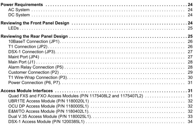
ONTENTSPower Requirements . . . 24
AC System . . . 24 DC System . . . 24
Reviewing the Front Panel Design . . . 24
LEDs . . . 25
Reviewing the Rear Panel Design . . . 25
10BaseT Connection (JP1) . . . 26 T1 Connection (JP2) . . . 26 DSX-1 Connection (JP3). . . 27 Maint Port (JP4) . . . 27 Main Port (J1) . . . 28 Alarm Relay Connection (P5) . . . 28 Customer Connection (P2) . . . 29 T1 Wire-Wrap Connection (P3). . . 30 Power Connection (P6, P7). . . 31
Access Module Interfaces . . . 31
Quad FXS and FXO Access Modules (P/N 1175408L2 and 1175407L2) . . . 31 UBR1TE Access Module (P/N 1180020L1) . . . 32 OCU DP Access Module (P/N 1180005L1) . . . 32 E&M/TO Access Module (P/N 1180402L1). . . 32 Dual V.35 Access Module (P/N 1180025L1). . . 33 DSX-1 Access Module (P/N 1200385L1) . . . 34
F
IGURESFigure 1. Total Access 600 Series Front Panel Layout . . . 24 Figure 2. Total Access 850 Rear Panel. . . 25 Figure 3. Connector Pinout . . . 30 Figure 4. Alternate Power Connection . . . 31 Figure 5. Connector Pin Assignments. . . 31
T
ABLESTable 1. Total Access 850 Backplane Connections . . . 25 Table 2. Ethernet Pinout . . . 26 Table 3. Network Connection Pinout . . . 26 Table 4. DSX-1 Network Connection Pinout . . . 27 Table 6. V.35 Winchester Pinout . . . 28 Table 5. Maint Pinout . . . 28 Table 7. Alarm Relay Connector Pinout . . . 29 Table 8. Alarm Notification . . . 29 Table 9. T1 Wire-Wrap Connector Pinout . . . 30
Table 10. UBR1TE Pinout . . . 32 Table 11. OCU DP Pinout . . . 32 Table 12. E&M/TO Pinout . . . 33 Table 13. Dual V.35 Pinout . . . 33 Table 14. DSX-1 Pinout . . . 34
1.
EQUIPMENT DIMENSIONS
The Total Access 600 Series base unit is 8.5” W, 11” D, and 3.5” H and can be mounted in a 19-inch or 23-inch rack (mounting brackets included in shipment). All other equipment (modules) fit inside the base unit.
2.
POWER REQUIREMENTS
Regardless of the configuration of access modules installed in the base unit, the following power requirements apply:
AC System
90/130 VAC, 60 Hz, 50 Watt Max
DC System
40/56 VDC, 50 Watt Max
3.
REVIEWING THE FRONT PANEL DESIGN
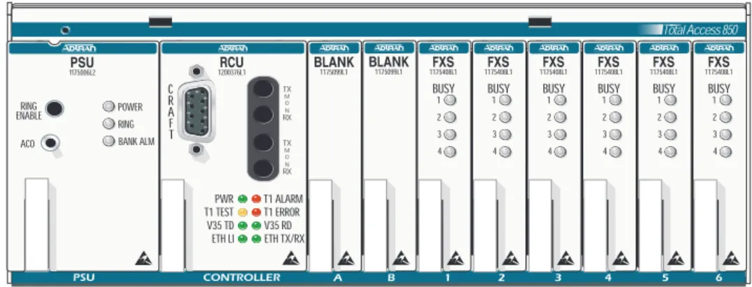
Figure 1 shows the Total Access 600 Series front panel. Refer to Access Module Interfaces on page 31 for a discussion of available modules and the front panel functions of each.
Figure 1. Total Access 600 Series Front Panel Layout
UL 60950/NEBS requires all Total Access 600 Seriesempty slots to be covered with blank
panels (P/N 1175099L1). Total Access 850 1175099L1 BLANK 1175099L1 BLANK BUSY 1 2 3 4 1175408L1FXS BUSY 1 2 3 4 1175408L1FXS BUSY 1 2 3 4 1175408L1FXS BUSY 1 2 3 4 1175408L1FXS BUSY 1 2 3 4 1175408L1FXS BUSY 1 2 3 4 1175408L1FXS 1200376L1RCU PWR T1 TEST V35 TD ETH LI TX M O N RX C R A F T TX M O N RX T1 ALARM T1 ERROR V35 RD ETH TX/RX ACO RING ENABLE 1175006L2PSU POWER RING BANK ALM
LEDs
• PWR The RCU has power
• T1 ALARM There is an alarm on the network T1 (yellow, red, or blue alarm) • T1 TEST The network T1 is in a test mode (loopback)
• T1 ERROR There are errors on the network T1 (framing errors, bipolar violations, or CRC errors) • V35 TD There is transmit data detected on the V.35 port
• V35 RD There is receive data detected on the V.35 port • ETH LI Ethernet link integrity
• ETH TX/RX There is transmit or receive data on the 10BaseT Ethernet port
4.
REVIEWING THE REAR PANEL DESIGN
Figure 2 shows the Total Access 850 backplane and Table 1 gives the backplane connections.
Figure 2. Total Access 850 Rear Panel
Table 1. Total Access 850 Backplane Connections
Ref Des Device/Label Technology
P1 wire-wrap strip clock/tests
P2 50 pin amphenol FXO, FXS, etc.
P3 wire-wrap strip alternate T1 interface
P5 wire-wrap strip alarms
P6 4 pin jack primary -48 V in
P7 3-lug terminal alternate -48 V in
JP1 RJ-48/E-NET 10BaseT Ethernet
JP2 RJ-48/T1 primary T1 interface
P7
P6
10BaseT Connection (JP1)
The 10BaseT port (RJ-48C) provides a 10BaseT Ethernet LAN connection, which is used for IP Routing,
TFTP, SNMP, and Telnet connections. The network connection follows, and Table 2 shows the pinout.
T1 Connection (JP2)
The MATRIX™System provides a single T1 port (located on the rear panel) and complies with the applicable ANSI and AT&T™ standards. The T1 interface provides the following functions:
• AMI or B8ZS
• Manual line build-out • D4 or ESF framing
• Network performance monitoring and reporting • Test loopbacks with QRSS generation checking • Extensive self-testing
The network connections follow, with the pinout shown in Table 3 below.
Table 3. Network Connection Pinout
JP3 RJ-48/FT1 DSX1 interface
JP4 RJ-48/MAINT RS 232 craft interface
J1 V.35 Nx56K/64K
CONNECTOR TYPE (USOC) RJ-48C
PART NUMBER AMP# 555164-2
Table 2. Ethernet Pinout
Pin Name Description
1 TX1 Transmit Positive 2 TX2 Transmit Negative 3 RX1 Receive Positive 4, 5 UNUSED — 6 RX2 Receive Negative 7, 8 UNUSED —
CONNECTOR TYPE (USOC) RJ-48C
Pin Name Description
1 RXDATA-RING Receive data from the network 2 RXDATA-TIP Receive data from the network
3 UNUSED —
DSX-1 Connection (JP3)
The MATRIX™System provides a single DSX-1 port (located in the rear of the unit) and complies with the applicable ANSI and AT&T™standards. The DSX-1 interface provides the following functions: • AMI or B8ZS
• Manual line build-out • D4 or ESF framing
The network connections follow, with the pinout shown in Table 4.
Table 4. DSX-1 Network Connection Pinout
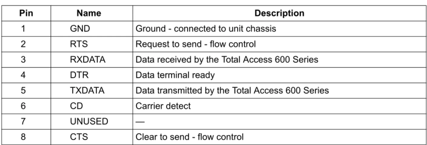
Maint Port (JP4)
The Maint port (EIA-232) connects to a computer or modem. The control port input provides the following functions:
• Accepts EIA-232 input from a PC or a modem for controlling the Total Access 600 Series. • Operates at 2400, 9600, 19200, or 38400 bps.
• Acts as input for either VT 100 or PC control.
• Acts as an interface for flash memory software downloads using XMODEM. The Maint connection follows, and Table 5 shows the pinout.
5 TXDATA-TIP Transmit data toward the network
6, 7, 8 UNUSED —
CONNECTOR TYPE (USOC) RJ-48C
Pin Name Description
1 R TXDATA-RING Transmit data from the network 2 T TXDATA-TIP Transmit data from the network
3 — UNUSED —
4 R1 RXDATA-RING Receive data toward the network 5 T1 RXDATA-TIP Receive data toward the network
6, 7, 8 — UNUSED —
CONNECTOR TYPE RJ-48C
PART NUMBER AMP# 555164-2
Main Port (J1)
Each port of the Dual Nx56/64 Option Module has a V.35 Winchester-style connection as defined in the table below.
Table 6. V.35 Winchester Pinout
Alarm Relay Connection (P5)
This connection alerts the user when a selected alarm condition exists. Alarm relay contacts are open during normal operation. The alarm relay contacts close in the event of a local alarm condition or the receipt of an alarm from the T1 carrier. In a carrier alarm condition such as a Red, Yellow, or Blue
(unframed all 1s), various alarm contacts in the PSU close. Carrier alarm conditions cause the Total Access 850 to initiate trunk processing. The following chain of events then occur:
1. MJ will be directly shorted to MJR. 2. MJV will be directly shorted to MJVR.
Contacts MJ and MJR can be overridden manually during an alarm condition by pressing the ACO pushbutton on the PSU faceplate. If the 3-Amp power fuse on the PSU trips, the -48ALM relay will close, providing a -48 VDC signal on that pin. This alarm cannot be overridden by the ACO pushbutton. Refer to
Table 5. Maint Pinout
Pin Name Description
1 GND Ground - connected to unit chassis
2 RTS Request to send - flow control
3 RXDATA Data received by the Total Access 600 Series
4 DTR Data terminal ready
5 TXDATA Data transmitted by the Total Access 600 Series
6 CD Carrier detect
7 UNUSED —
8 CTS Clear to send - flow control
Pin/CCIT Description Pin/CCIT Description
A/101 Protective ground (PG) V/115 RX clock (RC-A) to DTE
B/102 Signal ground (SG) X/115 RX clock (RC-B) to DTE
C/105 Request to send (RTS) from DTE P/103 Transmitted data (TD-A) from DTE D/106 Clear to send (CTS) to DTE S/103 Transmitted data (TD-B) to DTE E/107 Data set ready (DSR) to DTE Y/114 TX clock (TC-A) to DTE
E/109 Data carrier detect AA/114 TX clock (TC-B) to DTE
H/— Data terminal ready (DTR) from DTE U/113 External TX clock (ETC-A) from DTE
J/— Ring indicator (RI) W/113 External TX clock (ETC-B) from DTE
R/104 Received data (RD-A) to DTE NN/— Test mode (TM) to DTE T/104 Received data (RD-B) to DTE
Table 8 on page 29 for alarm notifications.
Table 7 shows the pinout for the Alarm Relay connector.
Table 8. Alarm Notification
Customer Connection (P2)
One 50-pin female amphenol connector (P2) provides the interconnect wiring for the access modules located in slots 1 through 6 of the chassis. This connector is usually terminated with a punch-down block for premises wiring or connected directly to a cross-connect or main distribution frame. Figure 3 details the connector pinout.
Table 7. Alarm Relay Connector Pinout
Pin Name Description
1 -48 ALM DC alarm output.
2 MJVR Closes when a selected alarm condition is present.
3 MJV Common connection between external circuitry and NC or NO terminal.
4 MJR Major alarm audible common
5 MJ Major alarm audible
Alarm Condition Relays Activated MJR MJVR -48 ALM
Red Alarm X X
Yellow Alarm X X
AIS Alarm X X
PSU Power Fuse Fails X X X
Alarms ACO Deactivates X X
Figure 3. Connector Pinout
T1 Wire-Wrap Connection (P3)
There are two termination points for connecting the network T1 to the chassis: the primary RJ-48 connector (JP2) and the alternate wire-wrap pins on terminal strip P3 (see Figure 2). Only one connector type is used (not both). The T1 primary connection is via the RJ-48 connector labeled T1 (JP2). This arrangement provides a convenient T1 connection for those installations where a T1 Smart Jack is used. Table 9 shows the pinout for the T1 wire-wrap connector.
Table 9. T1 Wire-Wrap Connector Pinout P3 Wire-Wrap Connections
Pin Name Description
1 R1 DS1 Ring input from network 2 T1 DS1 Tip input from network 3 R DS1 Ring output from network 4 T DS1 Tip output from network
5 Gnd Ground 26 1 27 2 28 3 29 4 30 5 31 6 32 7 33 8 34 9 35 10 36 11 37 12 38 13 39 14 40 15 41 16 42 17 43 18 44 19 45 20 46 21 47 22 48 23 49 24 50 25 R T R T R T R T R T R T R T R T R T R T R T R T R T R T R T R T R T R T R T R T NC NC P P P P P P P P P P P P P P P P P P P P 50 PIN AMP RECEPTACLE Slot 1 Slot 2 Slot 3 Slot 4 Slot 5 T T R T T R R Slot 6 P P P P Circuit 1 Circuit 2 Circuit 3 Circuit 4 Circuit 1 Circuit 2 Circuit 3 Circuit 4 Circuit 1 Circuit 2 Circuit 3 Circuit 4 Circuit 1 Circuit 2 Circuit 3 Circuit 4 Circuit 1 Circuit 2 Circuit 3 Circuit 4 Circuit 1 Circuit 2 Circuit 3 Circuit 4 R
Power Connection (P6, P7)
There are two power connections on the backplane: a modular DC plug (P6), and a three lug terminal strip (P7) (refer to Figure 2). The primary connection is the modular plug, which receives -48 VDC from the ADTRAN power supply/battery charging unit (P/N 1175043L2). The alternate connection is screw terminal P7, which can be used if -48 VDC is available as in central office applications. The screw terminal connection is shown in Figure 4.
Figure 4. Alternate Power Connection
5.
ACCESS MODULE INTERFACES
Quad FXS and FXO Access Modules (P/N 1175408L2 and 1175407L2)
The Quad FXS and FXO Access Modules use the 50-pin female amphenol connector on the rear of the Total Access 850 chassis to provide the interconnect wiring for the four analog circuits on each access module. Figure 5 shows the pinout connection for the amphenol connector. See Figure 3 on page 30 for closer detail.
Figure 5. Connector Pin Assignments
During installation, power should be the last connection made after all other wire-wrap connections are completed.
20 AWG RING LUG 20 AWG SOLID 16 AWG STRANDED TO FUSE PANEL TO WIRE WRAP FRAME GROUND 16 AWG RING LUG BLK FG BLK GRD RED -48V 26 1 27 2 28 3 29 4 30 5 31 6 32 7 33 8 34 9 35 10 36 11 37 12 38 13 39 14 40 15 41 16 42 17 43 18 44 19 45 20 46 21 47 22 48 23 49 24 50 25 R T R T R T R T R T R T R T R T R T R T R T R T R T R T R T R T R T R T R T R T NC P P P P P P P P P P P P P P P P P P P P 50 PIN AMP RECEPTACLE Slot 1 Slot 2 Slot 3 Slot 4 Slot 5 T T R T T R R Slot 6 P P P P Circuit 1 Circuit 2 Circuit 3 Circuit 4 Circuit 1 Circuit 2 Circuit 3 Circuit 4 Circuit 1 Circuit 2 Circuit 3 Circuit 4 Circuit 1 Circuit 2 Circuit 3 Circuit 4 Circuit 1 Circuit 2 Circuit 3 Circuit 4 Circuit 1 Circuit 2 Circuit 3 Circuit 4 R
UBR1TE Access Module (P/N 1180020L1)
Each port of the UBR1TE Access Module provides an ISDN U-interface and allows the transport of Basic Rate 2B+D information over the T1 carrier and twisted pair wiring. Table 10 gives the pinout for this jack.
OCU DP Access Module (P/N 1180005L1)
The OCU DP module is a single port access module used to provide the interface between a DS0 time slot on the T1 and a 4-wire DDS device at the customer premises. The OCU DP supports up to 18 kft of copper for remote DSU connectivity. This module is currently only supported by BCU L1 and L2. Table 11 gives this pinout.
E&M/TO Access Module (P/N 1180402L1)
The E&M/TO module is a single port Ear and Mouth/Transmit Only access module. The primary
application for this module is to provide PBX foreign exchange at the customer premises or tandem central office applications. This module is intended for interface with intra-building wiring. The E&M/TO module supports both 2 and 4 wire operation. This module is currently only supported by BCU L1 and L2.
CONNECTOR TYPE (USOC) RJ-45
Table 10. UBR1TE Pinout Total Access 850 Slot Port 1 T/R 1 26/1 2 30/5 3 34/9 4 38/13 5 42/17 6 46/21
Table 11. OCU DP Pinout Total Access 850 Slot T/R RX T1/R1 TX 1 26/1 27/2 2 30/5 31/6 3 34/9 35/10 4 38/13 39/14 5 42/17 43/18 6 46/21 47/22
Table 12 gives the E&M/TO module pinout.
Dual V.35 Access Module (P/N 1180025L1)
The Dual V.35 module is designed to provide additional V.35 interfaces for customer premises equipment. The module takes up two access slots; therefore three modules (six additional ports) can be added to an empty chassis. The Total Access 850 can support a maximum of seven V.35 interfaces. V.35 ports provided by the Dual V.35 module are accessed on the front of the Total Access 850. This module is currently only supported by the TDM version of the T1 RCU. An ADTRAN 35 ft DB-26/V.35 adapter cable is required (P/N 1200167L1). The pinout for the V.35 end of this cable is shown in Table 13.
Table 12. E&M/TO Pinout
Slot 1 Slot 2 Slot 3 Slot 4 Slot 5 Slot 6
Pin 1 5 9 13 17 21 RING 2 6 10 14 18 22 RING 1 3 7 11 15 19 23 SG LEAD 4 8 12 16 20 24 SB LEAD Pin 26 30 34 38 42 46 TIP 27 31 35 39 43 47 TIP 1 28 32 36 40 44 48 E LEAD 29 33 37 41 45 49 M LEAD
Table 13. Dual V.35 Pinout
Pin Description
A Frame ground
B Signal ground
C Request to send (RTS) D Clear to send (CTS) E Data set ready (DSR)
F Received line signal detector (DCD) H Data terminal ready (DTR)
J Ring indicator (RI)
K unused
L Local loopback (LL)
M unused
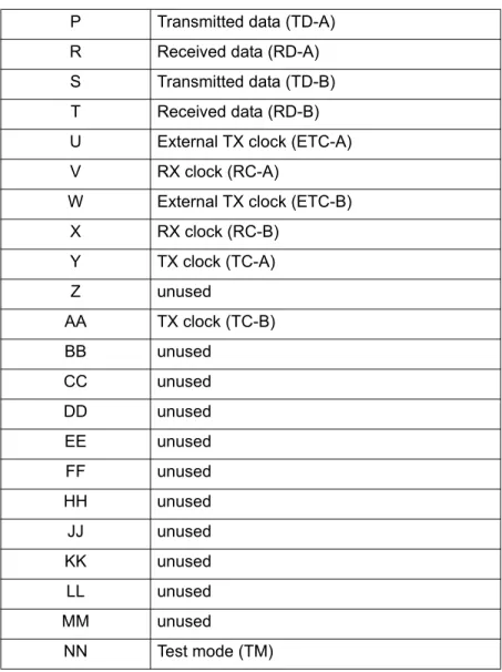
DSX-1 Access Module (P/N 1200385L1)
The DSX-1 Module is a single port (RJ-45) access module that provides a DSX-1 connection for customer premises equipment. This module supports PBXs or other equipment with a DSX-1/FT1 interface. This module is currently supported by the T1 RCU only.
Table 14. DSX-1 Pinout
P Transmitted data (TD-A) R Received data (RD-A) S Transmitted data (TD-B) T Received data (RD-B) U External TX clock (ETC-A)
V RX clock (RC-A)
W External TX clock (ETC-B)
X RX clock (RC-B) Y TX clock (TC-A) Z unused AA TX clock (TC-B) BB unused CC unused DD unused EE unused FF unused HH unused JJ unused KK unused LL unused MM unused NN Test mode (TM)
Pin Name Description
1 R1 | RXDATA-RING Receive data from the network (RING) 2 T1 | RXDATA-TIP Receive data from the network (TIP)
3 UNUSED —
4 R | TXDATA-RING Transmit data towards the network (RING) 5 T | TXDATA-TIP Transmit data towards the network (TIP)
6,7,8 UNUSED —
C
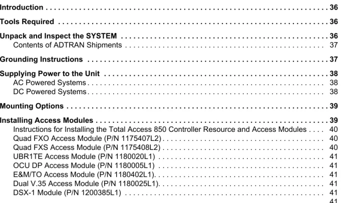
ONTENTSIntroduction . . . 36 Tools Required . . . 36 Unpack and Inspect the SYSTEM . . . . 36
Contents of ADTRAN Shipments . . . 37
Grounding Instructions . . . 37 Supplying Power to the Unit . . . 38
AC Powered Systems . . . 38 DC Powered Systems . . . 38
Mounting Options . . . 39 Installing Access Modules . . . 39
Instructions for Installing the Total Access 850 Controller Resource and Access Modules . . . . 40 Quad FXO Access Module (P/N 1175407L2) . . . 40 Quad FXS Access Module (P/N 1175408L2) . . . 40 UBR1TE Access Module (P/N 1180020L1) . . . 41 OCU DP Access Module (P/N 1180005L1) . . . 41 E&M/TO Access Module (P/N 1180402L1). . . 41 Dual V.35 Access Module (P/N 1180025L1). . . 41 DSX-1 Module (P/N 1200385L1) . . . 41 . . . 41
F
IGURES1.
INTRODUCTION
This section discusses the installation process of the Total Access 850 installation.
2.
TOOLS REQUIRED
The tools required for wallmount installation of the Total Access 850 shelf are: • Four #8 x 3/4 inch pan-head wood screws
• Drill and drill bit set
• Flat head screwdriver (medium)
• Two Phillips head screwdrivers (small /medium) • Wire-wrap gun (optional)
• 5-pair male amphenol cable (customer connection) • Selected punch-down block and tool
3.
UNPACK AND INSPECT THE SYSTEM
Each Total Access 850 is shipped in its own cardboard shipping carton. Open each carton carefully and avoid deep penetration into the carton with sharp objects.
After unpacking the unit, inspect it for possible shipping damage. If the equipment has been damaged in transit, immediately file a claim with the carrier, then contact ADTRAN Customer Service (see Customer
Service, Product Support Information, and Training in the front of this manual).
To prevent electrical shock, do not install equipment in a wet location or during a lightning storm.
During installation, power should be the last connection made.
Electronic modules can be damaged by static electrical discharge. Before handling modules, wear an antistatic discharge wrist strap to prevent damage to electronic components. Place modules in antistatic packing material when transporting or storing. When working on modules, always place them on an approved antistatic mat that is electrically grounded.
Contents of ADTRAN Shipments
Your ADTRAN shipment of the Total Access 850 chassis includes the following items: • The Total Access 850 Base Unit
• The Total Access 850Family System CD • Wallmount brackets and screws
• RJ-45 to RJ-45 8-pin cable (15 ft) - ADTRAN P/N 3125M008 • UL 1950 Notice Card - ADTRAN P/N 61200375L1-17
• Manual Ordering Information Notice Card - ADTRAN P/N 61200375L1-1702
4.
GROUNDING INSTRUCTIONS
To following provides grounding instruction information from the Underwriters’ Laboratory UL1950 Standard for Safety of Information Technology Equipment Including Electrical Business Equipment, of July 28, 1995.
An equipment grounding conductor that is not smaller in size than the ungrounded branch-circuit supply conductors is to be installed as part of the circuit that supplies the product or system. Bare, covered, or insulated grounding conductors are acceptable. Individually covered or insulated equipment grounding conductors shall have a continuous outer finish that is either green, or green with one or more yellow stripes. The equipment grounding conductor is to be connected to ground at the service equipment. The attachment-plug receptacles in the vicinity of the product or system are all to be of a grounding type, and the equipment grounding conductors serving these receptacles are to be connected to earth ground at the service equipment.
A supplementary equipment grounding conductor shall be installed between the product or system and ground that is in addition to the equipment grounding conductor in the power supply cord.
The supplementary equipment grounding conductor shall not be smaller in size than the ungrounded branch-circuit supply conductors. The supplementary equipment grounding conductor shall be connected to the product at the terminal provided, and shall be connected to ground in a manner that will retain the ground connection when the product is unplugged from the receptacle. The connection to ground of the supplementary equipment grounding conductor shall be in compliance with the rules for terminating bonding jumpers at Part K or Article 250 of the National Electrical Code, ANSI/NFPA 70. Termination of the supplementary equipment grounding conductor is permitted to be made to building steel, to a metal electrical raceway system, or to any grounded item that is permanently and reliably connected to the electrical service equipment ground.
The supplemental grounding conductor shall be connected to the equipment using a number 8 ring terminal and should be fastened to the grounding lug provided on the rear panel of the equipment. The ring terminal should be installed using the appropriate crimping tool (AMP P/N 59250 T-EAD Crimping Tool or equivalent.)
5.
SUPPLYING POWER TO THE UNIT
AC Powered Systems
The AC powered Total Access 850 (requires the use of the AC Power supply unit P/N 1175043L2) comes equipped with a 6-foot power cord with a 3-prong plug for connecting to a grounded power receptacle. As shipped, the Total Access 850 is set to factory default conditions. After installing the chassis and any access modules, the Total Access 850 is ready for power-up. To power-up the unit, ensure that the unit is properly connected to an appropriate power source.
DC Powered Systems
The DC powered Total Access 850 comes equipped with a DC Power supply to furnish the voltages necessary for proper backplane operation. As shipped, the Total Access 850 is set to factory default conditions. After installing the chassis and any access modules, the Total Access 850 is ready for power-up.
• This unit shall be installed in accordance with Article 400 and 364.8 of the NEC NFPA
70 when installed outside of a Restricted Access Location (i.e., central office, behind a locked door, service personnel only area).
• Power to the Total Access 850 AC system must be from a grounded 90-130 VAC, 50/60
Hz source.
• The power receptacle uses double-pole, neutral fusing.
• Maximum recommended ambient operating temperature is 45 ºC.
• This unit shall be installed in accordance with Article 400 and 364.8 of the NEC NFPA
70 when installed outside of a Restricted Access Location (i.e., central office, behind a locked door, service personnel only area).
• Power to the Total Access 850 DC system must be from a reliably grounded -48 VDC
source which is electrically isolated from the AC source.
• The branch circuit overcurrent protection shall be a fuse or circuit breaker rated
minimum 48 VDC, maximum 20A.
6.
MOUNTING OPTIONS
The Total Access 850 chassis may be wallmounted or installed in a 19-inch or 23-inch rack. Wallmount brackets are included with the chassis. For a rackmount installation, the Total Access 850 Base Unit allows flush-face mount, face-forward mount, center mount, and rear mount.
7.
INSTALLING ACCESS MODULES
Figure 1 shows the slot numbering designation as viewed from the front of the Total Access 850 chassis. The functionally identical option slots only accept Total Access™ access modules and the controller slots only accept Total Access 850 controller modules.
Figure 1. Total Access 850 Slot Designation (Front View)
The Total Access 850 chassis includes wall mount brackets. If rack mount brackets are needed, use part number 1175045L1 or 1175046L1 for 19 inch or 23 inch, respectively.
Be careful not to upset the stability of the equipment mounting rack when installing this product.
Access modules are intended to be serviced by qualified service personnel only. Total Access 850 1175099L1 BLANK 1175099L1 BLANK BUSY 1 2 3 4 1175408L1FXS BUSY 1 2 3 4 1175408L1FXS BUSY 1 2 3 4 1175408L1FXS BUSY 1 2 3 4 1175408L1FXS BUSY 1 2 3 4 1175408L1FXS BUSY 1 2 3 4 1175408L1FXS 1200376L1RCU PWR T1 TEST V35 TD ETH LI TX M O N RX C R A F T TX M O N RX T1 ALARM T1 ERROR V35 RD ETH TX/RX ACO RING ENABLE 1175006L2PSU POWER RING BANK ALM
RCU ACCESS MODULES
Instructions for Installing the Total Access 850 Controller Resource and Access
Modules
Individual access modules insert from the front. A locking bar holds the modules in place for added security. Disengaging the captured screw allows removal of the locking bar. To install Controller Resource and Access Modules for the Total Access 850, follow the steps outlined below.
1. Hold the access module by the faceplate while supporting the bottom side. 2. Align the module edges to the guide grooves for the designated slot. 3. Insert the module until the edge connector seats firmly into the backplane. 4. Lock the module in place by pushing in on the locking lever.
5. Connect the cables to the associated device(s). All wiring connections terminate on the backplane of the chassis.
Quad FXO Access Module (P/N 1175407L2)
Shipping Contents
The ADTRAN shipment of the Quad FXO Access Module includes the following items: • Quad FXO Access Module
• Quad FXO Access Module Job Aid • Quad FXS/FXO Compliance Sheet
Quad FXS Access Module (P/N 1175408L2)
Shipping Contents
The ADTRAN shipment of the Quad FXS Access Module includes the following items: • Quad FXS Access Module
• Quad FXS Access Module Job Aid • Quad FXS/FXO Compliance Sheet
Disable ring voltage before exposing the backplane or accessing channel units. For the L2 PSU, press the Ring Enable button. For older L1 PSUs, remove the 20 Hz fuse.
UBR1TE Access Module (P/N 1180020L1)
Shipping Contents
The ADTRAN shipment of the UBR1TE Access Module includes the following items: • UBR1TE Access Module
• UBR1TE Access Module Job Aid
OCU DP Access Module (P/N 1180005L1)
Shipping Contents
The ADTRAN shipment of the OCU DP Access Module includes the following items: • OCU DP Access Module
• OCU DP Access Module Job Aid
E&M/TO Access Module (P/N 1180402L1)
Shipping Contents
The ADTRAN shipment of the E&M/TO Access Module includes the following items: • E&M/TO Access Module
• E&M/TO Access Module Job Aid
Dual V.35 Access Module (P/N 1180025L1)
Shipping Contents
The ADTRAN shipment of the Dual V.35 Access Module includes the following items: • Dual V.35 Access Module
• Dual V.35 Access Module Job Aid
DSX-1 Module (P/N 1200385L1)
The ADTRAN shipment of the DSX-1 Module includes the following items: • DSX-1 Module
This section of the Total Access 850 System Manual is designed for use by network administrators and others who will configure and provision the system. It contains information about navigating the VT100 user interface, configuration information, and menu descriptions.
C
ONTENTSNavigating the Terminal Menu . . . 42
Terminal Menu Window . . . 42 Menu Path . . . 42 Window Panes . . . 43 Additional Terminal Menu Window Features . . . 44 Navigating using the Keyboard Keys . . . 45 Moving through the Menus . . . 45 Session Management Keystrokes . . . 46 Configuration Keystrokes . . . 46 Getting Help . . . 47
Terminal Menu and System Control . . . 47
Selecting the Appropriate Menu . . . 47 Security Levels . . . 48
Access Module Menu Descriptions . . . 49 Channel Bank Menus . . . 49 Quad FXO Module Menus . . . 50 UBR1TE Module Menus . . . 52 Quad FXS Module Menus . . . 55
F
IGURESFigure 1. Top-Level Terminal Menu Window. . . 42 Figure 2. Alternate Menu View . . . 43 Figure 3. Channel Bank > Modules Menu . . . 49 Figure 4. Network Locations . . . 53
1.
NAVIGATING THE TERMINAL MENU
Terminal Menu Window
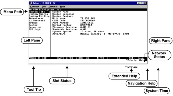
The Total Access 850 uses a multi-level menu structure that contains both menu items and data fields. All menu items and data fields display in the terminal menu window (see Figure 1), through which you have complete control of the Total Access 850.
Figure 1. Top-Level Terminal Menu Window
Menu Path
The first line of the terminal menu window (the menu path) shows the session’s current position (path) in the menu structure. For example, Figure 1 shows the top-level menu with the cursor on the SYSTEM INFO submenu; therefore, the menu path reads TA 850 RCU > System Info.
Left Pane Menu Path
Right Pane
Tool Tip System Time
Navigation Help Extended Help Slot Status ^A=more Status Network
Window Panes
When you first start a terminal menu session, the terminal menu window is divided into left and right panes. The left pane shows the list of available submenus, while the right pane shows the contents of the currently selected submenu.
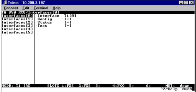
You can view the terminal windows in two ways: with fields and submenus displaying horizontally across the right pane, or with fields and submenus displaying vertically down the right pane. Viewing submenus vertically rather than horizontally allows you to see information at a glance rather than scrolling
horizontally across the window. To change the view, move your cursor to an index number and press
<Enter>. Figure 2 shows this alternate view. Fields and submenu names may vary slightly in this view.
Window Pane Navigation
Use the following chart to assist you in moving between and within the two window panes.
Right Window Pane Notation
The right window pane shows the contents of the currently selected menu. These contents can include both submenu items and data fields. Some submenus contain additional submenus and some data fields contain additional data fields. The following chart explains the notation used to identify these
additional items.
Additional Terminal Menu Window Features
• Tool Tip - provides a brief description of the currently selected mode • Network Status - displays network status information, Up or Down
• Slot Status - displays type of module installed in each slot. No entry will appear for slots not containing a module.
• Extended Help - displays information about selected commands (CTRL+A)
• Navigation Help - lists characters used for navigating the terminal menu and session management (CTRL+Z)
• System Time - displays current time
To do this... Press this key...
Move from left pane to right pane Tab Enter Right arrow Move from right pane to left pane Tab
Escape Left arrow Backspace Move within each pane Up arrow
Down arrow Left arrow Right arrow
This notation... Means that...
[+] More items are available when selected
<+> An action is to be taken, such as activating a test Highlighted menu item You can enter data in this field
Navigating using the Keyboard Keys
You can use various keystrokes to move through the terminal menu, to manage a terminal menu session, and to configure the system. Press <CTRL+Z> to activate a pop-up screen listing the navigation
keystrokes.
Moving through the Menus
To do this... Press this key...
Return to the home screen H
Jump between two menu items
Press <J> while the cursor is located on a menu item, and you jump back to the main screen.
Go to another menu item, press <J>, and you jump back to the screen that was displayed the first time you pressed <J>.
Press <J> anytime you want to jump between these items.
J
Select items Arrows
Edit a selected menu item Enter
Cancel an edit Escape
Close pop-up help screen Escape
Move between the left and right panes Tab
Arrows
Move to the top of a screen A
Move to the bottom of a screen Z
Ascend one menu level Backspace
Jump to terminal mode (only supported in T1 TDM code) Ctrl + T Jump to NAT menu (only supported in T1 TDM code) Ctrl + N
Session Management Keystrokes
Configuration Keystrokes
To do this... Press this key...
Log out of a session CTRL+L
Refresh the screen
To save time, only the portion of the screen that has changed is refreshed. This option should only be necessary if the display picks up incorrect characters.
CTRL+R
To do this... Press this key...
Restore factory default settings.
This setting restores the factory defaults based on the location of the cursor. If the cursor is on a module line (in the MODULES menu), then only the selected module is updated to factory defaults.
F
Copy selected items to the clipboard.
The amount of information you can copy depends on the cursor location when you press <C>:
If the cursor is over an editable field, only that item is copied.
If the cursor is over the index number of a list, then all of the items in the row of the list are copied. For example, if the cursor is over the SLOT # field in the MODULES screen, all of the information associated with the slot is copied.
C
Paste the item stored in the clipboard, if the information is compatible. You must confirm all pastes - except those to a single editable field.
P
Increment the value of certain types of fields by one when you paste information into those fields.
> Decrement the value of certain types of fields by one when you paste information into those fields.
Getting Help
The bottom line of the terminal menu window contains context-sensitive help information. When the cursor is positioned over a set of configuration items, a help message displays (when available) providing a description of the item. When more detailed help is available for a particular item, ^A displays at the bottom of the window. At this point, if you press <CTRL+A>, a pop-up help screen displays with information about the item.
Press <CTRL+Z> to activate a help screen that displays the available keystrokes you can use to navigate the terminal menu. Press <Esc> to cancel these pop-up windows.
2.
TERMINAL MENU AND SYSTEM CONTROL
Selecting the Appropriate Menu
The terminal menu is the access point to all other operations. Each terminal menu item has several functions and submenus that identify and provide access to specific operations and parameters. Use the chart below to help select the appropriate terminal menu.
Insert a new list item.
For example, add a new item to the TELNET USER LISTconnection list by pressing <I> while the cursor is over the index number.
I
Delete a list item.
For example, delete an item from the TELNET USER LISTconnection list by pressing
<D> while the index number is active.
D
To do this... Go to this menu...
Review and monitor general system information for the Total Access 850
SYSTEM INFO
Set up the operational configuration for the Total Access 850 SYSTEM CONFIG Upgrade firmware, do config transfers, ping, and access terminal mode SYSTEM UTILITY Define, configure, and monitor all Total Access 850 Router functions ROUTER
Review and configure settings for each installed module, configure the DS0 maps, and configure the V.35 parameters
CHANNEL BANK
Security Levels
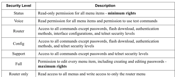
To edit terminal menu items, you must have a password and the appropriate security level. Table 1 describes the security levels.
Table 1. Password Security Level
Security Level Description
Status Read-only permission for all menu items - minimum rights
Voice Read permission for all menu items and permission to use test commands Router Access to all commands except passwords, flash download, authentication
methods, interface configurations, and telnet security levels
Config Access to all commands except passwords, flash download, authentication methods, and telnet security levels
Support Access to all commands except passwords and telnet security levels
Full Permission to edit every menu item, including creating and editing passwords - maximum rights Router only Read access to all menus and write access to only the router menu
3.
ACCESS MODULE MENU DESCRIPTIONS
This section describes the Total Access 850 FXO, UBR1TE, and FXS menu and submenu options. Refer to the other User Interface Guides in this manual for detailed information on other Total Access 850 menus and submenus.
C
HANNELB
ANKM
ENUSAccess the FXO, UBR1TE, and FXS menus through the CHANNEL BANKmenu, which provides access to the module configuration, DS0 maps, and V.35 setup.
C
HANNELB
ANK> M
ODULESUse the CHANNEL BANK > MODULESmenu to view and set the parameters shown in Figure 3 on page 51 for the FXO, UBR1TE, and FXS modules.
Figure 3. Channel Bank > Modules Menu
The following Access Module Menu Descriptions section only applies to Total Access 850 systems with firmware versions prior to the A.04 or C.04 code releases. Refer to the individual technology based User Interface Guides (T1 TDM and ATM) for a detailed discussion of the newer menu selections.
Q
UADFXO M
ODULEM
ENUSC
HANNELB
ANK> M
ODULES> M
ENUDisplays the configuration options for the selected module. To access the submenus for this item, use the arrow keys to scroll to the menu column for the module you want to edit and press enter.
C
HANNELB
ANK> M
ODULES> T
YPEDisplays the type of module installed in the slot. The Total Access 850 automatically detects the type of module installed in each slot, and the TYPE field displays the module name. This is a read-only field.
C
HANNELB
ANK> M
ODULES> M
ENU> M
ODEChoices are LOOP START, GROUND START, and DPT. Default is LOOP START.
C
HANNELB
ANK> M
ODULES> M
ENU> TX (dB)
Sets the TX direction level points. The value entered must be less than 10 dB. Default is 0.0 dB.
C
HANNELB
ANK> M
ODULES> M
ENU> RX (dB)
Sets the RX direction level points. The value entered must be less than 10 dB. Default is 0.0 dB. The 0.0 dB setting is the strongest signal. The 10.0 dB sett