1
Evaluation of L-PRO 4000 for End-to-End
Communication
Using IEC 61850 Protocol With RFL IMUX 2000 Multiplexer
Introduction
The ERLPhase L-PRO 4000 Transmission Line Protection Relay provides standard communication-aided protection options such as Permissive Over-Reaching Transfer Trip (POTT), a combination of POTT with Weak Infeed (WI), Directional Comparison Blocking (DCB) and Permissive Under-Reaching Transfer Trip (PUTT). This document evaluates L-PRO 4000’s IEC 61850 GOOSE messaging capabilities, applicable to above communication-aided protection (Trip/Block) schemes. The RFL IMUX 2000 multiplexers with standard LAN bridge adapters (MA-427 units) were used as the interfacing device. Testing was carried out with all the other standard functionalities (protection, recording, etc.) enabled on the L-PRO 4000 relays.
Description
Figure 1 shows the test setup used to evaluate the performance of relays. In this testing, each relay was
connected to the corresponding IMUX 2000 multiplexer via the LAN bridge adapter. A direct cable was assumed between T1/E1 connections of IMUX units.
Figure 1: Test setup.
Evaluation of Time Delays
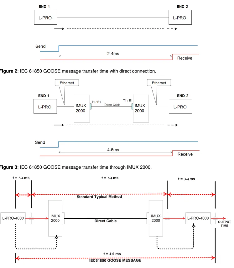
In order to investigate the additional time delays introduced due to the IMUX 2000 units, time delays involved in transferring GOOSE messages from one relay to the other were estimated with and without the use of IMUX 2000 units. Test cases were repeated several times and the average time delays associated with each case are shown in Figures 2 and 3. As it can be seen from these results, the IMUX units have introduced an additional time delay of approximately 2-4 ms in transferring GOOSE messages. Bandwidth of the serial communication used in this testing was 1536 Kbps.
As shown in Figure 4, time delay involved in the standard peer-to-peer communication through digital input and output contacts would be approximately 9-12 ms (including the time delays associated with input/output contact operating times).
2
Figure 2: IEC 61850 GOOSE message transfer time with direct connection.
Figure 3: IEC 61850 GOOSE message transfer time through IMUX 2000.
Figure 4: Comparison of communication time delays between standard method and IEC 61850 GOOSE messaging.
3
Effect of Communication Bandwidth
The RFL multiplexers are capable of handling variable communication bandwidths depending on availability. In order to evaluate the effect of the serial communication’s bandwidth, the above test was repeated for different bandwidth rates and results are summarized in Table 1. As it can be seen from the results, using a rate of 1024 Kbps or higher would ensure a transfer time of 4-6 ms.
Table 1: Effect of Bandwidth
Bandwidth (Kbps) Transfer time(ms)
64 21-23 128 13-15 256 7-9 512 6-8 1024 4-6 1536 4-6
Effect of Loading
In order to evaluate the effect of the loading in sending multiple GOOSE messages, two sets of relays located at two ends were set to communicate with each other simultaneously. In this case, the delay in sending GOOSE messages between each other was observed in the range of 10-12 ms (shown in Figure 5). The communication bandwidth used in this testing is 1536 Kbps.
4
Protection Application
For this application two L-PRO 4000 relays were used, applied at each end of the transmission line (shown in Figure 6).
Figure 6: End-to-end line protection scheme using L-PRO.
Each relay was set to operate in the POTT scheme. Please refer to the L-PRO 4000 User Manual [1] for more details about the POTT scheme and its settings. Permissive transfer signals between each relay were
exchanged using IEC 61850 GOOSE messaging facility available with the L-PRO 4000. More details about the use of IEC 61850 GOOSE messaging facility in L-PRO 4000 can be found in [2]. The communication bandwidth used in this testing is 1536 Kbps.
System Parameters and Settings
Figure 7 shows the parameters of the transmission system simulated in a Real-Time Digital Simulator (RTDS). The equivalent sources S1 and S2 were simulated with two different SIR values. The length of the transmission line was 250 kilometers.
5
Different types of faults (L-G, L-L and L-L-L) were simulated at different locations of the transmission system, as shown in Figure 8.
Figure 8: Fault locations.
The reach settings used for each relay are shown in Figure 9.
6
Results
Figure 10 shows the operation of L-PRO at Bus-A for an L-G fault simulated at 100% distance on the line. As shown in Figure 10, the relay was able to operate within 15 ms based on the information exchanged between relays.
Figure 10: Operation of L-PRO at Bus-A for 100% fault.
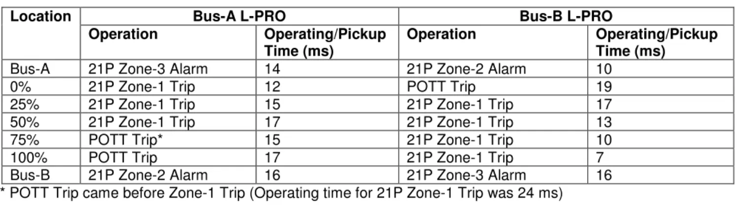
Tables 2-4 summarize the results obtained for all types of faults simulated at different distances. Results show the POTT scheme operated correctly during all test scenarios. Output contact time is considered to be
approximately 250µsec (by use of high speed outputs).
Table 2: Operation during L-G (single phase-to-ground) faults
Location Bus-A L-PRO Bus-B L-PRO
Operation Operating/Pickup
Time (ms)
Operation Operating/Pickup
Time (ms)
Bus-A 21N Zone-3 Alarm 13 21N Zone-2 Alarm 12
0% 21N Zone-1 Trip 10 POTT Trip 15
25% 21N Zone-1 Trip 13 21N Zone-1 Trip 14
50% 21N Zone-1 Trip 13 21N Zone-1 Trip 12
75% 21N Zone-1 Trip 17 21N Zone-1 Trip 9
100% POTT Trip 15 21N Zone-1 Trip 7
Bus-B 21N Zone-2 Alarm 13 21N Zone-3 Alarm 14
Zone-2 Alarm Dist. Sch. Send Dist. Sch. Received
7
Table 3: Operation during L-L (phase-to-phase) faults
Location Bus-A L-PRO Bus-B L-PRO
Operation Operating/Pickup
Time (ms)
Operation Operating/Pickup
Time (ms)
Bus-A 21P Zone-3 Alarm 14 21P Zone-2 Alarm 10
0% 21P Zone-1 Trip 12 POTT Trip 19
25% 21P Zone-1 Trip 15 21P Zone-1 Trip 17
50% 21P Zone-1 Trip 17 21P Zone-1 Trip 13
75% POTT Trip* 15 21P Zone-1 Trip 10
100% POTT Trip 17 21P Zone-1 Trip 7
Bus-B 21P Zone-2 Alarm 16 21P Zone-3 Alarm 16
* POTT Trip came before Zone-1 Trip (Operating time for 21P Zone-1 Trip was 24 ms)
Table 4: Operation during L-L-L (three-phase) faults
Location Bus-A L-PRO Bus-B L-PRO
Operation Operating/Pickup
Time (ms)
Operation Operating/Pickup
Time (ms)
Bus-A 21P Zone-3 Alarm 11 21P Zone-2 Alarm 8
0% 21P Zone-1 Trip 10 POTT Trip 15
25% 21P Zone-1 Trip 11 21P Zone-1 Trip 13
50% 21P Zone-1 Trip 13 21P Zone-1 Trip 10
75% POTT Trip* 15 21P Zone-1 Trip 12
100% POTT Trip 16 21P Zone-1 Trip 7
Bus-B 21P Zone-2 Alarm 12 21P Zone-3 Alarm 13
* POTT Trip came before Zone-1 Trip (Operating time for 21P Zone-1 Trip was 17 ms)
Conclusion
L-PRO 4000’s IEC 61850 GOOSE messaging performance was evaluated for station-to-station communication. The RFL IMUX 2000 multiplexers with MA-427 were used as interfacing devices to facilitate the communication between stations. An application example of the POTT protection scheme was also presented using a test transmission system simulated in a real time digital simulator (RTDS).
This study concludes:
• Using point-to-point serial connections between relays with RFL IMUX multiplexers operating at a 1536 Kbps bandwidth results in a 61850 GOOSE message taking an additional 2-4 ms transfer time.
• When the RFL IMUX 2000 multiplexers were loaded with traffic in addition to a relay to relay line protection application, the 61850 GOOSE messages between these relays was delayed by 4-6 ms. • Using the RFL IMUX 2000 multiplexers with the standard communication (just serial inputs and outputs
of the relays) results in near zero delay in communication transfer times. However, output contact operation and digital input hardware delays in the relays can add 6-8 ms (3-4 ms per relay) to the total time delay between relays, as shown in Figure 4.
References
[1] L-PRO 4000 User Manual, ERLPhase Power Technologies, Winnipeg, MB, Canada.
[2] IEC 61850 Interoperability Test Example Using ERLPhase Relays, ERLPhase Power Technologies, Winnipeg, MB, Canada.
[3] IMUX 2000 T1/E1 Multiplexer, User Manual, RFL Electronics Inc., NJ.
The specifications and product information contained in this document are subject to change without notice.