TABLE OF CONTENTS ABSTRACT . . . . . . . . 1 CHAPTER 1: INTRODUCTION . . . . . 2 1.1 Background of Project . . . 2 1.2 Problem Statement . . . . 2 1.3 Objectives . . . . . 3 1.4 Scope of Project . . . . 3
CHAPTER 2: LITERATURE REVIEW . . . . 3
2.1 TUAT/Karlsruhe Humanoid Hand . . 4
2.1.1 Introduction . . . . 4
2.1.2 Type of Grasping . . . 4
2.1.3 Mechanical Design for Fingers . 5
2.1.4 Results and Comparison . . 6
2.2 UB 3 Hand . . . 7
2.2.1 Introduction . . . . 7
2.2.2 Architecture and Kinematics of the Hand 7
CHAPTER 3: METHODOLOGY . . . . . 9
3.1 Identify the Problems . . . . 10
3.2 Literature Review . . . . 10 3.3 Conceptual Mechanism . . . 10 3.3.1 The Spring . . . . 12 3.3.1.1 Procedures . . . 12 3.3.1.2 Calculation . . . 13 3.4 Designing . . . . . 14 3.4.1 Conceptual Design . . . 14 3.4.2 Functional Design . . . 15 3.4.3 Production Design . . . 18 3.5 Simulation . . . . . 20 3.6 Fabrication . . . . . 22 3.6.1 Software . . . . 25 3.6.2 Circuit Board . . . . 27 3.6.2.1 Concept of H-bridge . . 27
3.6.2.2 Components of circuit board . 28
3.7 Testing . . . . . 32
3.7.1 Mechanism of humanoid finger . 33
3.7.2 Controlling the motor . . . 34
3.8 Analysis and Discussion. . . . 35
3.9 Documentation. . . . . 36
CHAPTER 5: CONCLUSION and RECOMMENDATIONS . 38
REFERENCES . . . . . . . 39
APPENDICES . . . . . . . 40
LIST OF FIGURES
Figure 1 The TUAT/Karlsruhe humanoid hand and human hand . 3
Figure 2 Typical Human Grasping . . . . . 5
Figure 3 Structure of human hand and the humanoid hand . . 5 Figure 4 Mechanical works on four fingers . . . . 6
Figure 5 Grasping examination by TUAT/Karlsruhe humanoid hand . 6 Figure 6 The UB Hand 3 and the human hand . . . . 7
Figure 7 Structure of the finger module of the UB Hand 3 . . 8 Figure 8 Complaint elements are made with close-wound helical springs 8 Figure 9 Grasping a bottle . . . . . . 8
Figure 10 Manipulation of a pen . . . . . . 8
Figure 11 The initial condition of finger (Straight) . . . 11
Figure 12 Bending finger (When the cable pulls) . . . . 11
Figure 13 Slowly straighten back (When the cable is loosened) . . 11 Figure 14 Newton-meter and spring . . . . . 12
Figure 15 The spring is tied down to Newton-meter . . . 12
Figure 16 The table and the graph . . . . . . 13
Figure 17 The conceptual design of humanoid finger . . . 15
Figure 18 The sketch of one humanoid finger . . . . 16
Figure 19 Distal . . . . . . . . 17
Figure 20 Intermediate . . . . . . . 17
Figure 21 Proximal . . . . . . . . 17
Figure 22 The palm . . . . . . . 17
Figure 23 Assemble the segments into one finger . . . . 17
Figure 24 Modified Intermediate . . . . . . 21
Figure 25 Before modified finger and after modified finger . . 21 Figure 26 Conventional Milling . . . . . . 22
Figure 27 Conventional Lathe . . . . . . 22
Figure 28 Linear Hack Saw . . . . . . 23
Figure 30 Fabricate Intermediate . . . . . . 24
Figure 31 Fabricate Distal . . . . . . . 24
Figure 32 CNC Milling . . . . . . . 24
Figure 33 The hollow part of the palm is cut out . . . . 24
Figure 34 Wire EDM is cutting a metal block . . . . 25
Figure 35 Logo for SOLID WORKS 2006 . . . . 26
Figure 36 Structure of H-bridge (Highlighted in Red) . . . 27
Figure 37 Two Basic States of H-Bridge . . . . . 28
Figure 38 Symbol for pMOSFET . . . . . . 29
Figure 39 MOSFET . . . . . . . 29
Figure 40 Layout of the circuit using MOSFET . . . . 29
Figure 41 L298N . . . . . . . . 30
Figure 42 Pin connector for L298N . . . . . 30
Figure 43 Semiconductor KA7805 . . . . . 31
Figure 44 Layout of the circuit connecting L298N and 7805 . . 32 Figure 45 The testing prototype to test the mechanism . . . 32
Figure 46 The testing circuit board . . . . . 33
Figure 47 The humanoid finger is unable to revert to the original position 33 Figure 48 The circuit board is tested to control the motor . . 34 Figure 49 Modification design of Distal, before and after . . 35 Figure 50 Overall design finger. Before modification and after modification 36 Figure 51 The final result of humanoid robotic hand . . . 37
Figure 52 The circuit board is completed . . . . . 37
LIST OF TABLES
Table 1 Decision matrix for material selection . . . . 19
Table 2 Bill of materials . . . . . . . 20
1
Abstract
A humanoid robot is a robot with its overall appearance based on that of the human body. In general humanoid robots have a torso with a head, two arms and two legs, although some forms of humanoid robots may model only part of the body, for example, from the waist up. Usually humanoid robots are used as a research tool in several scientific areas.
As for Final Year Project (FYP), humanoid robotic hand is build to handle the hazardous products such as radioactive elements. During the research and fabrication, there maybe serve for other purposes as well. The immediate objective of the project is as follows: 1) To design the humanoid robotic hand with multi-Degrees of Freedom; 2) To test the conceptual mechanism of the movement finger; and 3) To fabricate the humanoid robotic hand.
To ensure the project works within the scope, the methodology of the project is flowed: Identify the problems, Literature review, Conceptual mechanism, Designing, Simulation, Fabrication, Testing, Analysis and Discussion, and Documentation.
The humanoid robotic hand is tested to grasp the objects. Although it is not successfully grasp the objects, it can demonstrate the basic movement and grasping. In addition, the fingers of the robotic hand can be bending individually. As a conclusion, the outcome of the project is all of the objectives are met and the humanoid robotic hand is fabricated.
2
Chapter 1: Introduction
1.1 Background of Project
In July semester 2006, ETP Group 13 has built the first humanoid robot arm in UTP. For the first generation (or known as Version 1.0) humanoid robot arm, it was able to demonstrate the basic grasping movement and control algorithm.
1.2 Problem Statement
Unfortunate people who are involved with accident can lose apart of their limbs such as the hand. This is known as handicapped people. Thus, their daily life is affected and most of their works cannot be done smoothly as they are used to do daily things with both of their hands.
In industrial area, sometimes accidents cannot be avoided as the workers mishandle the machines. This situation is usually known as Lost Time Injury (LTI).
Chemicals such as acids, base and mixture of compound substances required a very careful handling to avoid the accident. Will the protective equipments protect our hands when we wear it? Are the people comfortable to wear it? Most of the people ignore it because it is inconvenient and uncomfortable. Moreover, it is more troublesome to wear it. Thus, lots of injury usually happens on our hands when we are handling the chemical substances. An Open Press at Los Angeles reported that a worker has been working at tool-making factory as wet grinder for 23 years, never paid attention to chemical liquids getting on the surface of the skin. Hence, it caused severe dry skin and itchy rashes on his face and hands [1] .This is the result of not wearing protective equipments.
3 1.3 Objectives
• To design the humanoid robotic hand with multi-Degrees of Freedom • To test the conceptual mechanism of the movement finger
• To fabricate the humanoid robotic hand
1.4 Scope of the Project
• Design the humanoid robotic hand to mimic the movement of human hand It is to improve the interaction of the robots with the human as it will assist the people’s work.
Build the best grasping mechanism.
• Simulation of the humanoid robotic hand
Using SOLID WORKS to simulate the movement of the fingers
• Fabrication of the humanoid robotic hand
The humanoid robotic hand will be fabricated by using combination of several processes, from conventional machining, to CNC machining and Electric Discharge Machining (E.D.M.).
• Testing humanoid robotic hand
The humanoid robotic hand will be tested for the mechanism and grasping an object.
Chapter 2: Literature Review
A humanoid robot is an autonomous robot that can adapt to changes in its environment or itself and continue to reach its goal. This is the main difference between humanoids and other kinds of robots, like industrial robots which are used to performing
4
tasks in highly structured environments. On the next page, a depth literature review is done on two humanoid hand projects, TUAT/Karlsruhe Humanoid hand and UB Hand 3.
2.1 TUAT/Karlsruhe Humanoid hand 2.1.1 Introduction
In Tokyo University of Agriculture and Technology (TUAT), a group of researchers namely Naoki Fukaya and Shigeki Toyama has developed a humanoid robotic hand which is called TUAT/Karlsruhe humanoid hand. The specialty of this arm is lightweight, possesses 20 DOF and driven by a single actuator.
The purpose of developing this humanoid hand is to help a handicapped person who might not be able to control a complex hand mechanism with many actuators. Moreover, with many actuators, it will increase the weight, power consumption and gives load on every joint that will cause very unstable behavior of the arm.
2.1.2 Types of Grasping
Fukaya and Toyama have done some research on the types of grasping by human hand. The six basic types of hand grasping are Cylindrical Grasp, Tip Grasp, Hook or Snap Grasp, Palmar Grasp, Spherical Grasp and Lateral or Keypinch Grasp (Refer to Figure 2).
5 2.1.3 Mechanical Design for Fingers
A complex picture of the skeletal structure of human hand and wrist is shown at Figure 3 (left).
First four fingers of human hand, consists of three joints with four degrees of freedom for each finger. The proximal joint which is closest to the palm (called as metacarpal-phalangeal or MP) has two degrees of freedom.
Hence, they have constructed a palm using ball-joint rod with 2 DOF. The index and middle metacarpal rods are rigid on the base of a plate which is connected to the wrist. The metacarpal rods of the ring and little fingers are free moveable like the human palm
Figure 2: Typical Human Grasping
6
and are connected with short ball-joint rods like tendons. Thus, each metacarpal joint has 2 DOF (Refer to Figure 3 on right).
The index, middle, ring and little fingers have a complex link mechanism. Figure 4 shows how the mechanism works. To grasp an object, the link-rod A pulls the link-plate D and the finger moves to keeps its form.
As for human thumb, it is a very complex mechanism. This finger is extremely difficult to model accurately, since it allows multidimensional motion and it is directly tied with the bones of the human hand at the wrist. Hence, they have constructed with a simple structure: it has only 1 DOF and fixed on the basic plate. [2]
2.1.4 Results and comparison
Figure 4: Mechanical works on four fingers
Figure 5: Grasping examination by the
TUAT/Karlsruhe humanoid hand
7
The results present examples of grasping objects corresponding to the basic types of hand grasping. Figure 5 shows the picture of the grasping experiments performed by the proposed and designed model of the humanoid hand with grasping types mentioned previously. These are a glass with coffee, a matchbox, a door handle, a pen, a tennis ball and a triangle. It is evident that every grasping type is sufficiently well holding the items.
2.2 UB 3 Hand 2.2.1 Introduction
University of Bologna Hand, 3rd version (also known as UB Hand 3) is
developed by F. Lotti, P.Tiezzi and G. Vassura from University of Bologna, Italy. The UB Hand 3 is design to substitute the exoskeletal structure with an endo-skeletal articulated frame, aiming to reach the desired external compliance and to simplify the overall mechanical complexity of the hand. [3]
2.2.2 Architecture and Kinematics of the Hand
The design of the prototype of the hand, it is characterized by a modular structure in which four identical fingers and one opposable thumb are assembled on a carpal frame, that will be connected to a wrist. The overall dimensions of the hand are very
8
similar to the human one and in Figure 6 a direct comparison is proposed. A compliant layer, covers the endoskeletal structure, takes a role like human soft tissues.
The internal structure is designed according to the “complaint mechanism” concept so that the mobility of the phalanges is obtained by means of elastic joints. The complaint elements are made with close-wound helical springs that are subjected to bending under the action of pulling tendons (Figure 8). A limited number of coils are enough to obtain large displacements while avoiding permanent deformations and buckling phenomena.
In the UB Hand 3 prototype each finger can have up to 4 DOF, obtaining a total number of 20 DOF. Thus, the experiments have been carried out to test grasping and
manipulation. [3]
External coating (skin) Soft pad
Internal endoskeleton
Figure 7: Structure of the finger module of the UB Hand 3
Figure 8: Complaint elements are made with close-wound helical springs
9
Chapter 3: Methodology
Schematic Flow Chart of Methodology
Above is the schematic flow of methodology but if there is some errors at Simulation Stage or Testing Stage, it will be back to Designing stage to improved the design. The Gantt chart of the project is included at Appendices Section.
Identify the Problems
Literature Review Conceptual Mechanism Designing Simulation Fabrication Testing
Analysis and Discussion
Documentation Identify the
errors
10 3.1 Identify the Problems
Through Internet research and survey, the problems are identified as follows: • Handicapped people who lose (one of) their limbs or disable.
• Loss Time Injury in the plant. The hands will be the first limbs to get injured. • When handling chemicals, usually people will ignore wearing protective gloves
because of inconvenience and troublesome. As a result, it causes the accident when there is a spillage on human hands.
3.2 Literature Review
The analytical, critical and objective review of written materials on the chosen topic and area. Moreover, it provides the background information on the research question. In addition, it contains all relevant theories, hypotheses, facts and data which are relevant to the objective and the findings of the project.
Thus, in depth readings of the journals is done to obtained theories and information. Two literature reviews have been done on two projects. They are:
• TUAT/ Karlsruhe Humanoid Hand • UB Hand 3
The concepts of mechanism of these two projects are studied and it will be discussed at Conceptual Mechanism section.
3.3 Conceptual Mechanism
After a month of research of mechanism finger, two conceptual mechanisms have been identified. “The Linkage System” from TUAT/ Karlsruhe Humanoid Hand. This concept is to move the fingers by using links and driven by a single actuator. Whereas, “The Complaint Mechanism” is from UB Hand 3. The complaint is made from helical spring. So, when there is a tension applies on it, the helical spring tends to pull back to its original position.
11
All of the fingers of humanoid robotic hand are controlled by the motors. One finger is controlled by one motor. The concept of the movement is explained by the Figure 11 to Figure 13 at the bottom of this page.
The initial condition of the finger is straight (Figure 11) when there are no exertion forces. The reason is the spring inside the finger has straightened up the whole finger.
When the motor turns clockwise, it pulls the cable which is tied at the end point of Distal. Hence, it will bend the finger as shown at Figure 12. The spring also bends along with the finger. Thus, the spring will pull back to the original position. Since the force of pulling from the cable is higher than force of pulling by spring, the finger bends all the time in this condition.
When the motor turns anticlockwise (Figure 13), the cable tends to be loosened. Hence, the spring pulls back to the original position like Figure 11.
Figure 11: Initial condition of finger (Straight)
Figure 12: Bending finger (When the cable pulls)
Figure 13: Slowly straighten back (When the cable is loosened)
12 3.3.1 The Spring
The spring (Refer to Figure 14 below) which is used in this project has the length of 4.4cm and the diameter of 0.8cm. The experiment is done on it to determine the coefficient of the spring. It is important to get the data as to avoid permanent deformation.
The equipments which are used in determined the coefficient of the spring is Newton-meter (Refer to Figure 14, above) and ruler. Each segment in Newton-Newton-meter is 100 grams and starts from 0 gram.
3.3.1.1 Procedures in determine the coefficient of the spring
The spring will be tied down to Newton-meter (Figure 15). The initial length of the spring (represent by ‘A’) at 0 gram load is recorded. Then, the spring will be pulled until it reaches 100 grams.
Figure 14: Newton-meter (above) and spring (below)
Figure 15: The spring is tied down to Newton-meter
13
The length of the spring at 100 grams will be recorded (represent by ‘B’). Hence, the extension of the spring will be determined as follows
Extension of the spring = B-A
The extension of the spring is recorded again. These procedures are repeated again for every increasing 100 grams until it reaches 1kg. The data will be keyed-in into MS Excel and the graph is plotted (Figure 16).
3.3.1.2 Calculation
The formula for finding the coefficient of the spring is as follows:
kx
F =
Where F is force of the spring
k is the coefficient of the spring x is the elongation of the spring
Hence, to determine the coefficient of the spring, we have to get the slope of the graph (Figure 13). The reciprocal the value (the slope of the graph) will be coefficient of the graph. The calculation is as follows:
14
[
]
{
880 80 10}
9.81 0.003685m/N 10 ) 0 9 . 2 ( 3 2 = × × − × − − −Thus, we reciprocal the value
m N/ 636 . 270 003695 . 0 1 =
Hence, the coefficient of the spring is 271N/m, when round up to 3 significant figures.
Hence, theoretically, the spring manage to pull back its normal position once it stretches or bends. The results will be proven when it is tested on the fabricated testing
mechanism.
3.4 Designing
Designing phase is a must before fabrication. The reason is to determine the precise detail about what to produce, what properties it must possess, what to make it out of, how to make it, how many to make, and how it will ultimately be used.
Design usually takes place in several distinct stages [4]: 1. Conceptual
2. Functional 3. Production
3.4.1 Conceptual Design
During the conceptual-design stage, it is primarily concerned with the functions that the product is to fulfill. Below is the conceptual design of the humanoid finger (Figure 17).
15
This design looks like a rod shape which consists of three segments: • Distal
• Intermediate • Proximal
They are linked together with the links as shown at Figure 17. Even though it looks like a real human finger, this design still needs further improvements as:
• The surface is smooth. Thus, it is not a good gripping
• Harder to fabricate as it is hard to locate the position for the spring
Although a few limitations of this conceptual design have been identified, it gives an idea and a clearer picture how to improve the functions and movements of the finger. Hence, this design has to be improved again and lead to Functional Design stage.
3.4.2 Functional Design
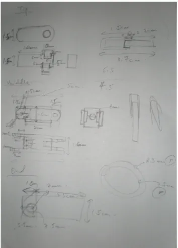
Functional Design stage, a workable design is developed, including a detailed plan for fabricating. Geometric features are determined and dimensions are specified, along with allowable tolerances (Refer to the appendices). Below is the sketch of the design of one finger (Figure 18).
Figure 17: The conceptual design of humanoid finger Distal
Intermediate
Proximal
16
The design of this humanoid finger is based on a 22 year old Chinese man; His height is 169cm, and his weight is 60kg. As we can see from Figure 14, the dimension is included in the design as this design will be drawn out in 3D by using SOLID WORKS. The segments of the finger will be drawn out separately as shown in Figure 19, 20 and 21. These segments will be assembling into one finger (Figure 23). From Figure 23, a spring will be put inside the holes which are located at Distal and Proximal respectively. And the design of the humanoid palm is shown at Figure 22
17
Figure 19: Distal Figure 20: Intermediate
Figure 21: Proximal
Figure 23: Assemble the segments into one finger Hole
Proximal
Intermediate
Distal Figure 22: The palm
18 3.4.3 Production Design
At this stage, the materials will be specified whether they are compatible with the manufacturing process and equipment. Hence, the materials will be selected by using decision matrix. The materials must posses the criteria as follows:
• Strength
Permanence by virtue of the power to resist stress or force • Cost
It includes the price of the material and the cost of fabrication. It is
recommended as low cost as possible in terms of purchasing and fabricate the materials.
• Effectiveness
The rating will be based on the difficulty to fabricate the material. In addition, the ability to resist against corrosion agents such as acids. The more resistant against corrosive, the better it is.
• Weight
The rating is also based on the weight of the material. It is recommended to use as light as possible to reduce the consumption of the power of the motor when it is fabricated.
The ratings are given from 1 to 5.The higher the rating, the better it meets the criteria. The total ratings of the criteria are 30 points.
Table 1[5] at the next page it shows the alternatives of the material to fabricate out the hand:
• Aluminum • Steel • Plastic
By comparing the ratings for each of the materials, Aluminum has the highest rating but it is quite pricy to purchase it. Anyway, the problem is resolved as this material is available at UTP.
19
Material Characteristics Elaboration Points (1-5)
Aluminum Strength Good 3
Cost High 2
Availability Available in lab 5
Effectiveness Non corrosive material
5
Easily fabricated 4
Weight Heavy 3
TOTAL 22/30
Steel Strength High 5
Cost High 1
Availability Available in lab 4
Effectiveness Corrosive material 1
Hard to fabricate 2
Weight Very heavy 1
TOTAL 14/30
Plastic Strength Low 1
Cost Low 5
Availability Not available in lab 1
Effectiveness Non corrosive material
5
Hard to fabricate 1
Weight Light 5
TOTAL 18/30
20
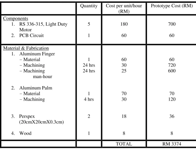
When fabricating the humanoid robotic hand, we also must consider the cost of the components, materials and man-hour. Hence, the total cost of this project is estimated about RM3374. If the humanoid robotic hand is mass produced, the cost will be expected to be less than this value.
3.5 Simulation
The movement of the fingers will be simulated by using SOLID WORKS to identify the constraint position. When the finger is moved, it is predicted that the finger doesn’t move smoothly as too much stress is applied on the spring when bending the fingers. Thus, it consumes lots of power to pull the wires to bend the finger. From there, we have to modify the finger to resolve this problem. At the intermediate part of the finger, the top part is cut off to let the spring “free” to bend (Figure 24). It also reduces lots of
Quantity Cost per unit/hour (RM) Prototype Cost (RM) Components 1. RS 336-315, Light Duty Motor 2. PCB Circuit 5 1 180 60 700 60 Material & Fabrication
1. Aluminum Finger -Material -Machining -Machining man-hour 2. Aluminum Palm -Material -Machining 3. Perspex (20cmX20cmX0.3cm) 4. Wood 1 24 hrs 24 hrs 1 4 hrs 2 1 60 30 25 70 30 18 8 60 720 600 70 120 36 8 TOTAL RM 3374
21
constraint with this design. Hence, the final design of the finger is shown at Figure 25 (right)
Figure 24: Modified Intermediate
22 3.6 Fabrication
If the testing mechanism is successful, the humanoid robotic hand will be fabricated. The first prototype will be called α-Prototype. The mechanism and the movement of the
hand will be recorded. Moreover, the tools which are required in the fabrication are: • Conventional Milling
Conventional Milling is used to reduced the thickness and smoothen the surface of the aluminum.
• Conventional lathe
To reduce the thickness of cylindrical aluminum and produce coupling. Figure 27: Conventional Lathe
23 • Linear Hack Saw
To cut the aluminum into smaller pieces.
• Milling Turret
To shape out the fingers and palm out from aluminum pieces. At the next page, Figure 30 and 31 show that Intermediate and Distal is fabricated by using Milling Turret.
Figure 28: Linear Hack Saw
24 • CNC milling
To cut out the hollow from the palm (Figure 33). Figure 32: CNC Milling
Figure 30: Fabricate Intermediate Figure 31: Fabricate Distal
25 • Wire EDM (Electric Discharge Machining)
To shape the intermediate segment from aluminum pieces. But this process is only done on testing mechanism as it is costly to produce and takes longer time to complete it.
To use all of the equipments which are stated, the student has to book the machine by using Booking Form (Appendices Section).
3.6.1 Software
Softwares which are used in designing and simulating humanoid robotic hand are: a) CATIA P3 V5 R12
b) SOLID WORKS 2006 c) ADAMS 10.0
The pros and cons for each of the software are identified to determined which type of software is suitable in designing and simulating:
26 a) CATIA P3 V5 R12
Pros:
CATIA is able to generate a complex model in 3D. The parts of the humanoid robotic hand can be assembled.
Cons:
Unable to simulate the movement and identify the constraint of the design
b) SOLID WORKS 2006 Pros:
SOLID WORKS can generate 3D model. The parts of the humanoid robotic can be assembled. Can simulate the movement of the hand and identify the constraint. Cons:
Unable to generate a complex model as like CATIA software
c) ADAMS 10.0 Pros:
Can simulate the movement of the humanoid robotic finger. Able to identify the constraint.
Cons:
Only able to generate simplified 2D modeling. A lot of assumptions and analogies when simulate the finger.
It is concluded that SOLID WORKS 2006 is the best choice among the softwares
27 3.6.2 Circuit Board
The rotational of the motor is either clockwise or anticlockwise and it is controlled by the direction flow of the current. Hence, to change the direction flow of the current, the poles of the power source must be changed also. It would be troublesome to change the poles manually every time. Hence, the circuit is built to control the rotations of the motor.
3.6.2.1 Concept of H-bridge
An H-bridge is an electronic circuit which enables DC electric motors to be run forwards or backwards. The concept of H-Bridge is discussed below.
The term "H-bridge" is derived from the typical graphical representation of such a circuit. An H-bridge is built with four switches (solid-state or mechanical). Refer to Figure 36.
When the switches S1 and S4 (Refer Figure 37 left) are closed (and S2 and S3 are open) a positive voltage will be applied across the motor. By opening S1 and S4 switches and closing S2 and S3 switches (Refer Figure 37 right), this voltage is reversed, allowing reverse operation of the motor.
28
Using the nomenclature above, the switches S1 and S2 should never be closed at the same time, as this would cause a short circuit on the input voltage source. The same applies to the switches S3 and S4. This condition is known as shoot-through.
Below is the table that summarizes the operation
Table 3: Summary of the operation of the motor
3.6.2.2 Components of circuit board
The metal–oxide–semiconductor field-effect transistor (MOSFET, MOS-FET, or MOS FET) is a device used to amplify or switch electronic signals. It is by far the most common field-effect transistor in both digital and analog circuits. The MOSFET is composed of a channel of n-type or p-type semiconductor material (see article on semiconductor devices), and is accordingly called an NMOSFET or a PMOSFET (also commonly nMOSFET, pMOSFET).
S1 S2 S3 S4 Result
1 0 0 1 Motor moves right 0 1 1 0 Motor moves left 0 0 0 0 Motor free runs
0 1 0 1 Motor brakes
29 Below is the layout of the circuit using MOSFET.
By comparing the Figure 36 and 40, MOSFET can be act as a “switch”. Moreover, it requires four MOSFETs to control one motor. Although MOSFET can be used to construct H-Bridge, it is not suitable as there are a few limitations as follows:
a) It makes the circuit more complex as each motor requires four MOSFETs. b) More errors will occurred as some of the MOSFET is not stable.
c) A complete circuit requires correct connection for each MOSFET. Figure 38: Symbol for pMOSFET Figure 39: MOSFET
30
Hence, another alternate way to replace MOSFET is L298N (The Dual Full-Bridge Driver).
The advantages of using L298N as follows: a) Simplified the circuit layout
b) One L298N can drive two motors
Figure 42 shows the functions for each pin
Below is the description for each pin
Pin Number Name Function
1;15 Sense A; Sense B Between this pin and ground is connected the sense resistor to control the current of the load. 2;3 Out 1; Out 2 Outputs of the Bridge A; the current that flows through the load connected between these two pins is monitored at pin1
Figure 41: L298N
31
4 Vs Supply Voltage for the Power Output Stages
5;7 Input 1; Input 2 TTL Compatible Inputs of the Bridge A 6;11 Enable A; Enable B TTL Compatible Enable Input: the L state
disables the bridge A (enable A) and/or the bridge B (enable B)
8 GND Ground
9 VSS Supply Voltage for the Logic Blocks. A 100nF
capacitor must be connected between this pin and ground
10;12 Input 3; Input 4 TTL Compatible Inputs of the Bridge B
13;14 Out 3; Out 4 Outputs of the Bridge B. The current that flows through the load connected between these two pins is monitored at pin 15
Pin 6, 11 and 9 requires input voltage of 5V. If exceeded 5V, it might burn up the Bridge Driver. Hence, it must require constant input voltage of 5V.
Thus, KA7805 can solve this problem. The reason is this semiconductor can regulate the voltage of 5V.
Besides it can regulate voltage of 5V, it can also limit the current output up to 1A. Next page is the layout of the circuit for connecting L298N and KA7805.
32 3.7 Testing
Continuation from Fabrication stage, the testing mechanism is tested to ensure that the humanoid finger works properly and smoothly. This stage is quite crucial as lots of problem will be faced if the mechanism does not work properly. If the mechanism does not work well, we have to return to the Designing stage again to modify the design of the humanoid finger. Besides working on the humanoid finger, the circuit board is also tested to ensure that it works well in controlling the motor.
7805
Figure 44: Layout of the circuit connecting L298N and 7805.
Figure 45: The testing prototype to test the mechanism
33 3.7.1 Mechanism of the humanoid finger
When the finger is pulled by the cable, it seems that the finger tends to bend a bit instead of fully bend. Moreover, the finger can’t revert back to its original position when the cable is loosened (Figure 47). Thus, the movement of the finger didn’t perform as well as simulation.
Figure 46: The testing circuit board
34
The cable which is used to pull the humanoid finger is either using guitar string, violin string or nylon string (Fishing string). But these components failed to performed and meet the expectations of the results as:
a) Guitar String
Even the guitar string has high strength but the flexibility of it is quite poor as it is made of wire stainless steel. Hence, it is quite “hard” to pull it as it possess the material properties of metal. After one pull, the shape guitar string is deformed and breaks off.
b) Violin String
The material of making this violin string is the same as guitar string. Thus, the result of it also as same as guitar string
c) Nylon String
It has high flexibility. Hence, it is much easier to pull but the strength of this material is weak. So, the nylon string is much easier to elongate and break off.
3.7.2 Controlling the motor
35
The circuit board is working successfully when it is tested. When a button is pressed, the shaft of the motor is rotating anti-clockwise or vice-versa when another button is pressed.
Hence, it is only the mechanism of the humanoid finger has problem .This has to go back to Designing stage. The improvement of the mechanism is discussed at Analysis and Discussion stage.
3.8 Analysis and Discussion
The problems are identified when an analysis is done on the mechanism:
a) The spring is unable to revert back to the original position due to heaviness of the segments of the finger.
b) The spring tends to “slip” off when the finger is bending. This is also another reason that the humanoid finger is unable to revert back to the original position.
To solve problem (a), the design must be modified to reduce the weight. Figure 49 shows thatthe top part of Distal , certain portion of the solid Aluminium is removed (Figure 49 right). This is to reduce the weight of the finger and also increase the
smoothness mechanism of the finger. Hence, the design of the finger is changed (Figure 50 right).
Figure 49: Modification design of Distal, before (left) and after (right)
36
As for problem (b), the screws will be screwed deeper to tighten the spring. When the spring is tightening, the spring will not “slip off” when the finger is bending.
To solve the problem of selecting the materials for the cable, the string which is made from Kevlar will be selected. The reason of selecting it is as follows:
• More flexible
• Can lift a weight up to 45kg • Not easily worn out
3.9 Documentation
Documentation is the final stage of methodology. The research and results must be properly documented for future references. In addition, the resources are also documented.
Figure 50: Overall design finger. Before modification (left) and after modification (right)
37
Chapter 4: Results and Discussion
Once all of the methodology is completed, the final humanoid robotic hand is produced and the full completed circuit board is completed.
The circuit board is connected to five motors and controls the direction of rotating motors. The motors rotate successfully. It is identified that the force required to fully bend one finger is about 15N. All of the fingers are bent successfully. Since each finger moves in one direction, it has one Degrees of Freedom (DOF). Hence, in total, this
Figure 51: The final result of humanoid robotic hand
38
prototype has five DOF. When the humanoid robotic hand is tested to grasp an object, it tends to slip off.
Chapter 5: Conclusion and Recommendations
As a conclusion of this project, all of the objectives are met and completed. Although it failed to grasp an object, this prototype is able to demonstrate the movement and the mechanism of the fingers. The duration of this project is estimated at about one and a half year to complete all of the methodologies. If more time is given and the cost of the project is not a main problem, the humanoid robotic hand can perform better and analysis can be done deeper.
Since there is room for improvement, this section discusses about recommendations for future of this project:
a) A remote is built to control all of the fingers but the duration of time to complete this task is estimated about 6 months to 1 year. The reason is to learn C++ Language Programming, built out PIC circuit board and testing.
b) Each finger is recommended to embed four motors. Hence, it provides more DOF for each finger. As a result, it can be predicted that it can grasp the object. c) Strain gauge is added to the fingers. Thus, it can sense the types of the object and
apply different forces for different types of objects. For example, a small amount of force is required to grasps an egg.
39
References
[1] Open Press, Los Angeles, CA, 14 August 2007. Sources from http://www.theopenpress.com/?a=articles&code=01&id=185
[2] Naoki Fukaya, “Design of the TUAT/Karlsruhe Humanoid Hand”
[3] F. Lotti et al., “Development of UB Hand 3: Early Results” in Proceedings of the 2005 IEEE, International Conference on Robotics and Automation, Barcelona, Spain, April 2005.
[4] E. Paul Degarmo et al., “Materials and Process in Manufacturing, Ninth Edition”, John Wiley & Sons Inc, 2003, United States of America.
[5] Le Bang Duc et al., “Engineering Team Project: Final Report”, Universiti Teknologi PETRONAS, 2006, Malaysia.
[6] http://en.wikipedia.org/wiki/Humanoid_robot
40
Appendices
41
GANTT
CHART
46