1
FULL LOAD TESTING OF LARGE ELECTRICAL DRIVEN TRAIN
Theodor Loscha
Technical Expert E-LNG
Thomas Matern
Head of Test Engineering Christian Beer Senior E-Drive Expert
Volker Hütten Head of Numerical Design
Norbert Geilich Head of Test Center Siemens Energy Sector
Duisburg; Germany ABSTRACT
A number of tests are carried out during manufacture and after assembly of large turbo-compressor strings. This paper focuses on full load, full speed, and full pressure tests of large electrical driven compressor strings with power consumptions up to 100 MW. Testing of these systems, including not only the motor but the complete VSD system requires careful planning, scheduling and arrangement of the equipment to be tested. Based on the customer’s specific requirements, test procedures need to be prepared and discussed in advance, including the definition of the tests to be performed, the sequence of testing as well as details of the test instrumentation and data acquisition. The tests will be carried out in accordance with the applicable standards, e.g. ASME, DIN, and API to ensure a maximum of quality assurance for the equipment delivered to site. Therefore, such a testing is one of the most important milestones in order to minimize the risk on site. Siemens has built one of the world’s largest test centers for compressor trains. Its infrastructure is specifically designed to accommodate full load testing of large compressor strings with:
• Electrical VSDS driver up to 100 MW coupling power
• Gas turbine drive up to 160 MW coupling power
• Steam turbine drive up to 35 MW coupling power
In its first part, this paper describes the general scope of testing, the methodology and the original equipment to be used for the full load test, i.e.
• Compressor-Motor string on original base frame
• Job transformers
• Job converter including harmonic filters, cooling system
• Job auxiliaries
The second part provides some more details regarding the preparations for the installation of the equipment, the commissioning of the systems and the challenges of testing and releasing a whole system with a high voltage electric set up starting at the connection to the public grid.
Finally, the paper illustrates an example set up for a large electrical driven compressor train, where tests with power consumptions close to 80 MW have been successfully completed.
2 INTRODUCTION
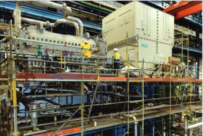
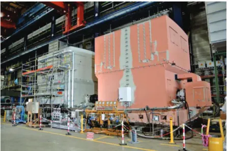
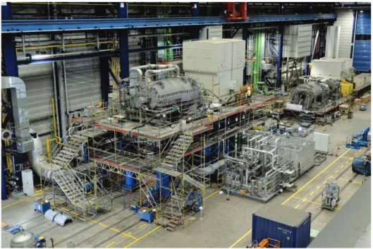
Large compressors in the process industry like Oil & Gas or Air Separation are not only significant energy consumers, but also represent a major part of the investment costs for a new plant. High thermal efficiencies combined with highest reliability, availability and cost effective maintenance of the equipment are therefore essential in order to achieve a most economical plant production. Furthermore, the volume of greenhouse gas emissions emitted to the atmosphere becomes a more and more important benchmark. This leads to a visible trend in the industry to produce the required electrical energy for example by means of a high efficient combined cycle power plants, and then use the generated power for electrical drive systems of large energy consumers. With this combination an operation for many years without interruption can be achieved, while keeping the green house emissions low. An example for a large electric driven train is given in Figure 1.
Figure 1. Example of a 80 MW large electric driven train at the Mega Test Center in Duisburg Operational flexibility is another key criteria for large turbo compressor strings. A combination of an electrical variable speed drive system with an adjustable inlet guide vane control offers a wide operating range. With a proper electromechanical design of the compression string, the achievable speed range can easily reach 70% to 105%. Such a system also offers a high accelerating torque available from a very low speed up to maximum continuous speed of the string. In most cases start up of the plant without flaring is possible which increases the availability of the plant. Electromechanical design means, that motor and compressor are not considered separately, but as one unit or one entire system, which has to be engineered together, keeping in mind all interfaces between the electrical and the mechanical part. For example, the impact of interharmonics needs to be considered to avoid potential issues in terms of torsional vibrations.
In case that a large turndown is required, adjustable IGV’s can be an appropriate method of control. The indicative performance map in Figure 2 shows a general comparison of achievable performance characteristics. The combination of IGV and speed control normally offers the widest range of operation and therefore significantly improves the flexibility of plant operation.
3
Figure 2. Comparison of compressor control methods
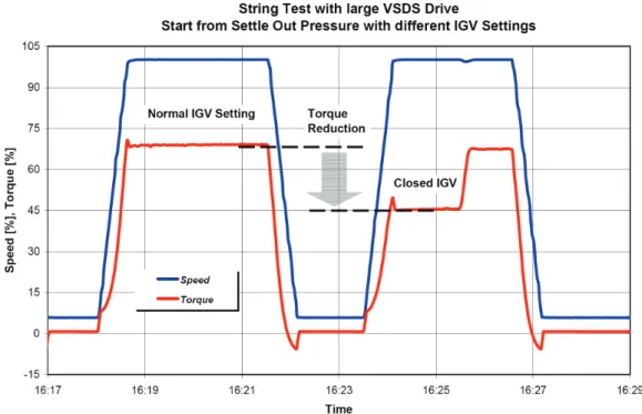
Using adjustable IGV offers another major advantage : The torque requirements during compressor start up will significantly be reduced, thus facilitating a restart from settling out conditions. This has been successfully demonstrated for a large application, with two consecutive starts from settle out pressure, the first start with normal IGV setting, the second start with the IGV further closed. Figure 3 shows the trend curves for torque and speed with the corresponding reduction in torque.
Figure 3. Torque reduction during start up using an adjustable inlet guide vane TESTING OF CORE COMPRESSORS
General Remarks
Following manufacture and assembly, the majority of compressors are subjected to running tests to ensure that the contractually agreed performance characteristics are met.
The type and scope of these running tests are specified by the customer. Options for running tests vary widely, depending on the specific application of the compressor, the installation location and environment, previous experience, and the available budget. If a customer already has identical machines in service, and operating experience with these machines has been good, they may decide not to carry out tests at all,
4
particularly in cases where delivery lead times are very short. If it is important to achieve certain operating points for a special application, however, the customer will probably order a performance test to ensure that the compressor is able to deliver the warranted performance levels. If several compressors of identical design are ordered, the question arises as to whether and to what extent the test scope could be reduced for subsequent machines in the series.
The customer thus always has to make a project-specific, individual decision regarding the scope of testing. The manufacturer can provide support for decision-making by discussing with the customer which scope of testing meets their specific requirements. Ultimately, the questions that need to be answered are as follows: What does the customer want to achieve through testing and/or what are the risks that testing is meant to minimize?
Options for Mechanical Running Tests
Mechanical running tests are performed on the basis of the standard API 617. The mechanical running test for a core compressor is the simplest test variant. Unless otherwise specified, and provided the compressor design allows, this test is carried out in a vacuum, or in air (i.e. open). These two test types are the cheapest variants since they do not require large test set ups.
A closed loop must be set up for compressors whose design does not allow running tests to be carried out in a vacuum or in air. The loop usually consists of interconnecting piping, a test stand cooler and a throttling device, such as valves or flaps. A test gas (helium is frequently used for mechanical running tests) is circulated through the loop, and cooled and depressurized in the loop between the compressor discharge and its suction side.
For the mechanical running test, the compressor is operated at maximum continuous speed for four hours, as per API 617. During this time, bearing temperatures and vibration levels are monitored, and must not exceed the specified limits. The lube oil temperature, and sometimes also the lube oil pressure, is usually varied during the running test. The aim is to ensure that the bearings do not exhibit any offnormal behavior under varying operating conditions. Other supplementary elements, such as a restart immediately after the running test or operation at other speeds, may be additionally specified by some customers.
Options for Performance Tests
Performance tests are usually performed on the basis of ASME standard PTC10. A distinction is made between Type 1 and Type 2 tests. Type 1 tests have to be carried out using the design gas specified in the contract for use during actual operation, while a test gas can be used for Type 2 tests.
Performance tests carried out in the test facility are usually Type 2 tests. Air, N2, CO2, R134a, helium or mixtures of these gases can serve as a test gas. Type 2 tests are performed under comparative conditions, determined on the basis of the specifications in ASME PTC10. Compliance with the comparative conditions ensures that the results of the measurements can be applied to actual operation in the field. Type 1 tests can be carried out within certain limitations and some gases, e.g. hydrocarbons up to butane or CO2. Although this makes running tests significantly more complex, particularly in terms of safety regulations for combustible gases, they can however still be carried out in the test facility.
In the case of large compressors, compliance with the minimum straight lengths of pipe leading up to the compressor inlet nozzle as required in ASME PTC10 may be challenging. In machines with nozzles downwards, in particular, this would require very high test stands, something which is possible but would significantly increase the cost and also the setup times for the running tests. Vaned elbows, which can be installed on the suction side of the compressor and ensure suitable inlet flow conditions without negatively influencing the results of the measurements, project a much shorter distance outward from the machine and have therefore proven useful for this purpose.
5
TESTING OF COMPLETE UNITS (CORE COMPRESSORS WITH OTHER COMPONENTS) General Remarks
In addition to testing a core compressor, customers may sometimes wish to test other components together with the compressor. Compared to the tests for the core compressor, tests that also include additional components are described in only very rudimentary fashion in API 617, and for good reason. As shown above, a wide range of possible variants exists as regards the scope of running tests for core compressors. This applies even more so when additional components are included. In any case, detailed coordination between customer and manufacturer is required to determine which components are to be incorporated into the tests, and to what extent. Ultimately, the incorporation of additional components has a significant effect on test cost, as well as influencing lead times.
Additional Components
Components to be additionally incorporated into a test would usually be restricted to the manufacturer’s scope of supply. Starting at the core compressor, this would primarily concern the drive and other components located on the baseframe; i.e. in addition to the baseframe itself, possibly a gearbox, a seal gas panel and/or a shaft jacking system. Other components may also be associated with the drive, for example a transformer or converter in the case of a motor, and possibly a condenser in the case of a steam turbine. Another essential component, apart from the baseframe, is the lube oil unit.
The customers also occasionally wish to include instrumentation and control (I&C) components, even if they are not part of the manufacturer’s scope of supply and have to be provided by the customer. Although the incorporation of additional I&C equipment is possible to a certain extent, the question arises as to whether the expenditure is justified. Since the I&C equipment has to be specifically adapted to the test conditions, the benefit of including it in the test may be limited in terms of subsequent on-site installation of the compressor. Scope of Complete Unit Tests
The options available for mechanical running tests and performance tests already outlined above likewise apply for complete unit tests. Limitations may apply with regard to the performance tests, however, depending on which comparative conditions are required. The actual contract configuration may not offer the same flexibility as a test set up with a test stand drive. This being the case, it may be beneficial to carry out the performance test with just the core compressor first. Depending on the test setup, the subsequent mechanical running test can then be carried out immediately afterwards, with moderate effort and expense. This ensures that the core compressor meets the specified requirements at the time of the complete unit test, thereby avoiding any critical impact on lead time in the event of deficiencies being identified when the complete unit is tested, especially when configurations are complex and tests are conducted at high output levels.
Complete unit tests are usually specified as full-load tests, although not in the sense of a performance test but as a means of demonstrating that the system can be operated at the corresponding output. Full load is normally defined as the output at the guaranteed operating point. If a mechanical running test has already been carried out on the compressor, the duration of the complete unit test can be reduced. This makes particular sense in the case of high outputs, for example in order to reduce the load on the local power grid when electric motor drives are being tested. Complete unit tests are often accompanied by a need for more extensive measurements. Once a complex test configuration of this kind has been set up, a wide range of measurements are expected to supply all kinds of useful information for when the equipment is subsequently installed at the customer’s site. These include, for example, noise measurements, vibration measurements on the frame and support structure, or measurements of torsional vibration.
6 Usefulness of Complete Unit Tests
With extensive and complex complete unit tests, in particular, the question arises as to how far such tests are useful to the customer. For with this type of test, the test costs can reach 5-10% of the contract value and the delivery lead time can be extended by several months. Anyway, individual components, such as the lube oil unit or drive, are generally tested separately in advance, like the core compressor.
What a complete unit test does offer is the possibility of detecting and eliminating potential errors at the interfaces between the individual components. In addition, complete unit tests often offer the only opportunity for operating the equipment under full load in the test stand, particularly in the case of high-capacity compressors. With regard to cost and lead time, the customer has to weigh up what kinds of difficulties could occur, with what probability, at what point in the project, and what the consequences would be. These deliberations may lead to the decision that even complex complete unit tests, requiring commensurately high levels of cost and effort, are justified, compared to a scenario later on in which problems arise on site (i.e. at the installation location) and lead to massive delays for the overall plant.
CHALLENGES ARISING WITH COMPLETE UNIT TESTS General Remarks
As has already been explained, the requirements and hence the type and scope of complete unit tests depend on the individual project, and can therefore vary widely. Unlike the tests conducted on the core compressor, which are integrated into normal manufacturing processes, complete unit tests may involve significantly longer planning and setup times, and hence also highly specific requirements regarding the preparation of such tests. To take account of this situation, it may be useful to project-manage complete unit tests on a separate basis. The task of such a ‘Test Project Management’ is to ensure, starting from receipt of the order, that all necessary test preparations (e.g. ordering of additional components, internal and external planning, coordination with suppliers, etc.) are executed in time. In addition, the Test Project Management acts as a central point of contact for the overall Project Management on all issues relating to the tests specified for the respective order.
Technical Challenges Arising with Complete Unit Tests
The technical challenges arising during the preparation and execution of complex complete unit tests depend on the type and scope of the tests. Ultimately, they arise out of the kinds of interfaces that are specific to such test environments. Key interfaces in the test environment are the power supply, loop connections and the machine train setup, and can also include the integration of I&C equipment.
The power supply is governed by conditions at the actual place of installation and must be replicated when configuring the test stand. For gas turbines, for example, this means that fuel gas must be supplied at adequate pressure, and appropriate air intake and exhaust gas connections must be provided. In the case of steam turbines, it must be checked whether the specified steam parameters and flows can be achieved. Where electric drives are used, along with contractually specified converters and transformers, additional components may be required, such as a matching transformer or switchgear unit. Further equipment may also be needed, such as a premagnetizing transformer, to eliminate any effects on the local power grid. Depending on the infrastructure already available at the test facility, the installation of a suitable power supply may be comparatively expensive.
The process connections are usually modeled using equipment already available at the test facility: e.g. coolers, piping and throttling devices. Since the inventory available at the test facility cannot cover all possible requirements, individual pipe components may sometimes have to be specified and procured, depending on the specific test in question. This is particularly the case when test pressures are high or test gases are employed that could form an explosive atmosphere. Pipe procurement lead times, which depend on the necessary pipe dimensions, also have to be taken duly into account.
7
The configuration of the machine train on the test stand generally differs from the on-site installation conditions. The frame with the compressor and drive is usually secured to a test stand support structure, which is, in turn, attached to the foundation. Depending on the type of tests to be carried out and/or the test setup, more or less extensive calculations are carried out to demonstrate that the setup meets the corresponding requirements.
Organizational Challenges
In addition to the technical challenges, there are a number of organizational challenges that have to be met, particularly by the Test Project Management. In terms of scheduling, it must be ensured that additionally required equipment is specified and ordered in good time. However, the contract components that have to be incorporated into the test stand must also be delivered to the test facility in time for the running tests since delivery schedules are usually not geared to the dates selected for such tests. In addition to the equipment itself, support during setup and commissioning may be required from specialist personnel provided by the respective manufacturer, for example in connection with transformers, switchgear units or converters. The required manpower must be ordered and planned in good time. As far as power supplies and operating fluids (e.g. test gases) are concerned, suppliers must be consulted in good time to minimize the risk of supply shortages.
Since complex test stands constitute a construction site in themselves within the overall test facility, a separate health, safety and environmental analysis may be required. Such an analysis would initially need to review the responsibilities of the persons involved in the setup process, as well as the extent to which access controls are required, and whether separate hazard assessments should be drawn up. This applies particularly to test stands in which different suppliers and/or trades are involved.
OPTIMUM SCOPE OF COMPLETE UNIT TESTS
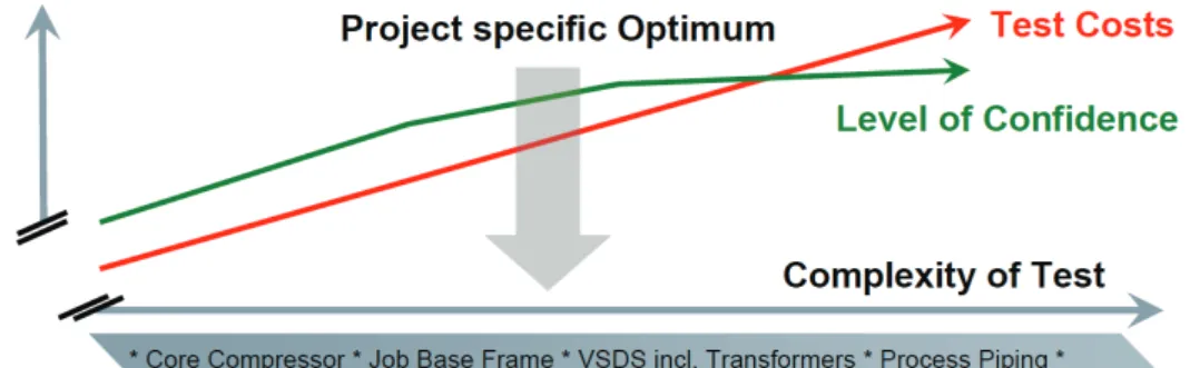
As already explained, complete unit test requirements – and hence the type and scope of complete unit tests – depend on the individual project. What may be important and appropriate for one project might prove to be completely overdimensioned for another project. The first and most fundamental challenge in connection with complete unit tests is to discuss individual requirements with the customer as early as during the proposal phase, and to identify the risks to be mitigated by the tests and how this objective can be achieved at reasonable cost. Figure 4 illustrates this task of optimizing the test scope.
The aim of the tests is to ensure that the equipment can subsequently be placed in service on-site in a reasonable time, and operated without difficulties. Difficulties encountered during startup and operation may be expensive and time-consuming to correct, and may lead to loss of production. Complete unit tests, which in some ways constitute a kind of advance commissioning, are designed to reduce the probability of such difficulties. Depending on the installation location and the infrastructure present at that location, it is indeed possible that difficulties that could be remedied elsewhere without great expenditure and effort turn out to be costly and time-consuming to correct. Individual customers’ assessments of the required scope of testing will therefore vary widely.
Some customers want to test “as many things as possible”. In such cases, it is important to be clear about the limits of complete unit tests. In all cases, plant components are taken out of their specified configuration and installed in a test environment. Although extending the scope of testing allows interfaces to be moved, and certainly optimized too, they cannot be completely avoided. If, when determining the scope of testing, interfaces are created which require complex and/or costly adaptation to the test environment with no direct benefit for subsequent on-site commissioning, the scope of testing should be reviewed and revised. With regard to test cost, restrictions imposed by the available infrastructure can lead to significant increases in expenditure. From a technical viewpoint, such restrictions can generally be overcome, but the cost may not be justified in terms of the additional benefit to the customer.
8
Orders involving several machines of identical design frequently offer opportunities for optimization, for example by reducing the scope of testing for subsequent machines, or by using identical components in several tests. The scope of testing can likewise be appropriately divided among different machines; for example, a performance test and mechanical running test can be performed on the first compressor as the core compressor, and the mechanical test can then be carried out directly in combination with a string test on the second compressor.
Figure 4. Optimizing test scope and costs TEST CAPABILITIES OF MEGA TEST CENTER IN DUISBURG
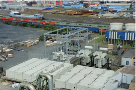
The sod-cutting ceremony for the Mega Test Center in 2006 marked the start of construction of a unique test facility as can be seen in Figure 5. The center is designed for performing large and complex tests on compressors with various types of drives and auxiliary equipment. The test facility and its associated infrastructure have been continuously in operation since the first running test performed there in 2008. The Mega Test Center building is 180 m long, 40 m wide and 35 m high, with a crane hook clearance of 26 m that allows test stands to reach a significant height. Among the center's fleet of cranes are two 350-ton cranes, providing the ability to lift components with a total weight of up to around 700 tons. A direct connection to Europe’s largest inland port allows direct transfer of tested units onto ships, for shipment by sea via Rotterdam.
9
The Mega Test Center can accommodate up to six “mega trains”, e.g. large air compressors, LNG refrigerant compressors or around ten smaller test stands simultaneously. Suitable power supplies are provided for the different types of compressor drives. Large electric motors can be connected to the public grid via an in-house 110 kV connection, allowing motors rated up to 100 MW to be used. For gas-driven compressors, the test center design was based on a 160 MW heavy-duty gas turbine with a fuel gas consumption of approximately 10 kg/s. Main steam is supplied via a steam pipeline that links the Mega Test Center to a nearby municipal power plant. The power plant’s turbine-generator can be run down to provide steam for testing when required. Steam is supplied at up to 100 bar and 500°C, enabling outputs of around 35 MW to be achieved. The power delivered to the compressor(s) via the drives naturally has to be dissipated into the environment in the form of thermal energy. Permanently installed cooling systems with a heat-removal capacity of 100 MW are available for this. Although the contractually specified lube oil unit is generally utilized in complete unit tests, the test facility also has a dedicated oil system with a capacity of approximately 4500 l/min at a maximum pressure of 16 barg. Test gases are supplied via dedicated tanks. A recycling system has been installed for the test gas R134a so that the gas can be recovered on completion of the tests. This cryogenic system enables the gas, which is otherwise damaging to the climate, to be reutilized in an environmentally friendly manner. In addition to its stationary systems, the Mega Test Center also has a wide array of mobile equipment, such as test stand motors, gears and coolers of various sizes, as well as systems for recording measured data.
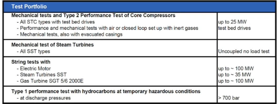
All this means that the center can carry out a wide range of running tests with no need for additional infrastructure. Moreover, with an indoor testing area of 4,400 square meters and an outdoor area of 50,000 square meters, the center has enough space to meet any customer requirements that go beyond the infrastructure already available. Figure 6 summarizes the test portfolio.
Figure 6. Summary of test portfolio
EXAMPLE OF A COMPLEX COMPLETE UNIT TEST WITH ELECTRIC MOTOR DRIVE General Remarks
The selected example is based on an electric-motor-driven compressor train with a capacity close to 80 MW. Because testing involves more than one identical compressor train, the customer has specified a so-called “back-to-back test” of the electric drives, in addition to the actual complete unit test of the compressor with drive and auxiliaries. This involves testing one of the electric drives while it drives the other (the second drive acts as a generator). The two motors are positioned opposite one another and are coupled directly.
A back-to-back test is often required for cases in which the compressor and the electric motor are manufactured by different companies. The test is aimed at preventing any difficulties at interfaces between the drive and the compressor, and enabling deficiencies or areas for improvement to be pinpointed. Set up of a back-to-back test is given in Figure 7. If the compressor and drive come from the same manufacturer, a
10
back-to-back test is not necessary since the responsibilities are clear from the customer’s point of view. Nevertheless, some customers attach importance to having a separate test of the motors.
Figure 7. Back to back test set up
Following the back-to-back test, the motor deployed as the drive is used for the complete unit test of the compressor train. In addition to the actual string itself, the contract lube oil unit, seal gas panel and shaft jacking system are also used in the test. The string test is specified as a full-load test, but it is not a performance test. Instead, the purpose of this test is to demonstrate that the entire system is capable of producing and utilizing the specified output. Both thermodynamic and mechanical tests are carried out on the core compressor in advance of the string test.
TECHNICAL ASPECTS OF THE PLANNING AND PERFORMANCE OF TESTS ON LARGE MOTOR-DRIVEN COMPRESSORS
Machinery Dynamic Aspects of the Motor
In order to achieve acceptable lateral and torsional vibration levels during a full load string test of an large electrical motor driven compressor train machinery dynamic design aspects have to be considered adequately already in the earliest stage of the project. Therefore a proper rotordynamic design of the motor rotor is an essential task. In addition the motor, converter and operating speed set-up of the entire train to avoid torsional resonances within the operating speed caused by interharmonic excitations generated in the converter is an important design aspects.
Rotordynamic Design of the Motor Rotor
In principle the rotordynamic design of the motor rotor has to fulfill the design criteria as specified in the API 541. A multiplicity of influencing parameter has to be considered in such an analysis in order to achieve a acceptable vibration levels and a reliable motor design.
Main influencing parameter are as follows:
• Motor rotor geometry (including masses and stiffnesses)
• Damping and stiffness properties of the radial bearings
• Operating speed range
• Unbalance forces distribution
• Thermal rotor bending effects
11
• Bearing pedestal properties
• Steel frame and/or concrete foundation properties
Especially support effects caused by the bearing pedestal and the foundation and the thermal deflection of rotor and stator components are of paramount importance for large motor designs. Nevertheless all influencing parameter have to be considered most accurately.
Torsional Design Set-up of Converter-Motor-Compressor Train
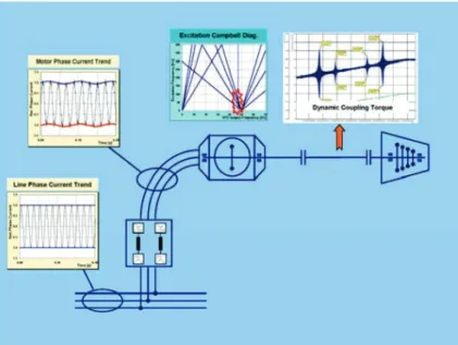
For a reliable train design the torque transmitting elements of the entire train must be designed in order to withstand the stationary operating torques at normal operating conditions. In addition also dynamic torques during start-up, and during electrical fault conditions, like short circuit conditions, ect., have to be transmitted. However, during operation of compressor trains by a variable speed drive system (VSDS), integer and non-integer harmonic currents, also called interharmonics, are generated in the frequency converter. As illustrated in Figure 8 variable speed drive systems rectify alternating line current (AC) of 50 Hz or 60 Hz, to direct current (DC), and invert the DC to a variable frequency AC current in order to operate the motor at variable speeds. As illustrated the electrical conversion from line side to the motor side, quite small harmonic distortion of the inverter output current causes forced torsional vibration. Due to small excitation amplitudes, this is outside the resonances of a well endurable load for the train components. Unfortunately, the vibration is amplified when the excitation frequency of torque ripples match a torsional natural frequency (TNF) with a suitable mode shape to excite the mechanical train.
Figure 8. Electro-Mechanical Interaction
If a resonance with an interharmonic excitation is detected and countermeasures are found to be necessary, one can today choose from a wide range of proven alternatives. These can be sorted into one of the following categories:
• Torsional damping increase
• Torque excitation reduction
• Torque transmitting components fatigue capability increase
• Avoiding of torsional resonance in operating speed range
Taken into account the pros and cons of the well known alternatives the most reliable strategy is to avoid torsional resonances within the operating speed range. This design concept of selecting converter type,
12
motors number of pole pairs and corresponding operating speed range is described in detail in Hütten et. al. (2012). For large VSDS driven trains 12-pulse LCI are typically used. The design concept for an LCI fed motor can be explained as follows:
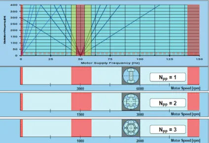
First of all the mechanically relevant harmonic and interharmonic excitations have to be well understood (see Figure 9). Electrical motors can be built in 2, 4, 6, … pole design (equivalent to number of pole pairs (NPP) of 1, 2, 3, …) and this leads to operating speed of:
nop = (fdo / NPP) *60 (1)
nop = Motor operating speed fop = VFD output frequency NPP = Number of pole pairs
Therefore, a motor with a number of pole pairs of 1 runs with supply frequency. Whereas a motor with a number of pole pairs of 2 at half and with a number of pole pairs of 3 at one third of the supply frequency accordingly. This is an essential fact in order to find resonance free train design solutions within this new design concept.
Based on these considerations, the electrical supply frequency ranges which should be avoided are separated. In addition, the ranges of motor supply frequency without resonances caused by the inverter operation are identified and can be used for designing compressor trains. The determined exclusion ranges are transferred into a motor speed related diagram for the chiefly used number of pole pairs 1, 2 and 3. Focussed on the most relevant exclusion range of the resonance conditions caused by interharmonics, it becomes obvious that the center of the most important exclusion range shifts from 3000 rpm to 1500 rpm and finally to 1000 rpm for a number of pole pairs of 1, 2 or 3, accordingly.
Figure 9. Exclusion Ranges Transferred into Motor Speeds.
Figure 10 collects all the relevant information in order to avoid torsional resonances caused by a 12-pulse LCI operation. The allowable speed ranges are marked in green, whereas motor speeds which should be excluded are marked in red.
13
Figure 10. Bar Diagram of Motor Speeds for 12-puls LCI
Currently a 4-pole motor design operated at frequencies higher than 60 Hz represents an uncommon design in the turbomachinery industry. Nevertheless, it offers the opportunity of a torsional resonance free operation by using a reliable standard design. Based on this diagram it is obvious for an operating speed range between 2500.rpm and 3500.rpm to use a 4-pole motor design.
For the mentioned example of the large VSDS system the calculated and therefore expected torsional resonances caused by interharmonic excitation were successfully verified during testing. During Back-to-Back testing of the motor and also during string testing of the motor compressor train a resonance free operating speed range has been demonstrated.
Electrical Components and required Infrastructure
Variable speed drive systems in the sizes mentioned in this paper are of modular design and most of the components are required to execute a complete unit test in a test facility as shown in Figure 11. The following major components of the Variable speed drive system (VSDS) must be shipped and installed:
— Transformer and HV switchgear
Converter transformers match the distribution line voltage to the converter supply voltage, provide fault limiting reactance and will isolate the drive from the power system. The line supply voltage and frequency in the test facility may differ to the actual planning levels at site. In this case it might be required to install matching transformers for the testing period to allow the use of job equipment to the highest extend possible. To control and protect the drive equipment a HV switchgear and additional protection equipment is required for the testing period
— Power modules with pre-installed drive, control and cooling equipment
In the described power range the load commutated inverter (LCI) is still the common choice in the Industry and the LCI is installed in a power module to allow easy transport to the test facility as well as afterwards to the plant site.
For a compressor string in this power range, additional electrical components are required such as: Excitation system for the synchronous motor, cooling equipment for the LCI and LV distribution and control equipment for the compressor string. These components are also needed for the set up of the complete unit test and therefore need to be shipped and installed at the test facility. The use of power modules reduces the installation work significantly and is a common industry practice. The power module installation and commissioning is a major task and needs to be planned and executed similar to the actual work site during a later phase of the project.
14 — The synchronous motor
For large e-driven compressors the typical choice is a synchronous motor with a cylindrical rotor and a brushless exciter. The LCI fed synchronous motor for the given example is water cooled with the cooling water supply provided by the test facility. The synchronous motor is directly coupled to the compressor without gear.
— Harmonic filter
Frequency converters represent nonlinear loads for the power system and as such produce harmonic currents and reduce the power factor as a function of the motor speed. The harmonic filter system design must cover the unique requirements in the test facility as well as the requirements at plant site. It is required to design the harmonic filter in a way to cover both cases with minimum adjustments necessary. A harmonic filter study and measurements are mandatory and in most cases must be discussed in detail with the electrical utility company prior to any testing. The measurements of the total harmonic distortion during the tests will prove the simulation models and design of the harmonic filter for the test site and is another step to reduce design risks for the site installation.
Figure 11. Arrangement of Electrical equipment for back to back and full load string testing Mechanical Setup of Motors/Compressor Train
For the back-to-back test, the motors are secured as directly as possible to the Mega Test Center foundation. Depending on the position of the oil system used, however, the specified runoff elevation must be maintained, which may require, as a minimum measure, the provision of a low support structure with steel beams. Although the motors can, in principle, be set up at any desired location in the Mega Test Center, the requisite cable runs between the electrical equipment in the outdoor area and the motors themselves should be taken into consideration. In the selected example, the motors are placed as close as possible to the electrical installations in the Mega Test Center, ultimately separated only by the wall of the hall, through which the cable penetrations pass.
The refrigeration compressor on which the example is based weighs well over 200 t. The motor alone weighs over 100 t. In light of these weights, a design with separate baseframe for compressor and motor may be selected, which also necessitates dedicated support structures for each. In the selected example, the compressor nozzles point downwards. Combined with the large suction nozzle size of around 2 m, this means that a compressor setup height of 3-4 m is required. Vaned elbows – already mentioned in the section on performance tests – are used on the suction side of the compressor in this case too, to ensure a compact inlet piping configuration. Depending on the compressor frame height, the height of the motor support structure is thus approximately 5-6 m. At the Mega Test Center, a modular system, which includes among other things 3-meter-high steel columns around 1 meter in diameter, is used for the support structure.
15
The columns have end plates which allow them to be fastened to the building foundation at one end and to the baseframe at the other. The columns are additionally backfilled with concrete. The compressor and motor are mounted on these columns. The motor is placed on two rows of columns, each row consisting of four pairs of columns, i.e. 16 columns in total. The dynamic stiffness of the planned test stand are determined by finite element analysis to analytically verify the structural stability of the motor support structure. In addition, the dynamic behavior of the motor, including the motor frame, is analyzed, and an analysis of load-bearing capacity under short-circuit conditions is carried out.
The connection of the compressor to the closed loops permanently installed at the Mega Test Center determines the location of the test stand for the compressor, and hence the string test. The operating mode of the closed loops can be adapted for individual applications by inserting blanking plates. The four 25-MW coolers can be operated in parallel or in series, and can also be assigned to completely separate loops. In the case under consideration, three coolers are operated in parallel. A connection to the closed loop is provided on the discharge side of the compressor, while there are two connections to the closed loop on the suction side, these two connections discharging into a header that leads to the compressor inlet. Metering pipes with orifice plates are incorporated into the piping of the closed loop for determining mass flow. The connecting piping between the compressor and the closed loop is either part of the existing test facility equipment, or is specially manufactured for the test in accordance with the required dimensions and pressure stages. Since, during running tests of compressors for LNG applications, the outlet temperatures are significantly higher than under design operating conditions, thermal expansion must be duly accounted for, especially in the piping on the discharge side of the compressor. The general arrangement is given in Figure 12.
Figure 12. Arrangement of the compressor string including job lube oil unit Test Operation
Due to the expected high outlet temperatures, the compressor must be designed for these running test conditions from the start; i.e. the test conditions must be at least approximated during the proposal phase and taken into account in the compressor design. In the course of order execution, these test conditions are reviewed, slightly adapted if necessary, and incorporated into the test procedure. In contrast to the standard requirement in API 617 that the test procedure be made available at least six weeks before the test, a somewhat longer lead time is recommended for complex tests, to give all those involved in testing sufficient time and opportunity to familiarize themselves with the type and scope of the planned tests.
16
The requirement that not only full load but also the outlet pressure specified for the guaranteed operating point be reached can lead to comparatively unusual test gas mixtures, such as R134a and helium, for example. Due to the high outlet temperatures reached during running tests, the seal gas system may need to be supplemented, for example by providing additional cooling of the primary seal gas. On startup of the compressor train for the running test, possible hold points for compressor heat soaking should be taken into account, particularly for large compressors. These hold points may be specific to the test, and may therefore require separate consideration with regard to the mechanical setup, as well as the electrical operating mode, for example as regards operation of the harmonic filter of the converter. Once the speed specified for the operating point has been reached, the suction pressure and gas composition, and possibly also the inlet guide vane position, are adjusted in order to obtain the desired operating point at full load. The actual test period starts once the full-load operating point is reached. The startup process is not part of the demonstration for the customer as conditions in the test environment differ significantly from normal operating conditions and are therefore specific to the test. The interests of the local electric utility/grid provider regarding times of day and days of the week, as well as load gradients, should be taken into account when determining the load profile for the running test.
ORGANIZATIONAL ASPECTS General Remarks
The preparation and execution of large and complex compressor tests involving electric motor drives necessitates coordination of a large number of different trades, and hence also many different people. In addition to the specialists involved in electrical installation work, such as for the transformers, switchgear unit or converters (including harmonic filters), other activities also have to be performed such as the erection of temporary foundations, installation of a cooling water supply, provision of additional lightning protection where necessary, and protection of the entire test installation against unauthorized access.
The actual test stand, with support structure, power and operating fluid supplies and connections to the closed loop, has to be erected in the hall of the Mega Test Center. Piping must be adapted and erected in situ, a large quantity of scaffolding set up, the motors connected, and additional switchgear cabinets installed. Subcontractors are used for many of these activities. These subcontractors have to be supervised and monitored, not only to ensure performance of the work on schedule and in accordance with specifications, but – in the case of activities in and on the Mega Test Center – also to ensure compliance with corresponding safety regulations. In addition to the trades directly involved in setup of the test stands, a large number of other people are naturally also involved in the planning and setup process, both internal personnel (e.g. in manufacturing or project management) and external providers (e.g. if additional engineering services are purchased from outside).
Scheduling
With complex tests, an initial intensive phase of activities occurs immediately after receipt of the order. During this phase, the scope of testing has to be reconfirmed and reviewed, particularly with regard to long-lead-time orders and the associated specifications. Delivery lead times for a matching transformer or switchgear unit, for example, can be as long as 12 months. This means that such components have to be ordered early on. If, for example, additional foundations have to be cast for the test installation, the season in which the test preparations occur must be taken into account when planning the start date for these activities. Foundation work may have to be brought forward in order to avoid unplanned, weather-related delays. It must additionally be taken into account with all of these activities and orders that the respective components have to be specified, proposals obtained from different manufacturers, and these proposals compared, before the actual ordering process, which is ultimately decisive in determining the delivery lead time, can take place.
17
The second intensive phase runs from the start of the setup process to the actual running test itself. The individual trades have to be coordinated and project progress monitored on the basis of a suitably detailed project schedule, in order to be able to take prompt action in the event of difficulties. During this phase, leading up to the running test, the schedule becomes increasingly detailed. During the setup and commissioning phase, contact between those involved becomes more intensive as a result of regular project meetings.
Safety Aspects
Given the number of external personnel involved in setup, as well as the nature of the electrical activities, it is important that responsibilities for safety be clearly defined from the start. Overall responsibility for the different areas, as well as responsibilities for providing briefings, issuing work permits and controlling access, must be clearly assigned. Since setup takes place at the Mega Test Center, the test facility manager, and the test project manager assigned by the latter to the individual test, are also responsible for safety. However, the electrical installation activities, in particular, constitute in themselves a site that is separate from the remainder of the test stand, with its own rules and responsibilities. A separate ‘Site and Commissioning Management’ must be appointed for these activities, with responsibility for safety on the site.
Supply of Power and Operating Fluids
In addition to electric power, the main items to be supplied are operating fluids such as test gases, cooling water, seal gas and compressed air, and lube oil. As regards power – i.e. in this case the supply of electricity – it must be ensured that local utilities and grid operators are involved in the project from the start. This ensures that the required power will be available on the day of the test, and also that any possible interference with the local grid caused by the test set up will be minimized.
As far as the test gases are concerned, the procurement of large quantities of helium, in particular, may take a long time. The world market is currently under strain, and suppliers are frequently able to meet only part of customers’ requirements. In light of this issue, the running test conditions will naturally be reviewed again to examine whether any alternative options are available. However, if it is not possible to switch to other test gases, given the specified boundary conditions in terms of load and outlet pressure and the compressor design concerned, potential suppliers must be contacted at a sufficiently early stage to ensure that they are promptly notified of requirements, and that appropriate quantities of helium are reserved.
Compressed air or nitrogen is required by certain compressor train components; for example as separation gas between the compressor bearings and the dry gas seal. The Mega Test Center is connected to the Duisburg plant’s compressed air supply system. In addition, the center is equipped with supply lines for large volumes of nitrogen at pressure levels up to 32 bar. For smaller quantities, a 240-bar high-pressure line, usually used for compressor leak tests, is available. If the contract lube oil system is used in the test, prompt procurement of appropriate volumes of oil is necessary. Delivery lead times are not critical in this case. The date of ordering should be carefully considered, however, since lube oil is usually supplied in drums, which should not be stored on site for an unnecessarily long period, particularly where large quantities are involved. Previous Experience
Figure 13 shows an example trend curve for a large complete unit test. The string was tested up to the motor rated power and maximum continuous speed. Shut down was followed by two restarts from settling out pressure. All results of the test met the corresponding acceptance criteria. Auxiliary systems of the Mega Test Center, e.g. cooling systems or the interface to the public grid worked properly and as predicted during the test planning phase.
18
Figure 13. Full load, full speed, full pressure string test including a restart of settling out pressure Further extensive complete unit tests are planned for the near future. As with all complex projects, retrospective reviews allow potential for further improvements to be identified in certain areas. A “Lessons Learned” process is employed on a systematic basis to ensure that appropriate improvements are implemented, delivering further benefits for future tests and customers alike.
SUMMARY AND CONCLUSIONS
For large applications, testing requirements will certainly exceed the usual standard of a mechanical running tests according to API 617. The aim is to make sure that the equipment can subsequently be placed in service on-site in a reasonable time, and operated without difficulties. This may lead to additional contract equipment to be included as part of the test set up as well as the need to run the test at full load.
All these extended requirements have to be carefully discussed and agreed upon during the bid phase as impact on costs as well as delivery times may be significant. Once the order is in, preparations for the tests already start as procurement of the equipment needed, as well as erection and commissioning at the test facility will require some time.
Based on an example for a large electrical driven compressor train, technical aspects of the planning and performance of a full load test are described. This includes machinery and rotordynamic aspects, the electric and mechanical set up as well as organizational and safety aspects.
For the given example the compressor train was successfully tested up to the motor rated power close to 80 MW. The test results were in accordance with the anticipated values and acceptance criteria. The infrastructure of the Mega Test Center including the interface to the public grid demonstrated to work properly as predicted during the planning phase of the test.
19 NOMENCLATURE
AC = Alternating current DC = Direct current
EPC = Engineering and procurement contractor fdo = VFD output frequency [Hz]
fl = Electrical line frequency [Hz] I&C = Instrumentation and control LCI = Load commutated inverter LNG = Liquefied natural gas
nop = Motor operating speed [rpm] NPP = Number of pole pairs [-] TNF = Torsional natural frequency VFD = Variable frequency drive VSDS = Variable speed drive system REFERENCES
API Standard 617, 2002, “Axial and Centrifugal Compressors and Expander-compressors for Petroleum, Chemical and Gas Industry,” Seventh Edition, American Petroleum Institute, Washington, D.C.
ASME PTC 10, 1997, “Performance Test Code on Compressors and Exhausters”, The American Society of Mechanical Engineers, New York
Hütten, V., Beer, Chr., Krause, T., Demmig, S., 2012 “VSDS Motor Inverter Design Concept for Compressor Trains avoiding Interharmonics in Operating Speed Range”, Proceeding of the Forty-first Turbomachinery Symposium, Turbomachinery Laboratory, Texas A&M University, College Station, Texas.
BIBLIOGRAPHY
API Standard 684, 2005, “API Standard Paragraphs Rotordynamic Tutorial: Lateral Critical Speeds, Unbalance Response, Stability, Train Torsionals, and Rotor Balancing,” Second Edition, American Petroleum Institute, Washington, D.C.
ACKNOWLEDGEMENTS
The authors would like to thank the management of Siemens AG for authorizing the publication of Full Load Testing of Large Electrical Driven Train.