Florida International University Florida International University
FIU Digital Commons
FIU Digital Commons
FIU Electronic Theses and Dissertations University Graduate School
11-1-2019
Corrosion Durability of a Nano-Particle Enriched Zinc-Rich Coating
Corrosion Durability of a Nano-Particle Enriched Zinc-Rich Coating
System For Highway Steel Bridges
System For Highway Steel Bridges
Saiada Fuadi Fancy
Saiada Fuadi Fancy, sfanc002@fiu.edu
Follow this and additional works at: https://digitalcommons.fiu.edu/etd
Part of the Civil Engineering Commons, and the Structural Engineering Commons
Recommended Citation Recommended Citation
Fancy, Saiada Fuadi, "Corrosion Durability of a Nano-Particle Enriched Zinc-Rich Coating System For Highway Steel Bridges" (2019). FIU Electronic Theses and Dissertations. 4344.
https://digitalcommons.fiu.edu/etd/4344
This work is brought to you for free and open access by the University Graduate School at FIU Digital Commons. It has been accepted for inclusion in FIU Electronic Theses and Dissertations by an authorized administrator of FIU
FLORIDA INTERNATIONAL UNIVERSITY Miami, Florida
CORROSION DURABILITY OF A NANO-PARTICLE ENRICHED ZINC-RICH COATING SYSTEM FOR HIGHWAY STEEL BRIDGES
A dissertation submitted in partial fulfillment of the requirements for the degree of
DOCTOR OF PHILOSOPHY in
CIVIL ENGINEERING by
Saiada Faudi Fancy
To: Dean John L. Volakis
College of Engineering and Computing
This dissertation, written by Saiada Fuadi Fancy, and entitled Corrosion Durability of a Nano-Particle Enriched Zinc-Rich Coating System for Highway Steel Bridges, having been approved in respect to style and intellectual content, is referred to you for judgment.
We have read this dissertation and recommend that it be approved.
Norman D. H. Munroe
David Garber
Seung Jae Lee
Benjamin Boesl
Dale DeFord
Kingsley Lau, Major Professor
Date of Defense: November 1, 2019
The dissertation of Saiada Fuadi Fancy is approved.
Dean John L. Volakis College of Engineering and Computing
Andrés G. Gil Vice President for Research and Economic Development and Dean of the University Graduate School Florida International University, 2019
© Copyright 2019 by Saiada Fuadi Fancy All rights reserved.
DEDICATION
I dedicate this dissertation to my beloved parents Md Abdus Salam and Mouloda Begum. Their dream, inspiration, support, and most of all love encouraged me to
ACKNOWLEDGMENTS
Gratitude to Almighty Allah, the Most Merciful and the Gracious, for giving me the strength, knowledge, ability and opportunity to complete this dissertation.
First, I would like to express my heartiest gratitude to my major professor, Dr. Kingsley Lau, for his guidance, and support for this dissertation. He encouraged me to think independently, gave me room to work in my own way and try out new ideas. His approach and supervision encouraged me to do my best. His wide knowledge and logical way of thinking added invaluable input towards the completion of the dissertation.
I would like to express my deep and sincere gratitude to my committee members Dr. Norman D. H. Munroe, Dr. David Garber, Dr. Seung Jae Lee, Dr. Benjamin Boesl, and Dr. Dale DeFord for their motivation, guidance, and suggestion to improve my research work.
I would like to express my appreciation to my all lab mates of the Corrosion and Infrastructure Materials Durability Laboratory. Thanks to all caring friends for their friendship and memories. My acknowledgment also goes to all office staff of The Civil Engineering Department for their cooperation and help. I wish to extend my warmest thanks to all the colleagues, who have helped me with my work.
Last but not least, my deepest gratitude goes to my beloved husband and colleague, Md Ahsan Sabbir. Without his love, support, encouragement, and guidance it was not possible to finish this work. Not forgetting my lovely bothers, Tanvir Ahmed and Musabbir Ahmed for their love and care. Also, to those who indirectly contributed to this research, your kindness means a lot to me. Thank you very much.
ABSTRACT OF THE DISSERTATION
CORROSION DURABILITY OF A NANO-PARTICLE ENRICHED ZINC-RICH COATING SYSTEM FOR HIGHWAY STEEL BRIDGES
by
Saiada Fuadi Fancy
Florida International University, 2019 Miami, Florida
Professor Kingsley Lau, Major Professor
Corrosion is a major concern for the long-term durability and structural integrity of steel components of highway bridges when unprotected. The application of protective coatings has been widely used for corrosion mitigation of atmospherically exposed structural steel. At present, the zinc-rich primer (ZRP) based three-coat system is widely used in the United States. The life of these coating systems is at best only half of the bridge design life. Furthermore, premature degradation may occur due to improper application. Different additives were considered to improve the performance of ZRP coating system and recently carbon nano-particles gathered attention due to their beneficial characteristics.
The protection mechanisms of zinc-rich coatings (sacrificial and barrier protection) have been well studied but the durability of zinc-rich coating containing carbon nano-particles has not been well elucidated for bridge application. In the work presented in this dissertation, a zinc-rich epoxy coating containing carbon nano-particles (NPE-ZRP) have been investigated for highway steel bridge application. Coating
highway bridges were investigated. The research considered exposure to various environments to identify the degradation mechanism as well as the durability.
The NPE-ZRP coating initially provides barrier protection. The epoxy matrix allows electrolyte penetration from the exposure environment which facilitates the activation of the zinc pigments (cathodic protection) and the associated formation of zinc oxide further enhanced the barrier protection. Comparatively, improved barrier
performance was observed for the NPE-ZRP coating system even with fewer coating layers. Similar galvanic protection as conventional ZRP was observed. Comparatively faster corrosion rates of NPE-ZRP also portray enhanced continuity through carbon the nano-particles. Higher pull-off strength was observed for NPE-ZRP coating apparently due to carbon nano-particles which enhanced the cohesive bond and the adhesive strength. Pre-exposure to high humidity didn’t affect the coating durability but salt contamination and remnant coating layer can hinder the bond of the NPE-ZRP primer with the steel substrate. Most importantly, NPE-ZRP coating always showed zinc
consumption from the bulk primer layer whereas ZRP showed along with the steel/primer interface. Eventually, NPE-ZRP maintained good bond strength whereas ZRP loses bond strength at the steel/primer interface.
TABLE OF CONTENTS
CHAPTER PAGE
CHAPTER 1INTRODUCTION ...1
1.1 Background ...1
1.2 Problem Statement and Research Objective ...4
1.3 Research Approach ...8
1.4 Organization of the Dissertation ...9
CHAPTER 2LITERATURE REVIEW ...11
2.1 Steel Bridges and Service Environment ...11
2.2 Coatings for Corrosion of Steel Bridges ...12
2.2.1 Barrier Coating ...12
2.2.2 Inhibitive Coating ...13
2.2.3 Sacrificial Coating ...13
2.3 Present Practice of Bridge Coating System ...14
2.3.1 Paint Coating System (Zinc-rich Three-coat system) ...14
2.3.2 Hot-dip Galvanizing ...18
2.3.3 Metallizing ...20
2.4 FDOT Steel Bridge Performance ...21
2.4.1 Steel Bridges of Florida ...21
2.4.2 FDOT Bridge Coating Performance ...22
2.4.3 FDOT Bridge Coating Maintenance Cost ...26
2.5 Coating Failure ...27
2.6 Coating Repair ...30
2.6.1 Spot Painting ...30
2.6.2 Overcoating ...31
2.6.3 Repainting ...31
2.7 Application of Bridge Coating ...32
2.7.1 Surface Preparation ...32
2.7.2 Effect of Chloride Contamination ...33
2.7.3 Effect of Relative Humidity and Moisture ...35
2.8 Exposure Environment in Florida ...37
2.9 Repair Materials ...40
2.10 Improvement of ZRP Coating System ...41
2.10.1 Nano-particle Enriched ZRP (NPE-ZRP) Coating ...42
2.10.2 Performance of NPE-ZRP Coating ...43
2.11 Electro Chemical Basic Principles ...45
2.11.1 Important Types of Corrosion ...45
2.11.2 Corrosion of Steel ...47
2.11.3 Corrosion of Zinc ...47
2.11.3.1 Uniform Dissolution ...47
2.11.3.2 Wet Storage Stain (“White Rust”) ...48
2.12 Test Procedure ...50
2.12.1 Three-electrode System ...50
2.12.2 Open Circuit Potential (OCP) ...50
2.12.3 Linear Polarization Resistance (LPR) ...51
2.12.4 Electrochemical Impedance Spectroscopy ...51
2.12.5 Surface Wetting Property ...56
CHAPTER 3METHODOLOGY ...58
3.1 Performance of the NPE-ZRP Coating System ...58
3.1.1 Sample Preparation ...58
3.1.2 Initial Characterization ...59
3.1.3 Long-term Exposure ...60
3.1.3.1 Atmospheric Outdoor Exposure ...60
3.1.3.2 Aggressive Salt-Fog Exposure ...62
3.1.4 Laboratory Electrochemical Testing ...63
3.1.4.1 Water Immersion ...63
3.1.4.2 Electrochemical Polarization ...64
3.2 NPE-ZRP for Application of Repair Coating ...65
3.2.1 Sample Preparation ...66
3.2.2 Initial Characterization ...71
3.2.3 Outdoor Testing ...72
3.2.4 Cyclic Wet/Dry Exposure ...73
3.3 Material Evaluation ...74
CHAPTER 4PERFORMANCE OF THE NPE-ZRP COATING SYSTEM ...78
4.1 Introduction ...78
4.2 Material Characterization ...78
4.3 Results and Discussion ...81
4.3.1 Atmospheric Outdoor and Salt-Fog Exposure ...81
4.3.1.1 Visual Observation...81
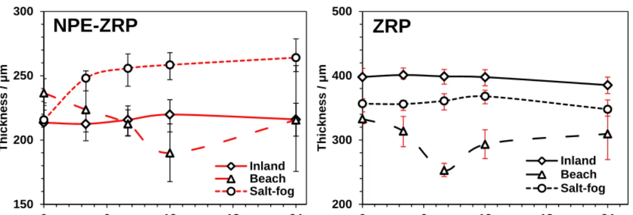
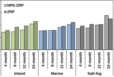
4.3.1.2 Coating Thickness ...83
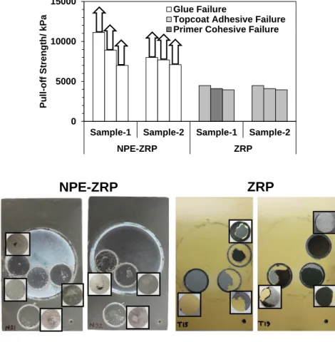
4.3.1.3 Pull-off Strength...84
4.3.1.4 Characterization of Zinc Consumption ...85
4.3.2 Water Immersion ...89
4.3.2.1 Electrochemical Analysis (OCP-LPR) ...90
4.3.2.2 Electrochemical Impedance Spectroscopy (EIS) ...92
4.3.2.2.1 NPE-ZRP ...92
4.3.2.2.2 ZRP ...100
4.3.2.3 Visual Observation...105
4.3.2.4 Coating Thickness ...106
4.3.2.5 Pull-off Strength Test ...107
4.3.2.6 Characterization of Zinc Consumption ...108
4.3.3 Electrochemical Polarization ...109
4.3.3.1 Visual Observation...109
4.3.3.3 Polarization Behavior...113
4.3.3.4 Disbondment Test ...120
4.3.3.5 Pull-off Strength Test ...123
4.3.3.6 Characterization of Zinc Consumption ...124
CHAPTER 5ROBUSTNESS OF NPE-ZRP COATING FOR REPAIR APPLICATION ...130
5.1 Introduction ...130
5.2 Steel Substrate Characterization before Coating Application ...131
5.3 NPE-ZRP Coating ...133
5.3.1 Material Characterization ...133
5.3.2 Results and Discussion ...138
5.3.2.1 Outdoor Exposure ...138
5.3.2.1.1 Visual ...138
5.3.2.1.2 Coating Thickness ...140
5.3.2.1.3 Pull-off Strength Test ...141
5.3.2.2 Cyclic Exposure ...142
5.3.2.2.1 Visual Observation ...142
5.3.2.2.2 Coating Thickness ...144
5.3.2.2.3 Pull-off Strength Test ...147
5.3.2.4 Electrochemical Analysis (OCP-LPR) ...147
5.3.2.5 Characterization of Zinc Consumption ...152
5.4 ZRP Coating ...159
5.4.1 Material Characterization ...159
5.4.2 Results and Discussion ...162
5.4.2.1 Outdoor Exposure ...162
5.4.2.1.1 Visual Observation ...162
5.4.2.1.2 Coating Thickness ...163
5.4.2.1.3 Pull-off Strength Test ...164
5.4.2.2 Cyclic Exposure ...165
5.4.2.2.1 Visual Observation ...165
5.4.2.2.2 Coating Thickness ...166
5.4.2.2.3 Pull-off Strength Test ...168
5.4.2.4 Electrochemical Analysis (OCP-LPR) ...169
5.4.2.5 Characterization of Zinc Consumption ...172
CHAPTER 6IMPROVEMENTS IN COATING DURABILITY BY NANO-PARTICLES ...177
6.1 Background ...177
6.2. Material Characterization ...180
6.3 Coating Durability by Surface Measurements ...183
6.3.1.1 Pull-off Strength ...183
6.3.1.2 Wetting Property ...188
6.3.2 Test Group B ...193
6.3.2.2 Wetting Property ...194
6.4 Statistical Approach to Find Coating Durability ...196
CHAPTER 7ZINC CONSUMPTION MECHANISM ...203
7.1 Introduction ...203
7.2 Role of Nano-Particles on Barrier and Cathodic Protection ...203
7.2 Role of Nano-Particles on Coating Bond Strength ...207
CHAPTER 8CONCLUSIONS ...212
RECOMMENDATIONS FOR FUTURE RESEARCH ...214
REFERENCES ...216
APPENDICES ……….……225
LIST OF TABLES
TABLE PAGE
Table 2.1. Corrosion Rates of Carbon Steel in Different Environmental Exposure ...12
Table 2.2. Formulation Related Failures (Bayer & Zamanzadeh, 2004) ...28
Table 2.3. Adhesion Related Failures (Bayer & Zamanzadeh, 2004) ...29
Table 2.4. Substrate Related Failures (Bayer & Zamanzadeh, 2004) ...29
Table 2.5. List of SSPC and NACE Standards Specifications for Surface Finish. ...33
Table 2.6. Electrode Potential of Metals in Seawater (Jones, 1996). ...49
Table 3.1. Chemical Composition of the Low Carbon Steel Panels. ...59
Table 3.2. Pre-coating Surface Preparation. ...70
Table 3.3. Alternate Wet/Dry Exposure Sequence (20 Cycles). ...73
Table 4.1. Characteristics of the Coatings under Study ...80
Table 4.2. Comparative Mass Loss After Exposure ...119
Table 4.3. Zinc Consumption Characterization of Both Coatings. ...128
Table 5.1. Zinc Consumption Characterization of NPE-ZRP Scribed Samples. ...156
Table 5.2. Zinc Consumption Characterization of ZRP Scribed Samples. ...175
Table 6.1. Characteristics of the Coatings under Study. ...182
LIST OF FIGURES
FIGURE PAGE
Figure 2.1. Metallographic Cross-section of Three-coat System. ...16
Figure 2.2. Metallographic Cross-section of Hot-dip Galvanizing (Sabbir, 2017). ...19
Figure 2.3. Thermal Spray Coating, Zinc on Steel (by Lau, K. & courtesy of FDOT). ....21
Figure 2.4. Location of Florida Steel Bridges. ...22
Figure 2.5. Age Distribution of Florida Steel Bridges. ...22
Figure 2.6. Age for Bridge Paint Repair (FDOT Bridge Inspection Report). ...23
Figure 2.7. Age Distribution of Repainted Bridges (FDOT Bridge Work Plan 08-18)...23
Figure 2.8. Bridge Condition State over Age (FDOT Bridge Inspection Report). ...24
Figure 2.9. Condition State over the Service Life (FDOT Bridge Inspection Report). ....25
Figure 2.10. Number of Repainted Bridges (FDOT Bridge Work Plan 08-18). ...26
Figure 2.11. Listed Repair Program for Year 2018 Bridge Work Plan. ...27
Figure 2.12. FDOT Cost Spent for Steel Bridge Repainting (Work Plan 08-18). ...27
Figure 2.13. Experimental Threshold Chloride Level Data (Fuente et. al., 2006). ...35
Figure 2.14. Environmental Classification of Structures (FDOT, 2017). ...38
Figure 2.15. Chloride Ion Deposition and Concentration, (NADP, 2015). ...39
Figure 2.16. Exposure Environment based on Chloride Exposure. ...39
Figure 2.17. Corrosion Rate with Distance from the Ocean (Morrison, 1980). ...40
Figure 2.18. Typical Painting Systems Used for Maintenance (TRS, 2014). ...41
Figure 2.19. Structure of Carbon Nano-particles (Zhang, el. Al., 2010). ...42
Figure 2.20. Nano-Particle Enriched Zinc-Rich Primer (NPE-ZRP) Coating. ...42
Figure 2.22. Equivalent Circuit of Coating in Contact with Electrolyte by Considering
the Base Property of the Steel. ...53
Figure 2.23. Idealized Impedance Diagram and Equivalent Circuit of Coated Metal System with Coating Defect. ...54
Figure 2.24.Energy Balance of a Liquid Drop Resting on a Solid Surface. ...56
Figure 3.1. Location of Outdoor Exposure Sites. ...61
Figure 3.2. Weather Data for Outdoor Test Sites. ...61
Figure 3.3. Test setup for Salt-fog Exposure. ...62
Figure 3.4. Test Cell Configuration. ...64
Figure 3.5. Laboratory Test Set-up for Potentiostatic Polarization. ...65
Figure 3.6. Sandblasting of the Coupons (Plain Steel Coupon). ...67
Figure 3.7. Surface Preparation by Grinding of Three-coat System. ...67
Figure 3.8. Hand Cleaned Steel Panels (Three-coat System). ...68
Figure 3.9. Measurement of the Chloride Contamination Level. ...69
Figure 3.10. Humidity Chamber for Test Panel Exposure...69
Figure 3.11. Sample Exposure after Repair. ...71
Figure 3.12. Outdoor Sample Exposure at FIU. ...72
Figure 3.13. Weather Data for FIU Test Site. ...72
Figure 3.14. Cyclic Wet/Dry Exposure in Three Different Condition (20 Cycles). ...73
Figure 3.15. Coating Separation Modality. ...75
Figure 4.1. Metallographic Cross-sections of Test Coatings. ...78
Figure 4.2. Zinc Particle Size Distribution in the Polymer Matrix. ...79
Figure 4.4. Visual Appearance of the Outdoors and Salt-fog Exposed Samples. ...82
Figure 4.5. Coating Thickness of Outdoor and Salt-fog Exposed Samples over Time. ....84
Figure 4.6. Pull-Off Strength of Outdoor & Salt-fog Exposed Samples. ...85
Figure 4.7. Degradation of the Outdoor and Salt-fog Exposed Unscribed Samples. ...86
Figure 4.8. Zinc Consumption of Outdoor & Salt-fog Exposed Unscribed Samples. ...87
Figure 4.9. Degradation of the Exposed Scribed Samples (24 months Exposure). ...88
Figure 4.10. Open Circuit Potential during the Exposure. ...91
Figure 4.11. Corrosion Current over Exposure Duration. ...91
Figure 4.12. EIS response of NPE-ZRP Unscribed sample (1MHz to 1Hz). ...93
Figure 4.13. EIS response of NPE-ZRP Unscribed sample (100 kHz to 1mHz)...94
Figure 4.14. Equivalent Circuit for EIS Analysis of NPE-ZRP Unscribed Sample. ...95
Figure 4.15. Equivalent Circuit Elements for NPE-ZRP Unscribed Samples. ...98
Figure 4.16. EIS response of NPE-ZRP Scribed sample (100 kHz to 1 mHz). ...99
Figure 4.17. EIS response of ZRP Unscribed sample (1MHz to 1Hz). ...102
Figure 4.18. EIS response of ZRP Unscribed sample (100 kHz to 1mHz). ...103
Figure 4.19. EIS response of ZRP Scribed sample (100 kHz to 1 mHz). ...104
Figure 4.20. Condition of the Water Immersed Samples...106
Figure 4.21. Change in Coating Thickness after Water Immersion. ...107
Figure 4.22. Pull-off Strength and Failure Modality of Samples after Immersion. ...108
Figure 4.23. Degradation of the Water Immersed Samples. ...108
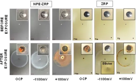
Figure 4.24. Condition of the Representative Samples before and after Exposure. ...110
Figure 4.25. OCP& LPR evolution of NPE-ZRP and ZRP with Time...112
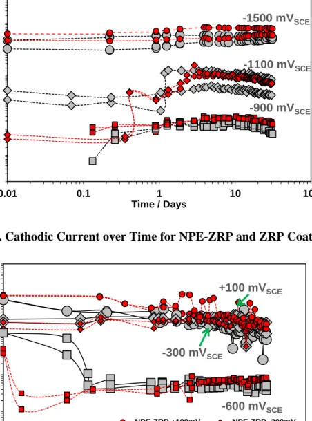
Figure 4.27. Cathodic Current over Time for NPE-ZRP and ZRP Coating. ...114
Figure 4.28. Anodic Current over Time for NPR-ZRP and ZRP Coating. ...114
Figure 4.29. Cumulative Cathodic Charge for NPE-ZRP and ZRP Coating. ...116
Figure 4.30. Cumulative Anodic Charge for NPE-ZRP and ZRP Coating. ...117
Figure 4.31. Steel Corrosion after Anodic Polarization (–300mVSCE). ...118
Figure 4.32. Disbondment of Samples after Exposure. ...121
Figure 4.33. Metallographic Cross-section of Exposed Samples to -1500mV. ...121
Figure 4.34. Metallographic Cross-section of Exposed Samples to -600mV. ...123
Figure 4.35. Pull-off Strength after Exposure to Various Polarization Regimes...124
Figure 4.36. X-Ray Diffractogram for the sample after exposure. ...125
Figure 4.37. Zinc Consumption along the 300 µm from Defect Site. ...126
Figure 4.38. Effective Zinc Consumption per Unit Thickness along the 5mm Length. ..126
Figure 4.39. Zinc Consumption Modality after Exposure. ...127
Figure 5.1. Condition of Uncoated Steel Test Panels after Exposure. ...131
Figure 5.2. X-Ray Diffractogram for the Steel Plate after exposure. ...133
Figure 5.3. Representative Surface Condition of Repaired Test Coupons. ...133
Figure 5.4. Micrographs of Repaired NPE-ZRP Samples with Sandblasted Steel. ...135
Figure 5.5. Micrographs of Repaired NPE-ZRP Samples with Handcleaned Steel. ...135
Figure 5.6. Coating Thickness of NPE-ZRP Coupons after Repair. ...136
Figure 5.7. Coating Pull-off Strength of NPE-ZRP Coupons after Repair. ...137
Figure 5.8. Different Failure Modality of Pull-Off Strength for NPE-ZRP Coupons. ....138
Figure 5.9. Condition of Sandblasted NPE-ZRP Samples after Outdoor Exposure. ...139
Figure 5.11. Coating Thickness of Outdoor Exposed NPE-ZRP Repaired Samples...141
Figure 5.12. Pull-off Strength of NPE-ZRP Samples after Outdoor Exposure. ...142
Figure 5.13. Condition of NPE-ZRP Scribed Samples after Cyclic Exposure. ...143
Figure 5.14. Condition of NPE-ZRP Unscribed Samples after Cyclic Exposure. ...144
Figure 5.15. Coating Thickness of NPE-ZRP Samples after Cyclic Exposure. ...145
Figure 5.16. Coating Thickness of NPE-ZRP Samples after Cyclic Exposure. ...146
Figure 5.17. Pull-off Strength of NPE-ZRP Coupons after Cyclic Exposure. ...147
Figure 5.18. OCP of Unscribed NPE-ZRP Samples during Cyclic Exposure. ...149
Figure 5.19. OCP of Scribed NPE-ZRP Samples during Cyclic Exposure. ...149
Figure 5.20. Icorr of Unscribed NPE-ZRP Samples during Cyclic Exposure. ...150
Figure 5.21. Icorr of Scribed NPE-ZRP Samples during Cyclic Exposure. ...152
Figure 5.22. X-sectional Micrograph of Sandblasted Unscribed NPE-ZRP Samples. ....153
Figure 5.23. Zinc Consumption of Sandblasted Unscribed NPE-ZRP samples. ...154
Figure 5.24. Micrograph of Handcleaned Unscribed NPE-ZRP Samples. ...155
Figure 5.25. Micrograph of Sandblasted Scribed NPE-ZRP Samples. ...157
Figure 5.26. Micrograph of Sandblasted Scribed NPE-ZRP Samples. ...158
Figure 5.27. Repaired Coupons after Application of ZRP Coating. ...159
Figure 5.28. Coating Thickness of ZRP Coupons after Repair. ...160
Figure 5.29. Optical Micrograph of ZRP Coating Repair Coupon. ...160
Figure 5.30. Coating Pull-off Strength of ZRP Coupons after Repair...161
Figure 5.31. Failure Modalities of Pull-off Strength Testing for ZRP Coupons. ...162
Figure 5.32. Condition of the Sandblasted ZRP Samples after Outdoor Exposure. ...163
Figure 5.34. Pull-off Strength of ZRP Coupons after Outdoor Exposure. ...165
Figure 5.35. Typical Condition of Scribed ZRP Samples after Cyclic Exposure...166
Figure 5.36. Typical Condition of Unscribed ZRP Samples after Cyclic Exposure. ...166
Figure 5.37. Coating Thickness of ZRP Coupons after Cyclic Exposure. ...167
Figure 5.38. Coating Thickness of ZRP Coupons after Cyclic Exposure. ...168
Figure 5.39. Pull-off Strength of ZRP Coupons after Cyclic Exposure. ...169
Figure 5.40. OCP of ZRP Samples during Cyclic Exposure. ...171
Figure 5.41. Icorr of ZRP Samples During Cyclic Exposure. ...171
Figure 5.42. Micrograph of Hand Cleaned Unscribed ZRP Samples. ...173
Figure 5.43. Zinc Consumption of Sandblasted Unscribed ZRP samples. ...174
Figure 5.44. Micrograph of Sandblasted Scribed ZRP Samples. ...175
Figure 6.1. Contact Angle of the Pre-exposed Steel Substrate. ...181
Figure 6.2. Optical Micrograph of NPE-ZRP Coating. ...182
Figure 6.3. (A) Osmotic Blister formation on the salt contaminated samples (B) Rust Development at the interface of Humidity exposed samples.. ...183
Figure 6.4. Different Failure Modality of Pull-off Strength. ...184
Figure 6.5. Coating Pull-off Strength of ZRP (Test Group A). ...185
Figure 6.6. Coating Pull-off Strength of NPE-ZRP (Test Group A). ...186
Figure 6.7 Liquid droplet on Test Group A Sample in As-received Condition. ...188
Figure 6.8. Percent Difference in Contact Angle for ZRP Samples (Test Group A). ...189
Figure 6.9. Percent Difference in Contact Angle of NPE-ZRP Samples (Group A). ...190
Figure 6.10. Correlation between Contact Angle and Pull-off Strength (Group A). ...191
Figure 6.12. Liquid droplet on Test Group B Sample after Exposure. ...195
Figure 7.1. OCP and Corrosion Current over Time. ...205
Figure 7.2. EDS Point Mapping on NPE-ZRP Sample. ...207
Figure 7.3. EDS Mapping of Salt-fog Exposed NPE-ZRP Unscribed sample (Top). ...208
Figure 7.4. EDS Mapping of Salt-fog Exposed NPE-ZRP Unscribed sample (Botm)....209
Figure 7.5. EDS Mapping of a Salt-fog Exposed ZRP Unscribed sample. ...210
Figure 7.6. EDS Mapping of a Solution Immersed NPE-ZRP Scribed sample. ...211
LIST OF SYMBOLS
Zn Zinc
Rs Solution resistance
Rpo Coating pore resistance
Cc Coating capacitance
Cdl Double layer capacitance
Rp Polarization resistance ε0 Vacuum permittivity εr Relative permittivity A Area d Coating thickness ρ Resistivity n Number of pores Z Total impedance ω Angular frequency Yo Pre-exponential term
Icorr Corrosion current
ABBREVIATIONS AND ACRONYMS
ATR Activated Titanium Rod
ASTM American Society for Testing and Materials
CPE Constant Phase Element
EDS Energy Dispersive Spectroscopy
EIS Electrochemical Impedance Spectroscopy
FHWA Federal Highway Association
HDG Hot-dip Galvanizing
LPR Linear Polarization Resistance
NACE National Association of Corrosion Engineers
NPE-ZRP Nano-Particle Enriched Zinc-Rich Primer
OCP Open Circuit Potential
SSPC Society for Protective Coatings
SEM Scanning Electron Microscopy
SCE Saturated Calomel Electrode
XRD X-ray Diffraction
CHAPTER 1 INTRODUCTION 1.1 Background
Corrosion is a major concern for the long-term durability and structural integrity of steel components of highway bridges. Approximately 15% of all bridges are
structurally deficient due to corrosion (Materials Performance, 2002). Out of the approximate 600,000 highway bridges in the United States, 200,000 are steel bridges. Damage to the steel bridge superstructure can be exacerbated when it is unprotected or inadequately protected from the environment. In particular, aggressive marine
environments that contain high concentrations of coastal airborne salt enhance corrosion. It was evident that corrosion of structural steel components was significant in the
catastrophic collapse of the Silver Bridge (Point Pleasant, WV) in 1967 (Biezma1 and Schanack, 2007), the Mianus River Bridge (Connecticut) in 1983(NTSB, 1983), Lowe’s Motor Speedway Bridge (North Carolina) in 2000 (Cederquist, 2000), Kinzua Bridge (Pennsylvania) in 2003 (Jeffery, 2009), and Leo Frigo Memorial Bridge (Wisconsin) in 2013 (Khalid et.al., 2018).
The application of protective coatings has been widely used for corrosion mitigation of atmospherically exposed structural steel. Different coating systems for corrosion protection of steel bridges have been developed and implemented over time due to the changes in environmental and health regulations, economics, and advances in technology. Even with the continuous development of coating technologies, coating systems are still susceptible to deterioration and thus unable to provide protection for the long-term design bridge service life. Periodic maintenance of coatings is required for
additional service life against exposure to its surrounding environment. Furthermore, maintenance including coating removal, containment, and application is costly. Of the estimated $8.3 billion annual costs of corrosion in highway bridges, $500 million is expended only for coating maintenance of highway steel bridges. So, effective and cost-efficient coating systems that meet or exceed health and environmental regulations are always of interest.
The majority of the steel bridges in the interstate highway system were
constructed between the 1950s and 1980s. Until the 1970s, bridges were generally coated by alkyd-based paint containing toxic lead and chromate (Kogler Jr. and Chong, 1997). Approximately 80 to 90 percent of the 200,000 steel bridges in the United States were coated with lead or other toxic heavy metal-based inhibitor coatings (Myers et al., 2010). These old technology coating systems usually consisted of several layers and required costly routine levels as well as major paint maintenance within eight to ten years of service life. Many of those coating systems became prohibited by Environmental
Protection Agency regulations due to environmental and health hazards. After the 1970s, an entirely different coating technology containing sacrificial zinc pigments was
introduced for bridge application; and at present, the zinc-rich primer based three-coat system is widely used in the United States. The metallic zinc pigments ideally would provide corrosion resistance by sacrificial protection. The three-coat system typically consists of either an organic or inorganic zinc-rich primer (although other primers have been formulated) followed by an epoxy midcoat and a topcoat. Generally, the
performance of zinc-rich paints outperformed the previous lead-based paints.
bridge. Furthermore, premature degradation may occur if there are flaws in the system due to improper application.
Repair of the degraded coating material should not be overly complicated and must be cost-effective. Appropriate surface preparation and identification of
environmental exposure parameters such as humidity, surface moisture, air-born salt contamination and their effects on coating physical properties and corrosion mitigation should be considered. It was reported that modern paint coatings may require early maintenance especially if exposed in aggressive environments (Florida Department of Transportation (FDOT) Bridge Work Plan, Personal Communication, June 21, 2018). The long-term effectiveness of coating systems is of major importance to reduce maintenance costs. The coating system not only should provide adequate corrosion control and meet environmental and health regulations, but also the coating durability should be attuned to expected bridge design life. The selection of compatible repair coating material and the corresponding level of surface preparation is the critical
parameter for proper protection from its exposure environment. In consideration of ease of coating application, application quality, costs, and durability in aggressive exposure conditions, new materials for corrosion mitigation are needed. Many coating systems have been introduced by the industry and government sectors for varying applications. These commercially-available materials may have a useful application for highway bridges. Novel coatings containing carbon nano-particles with the zinc-rich primer (NPE-ZRP) have garnered attention for possible highway bridge applications as promoted for providing better electrical continuity of the zinc pigment for enhanced cathodic
in aggressive environments relevant to highway bridges should be evaluated. Topics of importance include identifying appropriate surface preparation, application, compatibility and determining resiliency to environmental exposure conditions during and after repair. 1.2 Problem Statement and Research Objective
The need for effective corrosion mitigating coating systems with longer service life and reduced maintenance requirements are important to maintain the civil highway infrastructure in the U.S. Commercially available coating systems specified for bridge applications do not necessarily have service life commensurate with bridge service specification and require regular inspection and maintenance. Other limitations for available coating systems are application and repair susceptibilities. Therefore, there is continued interest to explore alternative novel coating systems that may have a suitable application for highway steel bridges. A nano-particle enriched zinc-rich primer (NPE-ZRP) based coating system was identified for study due to its possible beneficial characteristics. Application and exposure conditions of interest include coatings for structural steel. The first step to evaluate any material is to identify possible degradation modalities to assess the long-term exposure durability. In marine bridge, structural steel application, important environmental and exposure conditions include alternate wet/dry cycle, moisture availability, temperature, humidity, salt exposure, ultraviolet exposure, pH, crevice environment and localized coating defects. The environmental and exposure conditions, as well as modality and severity of initial coating defects, can all contribute to the degradation of the coating and its efficacy as a corrosion mitigation system.
Preventative regular bridge maintenance reduces the risk of catastrophic failure and can be beneficial for the economy by providing extended service life. For steel bridge, paint
maintenance selection of compatible repair material and appropriate application is crucial for corrosion durability. Like a new coating application, harsh environmental exposure and contaminants during as well as after the coating application may also be detrimental for repair coating durability. The application of the repair coating should not be overly complicated or time-consuming. Minimizing the impact on transportation is important. Outdoor and lab testing was intended to elucidate coating degradation. The research goals include identifying and predicting coating durability and the ability to mitigate corrosion. So, the objective of this study was to identify the corrosion mitigation and degradation mechanism of NPE-ZRP coating system, also the robustness of the coating system to use for repair application in marine exposure relevant to highway bridge structural steel elements.
Hypothesis
Zinc-rich primer-based coating system containing carbon nano-particles will provide improved coating durability for marine steel bridge applications by providing enhanced mechanical (cohesion and adhesion) and corrosion protection properties. The nano-particles will provide extended galvanic coupling of the sacrificial zinc pigments with the exposed steel substrate and thus extend the life of the steel structure. Coating application in adverse environmental conditions will not cause an additional detrimental effect on durability due to the presence of carbon nano-particles.
Research Objectives and Questions
The objective of the work presented here was to verify that if NPE-ZRP coating can provide enhanced coupling of the zinc pigments with the steel substrate. Testing included evaluation in extended outdoor atmospheric and salt-fog exposures. Since
moisture and salt were expected to be major factors in marine atmospheric exposure, a set of testing was made by immersing coated steel samples in 3.5wt% NaCl solution. Testing here considered localized coating damage that exposed the steel substrate. Furthermore, it was of interest to identify the influence of nano-particles polarization behavior of embedded zinc pigments. Test conditions to promote the electrochemical activity of the zinc (including both oxidation and reduction reactions) included various levels of electrochemical polarization. In order to assess the effect of nano-particles on zinc electrochemical coupling and steel corrosion development, the extent of zinc consumption as well as coating degradation was addressed. A traditional zinc-rich primer (ZRP) was studied to reference the performance of NPE-ZRP. To meet the research objectives the following questions needed to be addressed:
1. How does the nano-particle enhance the coating durability?
• Discriminate extrinsic parameters (such as coating thickness, zinc pigment distribution, etc) of a commercially available ZRP and NPE-ZRP coating that can affect coating durability.
• Determine the extent of corrosion mitigation afforded by NPE-ZRP compared to conventional ZRP in different environments containing variable moisture and salt content.
• Identify if nano-particle presence can promote effective galvanic coupling of the reaction sites away from the defect. Identify if beneficial cathodic polarization can promote extended zinc anodes with time. Identify if promoted galvanic coupling can reassure extended cathode.
• Identify mitigation of mechanical coating degradation (such as adhesion loss, disbondment and anodic blistering) afforded by the enhanced tensile property of NPE-ZRP coating.
• Identify an approach to estimate the long-term performance of NPE-ZRP coating. 2. What are the negative effects of adverse surface conditions on NPE-ZRP coating
durability?
• Determine the effects of surface contamination on undercoating adhesion, electrical continuity of the pigments to the steel and corrosion development.
• Determine coating integrity in aggressive exposure conditions.
3. What are the effects of adverse environmental exposure on NPE-ZRP coating durability for repair applications?
• Determine the effects of inappropriate surface preparation and adverse
contaminants on undercoating adhesion, electrical continuity of the pigments to the steel and corrosion development.
• Determine the effects of adverse environmental exposure on the integrity of repair coating durability.
4. What is the influence of nano-particles on the major interdependent coating parameters related to coating durability?
• Develop a statistical model that can correlate the coating parameters with coating durability.
1.3 Research Approach
The proposed research approach includes:
1. Characterize physical, metallurgical, and other material traits of a NPE-ZRP (commercially available) as well as a conventional ZRP coating system used in current practice. Identify the modality of coating defects formed during application as well as coating resilience to surface damage.
2. Expose coated samples with and without intentional defects to outdoor exposure (at beach site and inland locations), in laboratory exposure with aqueous solutions representative of pooled runoff water and aggressive salt-fog environments to assess the coating integrity for long-term corrosion durability.
3. Exposure to different levels of polarization with time, to identify the effect of electrochemical interaction of zinc pigments with steel defects to mitigate corrosion with the presence of nano-particles.
4. Assess corrosion development and efficacy of nano-particle presence on efficient galvanic protection by applied electrochemical measurements (OCP, LPR, EIS, and potentiostatic polarization).
5. Test sample preparations with conditions representative of conventional repair application.
6. After diverse surface preparation and adverse environmental pre-coating exposure, expose coated samples with and without intentional defects to aggressive
accelerated cyclic testing (include immersion in aqueous solution with Cl-, dry exposure in low humidity and aggressive salt-fog exposure) to identify the effect of alternate wet and dry exposure on coating robustness to repair susceptibility.
7. Material evaluation techniques such as visual, physical (thickness, pull-off strength), metallurgical assessment (optical and electron microscopy, Image Processing, EDS and XRD), to elucidate the findings from entire test exposure. 8. Develop a statistical model by correlating the coating durability parameters to
identify the influence of nano-particles. 1.4 Organization of the Dissertation
This dissertation is organized as follows:
Chapter 2 represents the present state of knowledge on the current highway steel
bridge protection practice through the application of the protective coating and general overview of the basic concept of electrochemistry related to coating evaluation.
Chapter 3 represents the methodology to achieve the objective of the research.
The detail test procedures and evaluation technique of the test samples are documented in this chapter.
Chapter 4 presents the results of the tested samples for the application of
NPE-ZRP coating for new structural steel, which was exposed to different test exposure. Associated discussion is made based on the test results to describe the degradation process related to that environment.
Chapter 5 presents the results of the tested samples for the application of
NPE-ZRP coating for repair application, which incorporated deficient surface preparation and were exposed to different test exposure. Associated discussion is made based on the test results to describe the degradation process related to that environment.
Chapter 6 presents the assessment of the effect of carbon nano-particles on the
performance of the NPE-ZRP coating system is explored by surface measurements and statistical model.
Chapter 7 summarizes the findings from the outdoor, accelerated salt-fog and
electrochemical tests that demonstrate the role of nano-particles on the zinc consumption mechanism of NPE-ZRP coating system.
Chapter 8 summarizes the conclusion about the NPE-ZRP coating durability in
exposure related to aggressive marine bridge environment and future recommendation. Some content in this dissertation has been published in report form to the sponsoring agency (Saiada, Sabbir and Lau, 2019) and published in conference proceedings (Saiada et al, 2017-19). Those published contents have been in part reproduced here.
CHAPTER 2 LITERATURE REVIEW 2.1 Steel Bridges and Service Environment
In the US, there are approximately 200,000 highway steel bridges. These bridges are located over a variety of exposure environments in terms of temperature, humidity, rainfall, ultraviolet radiation from the sun, pollutants, and airborne salts. Generally, the bridge environment is classified based on the potential threats from its surroundings as,
• Mild (rural): Little to no exposure to natural airborne or deicing salts, industrial pollutants, low humidity, and rainfall, usually located in an inland location.
• Moderate (industrial): Exposed to some or occasional airborne or deicing salt runoff, corrosive industrial contaminants, moderate to high humidity, usually located in a heavily polluted urban area.
• Severe (marine): Exposure to high airborne salt or deicing salt, high humidity and moisture, usually located in proximity to the coastal area.
Table 2.1 shows the rate of carbon steel corrosion with exposure variation. The durability of any corrosion protection system for structural steel vastly depends on its surrounding environments. So proper corrosion protection technologies based on the surrounding exposure environment are required for the long-term durability of the structural systems.
Table 2.1. Corrosion Rates of Carbon Steel in Different Environmental Exposure (American Galvanizers Association, 2019).
Atmosphere Corrosion Rate (µm/year)
Rural 4 - 60
Urban 30 - 70
Industrial 40 - 160
Marine 60 - 170
2.2 Coatings for Corrosion of Steel Bridges
Coatings are the most widely used technology to protect steel infrastructure against its service environment and have been developed over the years to extend the life of the structure by improving the corrosion resistance. Protective coating systems are generally divided into three broad categories based on their mechanisms: barrier formed between the substrate and environments, inhibition of the corrosion processes, and coating acting as sacrificial materials. Barrier protection is the mode of protection provided by intact coatings whereas the other two modes are designated as active protection of damaged areas by coating components (Bierwagen, 1996).
2.2.1 Barrier Coating
A barrier coating creates an insulating and physical barrier, thus reducing the passage of corrosive elements and the availability of moisture through the coating layer to the substrate. The effectiveness provided by a barrier coating system highly depends on its permeability as well as coating thickness and binder type (Sørensen et al., 2009). The low conductivity of the electrolyte at the metal coating interface minimizes the transport of corrosion current between the anode and cathode, (Hare, 1989). The
properties of the coating/metal substrate interface are closely tied to the barrier properties of the system as failure was reported due to lack of adhesion (Bierwagen, 1996).
2.2.2 Inhibitive Coating
Inhibitive coating develops a passivation layer by the reaction of inhibitive pigments with the steel substrate in presence of moisture, which prevents access of the corrosive substance to the substrate (Amo et al., 2002). The efficiency of the inhibitive coating depends on the balance between the barrier properties of the coating and the degree of permeability to permit the diffusion of water to activate the pigments (Liu, 1998). The inhibitive pigments are generally water-soluble inorganic salts which facilitate their transportation to the defect site (Sørensen et al., 2009). The associated problem is that if the solubility is too high, blistering can form (Prosek and Thierry, 2004).
2.2.3 Sacrificial Coating
Sacrificial coatings are developed based on the principle of galvanic corrosion. The substrate is protected by a metal or alloy that is electrochemically more active than the material to be protected. A more active metal than steel becomes an anode when in direct contact with the less active steel substrate and eventually protect the steel substrate from corrosion. Sacrificial coatings are applied as primers. The effectiveness of the coating depends on the electrical contact of the substrate with the sacrificial metal as well as on the transfer of the galvanic current (Sørensen et al., 2009). Thus, sacrificial coatings should be highly pigmented to ensure proper metallic contact between the individual particles of the sacrificial metal. Coatings systems can also exhibit multiple corrosion mitigation characteristics. For example, HDG and Metalizing is a barrier but can have
sacrificial properties depending on environmental conditions. The zinc-rich primer system serves as a sacrificial coating but has barrier characteristics also (FHWA publication 1995).
2.3 Present Practice of Bridge Coating System
Prior to 1965, bridge coatings were generally oil-based multi-layers (5-6) coating systems containing lead/ chromium pigments as corrosion inhibitors. These coating systems were usually applied directly to the steel substrate after power tool cleaning (SSPC-SP3) covered with mill scale. Some level of maintenance was required typically within eight to ten years of application and another coating layer was added as repair policy (FDOTBridge Work Plan, Personal Communication, June 21, 2018). As a result, several layers were added on with time and subsequently adhesive failures were reported between the coating layers and from the steel substrate even sometimes because of the weight of the paint layers. Environmental regulations and advancement in paint chemistry have driven continuous changes in paint formulation. With the development of abrasive blasting technology to remove mill scale that provides a clean surface for paint
application, the coating industry shifted from several layered lead-alkyd paint systems to a new generation high performing zinc enriched coating system that provides galvanic protection. With the modern development and advancement in technology, the coating lifetimes to first major maintenance have gradually increased from 12 and 15 years to 20 and 25 years (NPL Corrosion Guide, 2015). Some coating systems that are currently used are described next.
2.3.1 Paint Coating System (Zinc-Rich Three-coat system)
bridges. Previous multi-coat systems have been replaced mostly by three-coat systems, and research is still going on to improve its performance.
The majority of state highway departments specified the zinc-rich three-coat systems as a conventional coating system for highway steel bridges due to numerous technical, political, and economic issues (FHWA publication 2015). The protection mechanism of the zinc-rich primer (ZRP) coating system is based on the galvanic coupling of the zinc pigments referred to as cathodic protection as well as barrier protection of the coating layers. The galvanic feature differentiates ZRP from traditional barrier coatings. Zinc-rich primers are usually inorganic zinc (IOZ) or organic zinc (OZ). IOZ primers consist of zinc metal pigment mixed into an inorganic silicate-based paint binder. This binder can be either solvent-borne (ethyl silicate) or waterborne (alkali silicate). OZ primers contain zinc metal pigment mixed into an organic paint resin such as epoxy or urethane. The current “gold standard” for steel bridge coating practice involves the use of a three-coat system consisting of an inorganic zinc-rich primer, an epoxy midcoat, and a urethane topcoat (Figure 2.1). The different layers of three-coat systems have specific functions. The primer provides sacrificial protection and the midcoat (usually epoxy binders) acts as an additional barrier to the ingress of aggressive environment agents (moisture and chemicals) toward the steel/coating interface. Corrosive agents are transported to the primer/midcoat interface by diffusion through the above layers (Kolek, 1997). Usually, three types of epoxy coatings are used as an intermediate layer such as epoxy ester, epoxy lacquer, and a two-component epoxy. Epoxy ester is a vegetable oil-modified resin which is alkali resistance and epoxy lacquer consists of high molecular weight that needs short curing time. Two-component epoxies
are polyamides, comprises of greater flexibility and longer pot life (Chang and Chung, 1999). Usually, these epoxy intermediate layers provide excellent resistance to corrosive agents. Topcoats are used to retain coating aesthetics and to provide wear & tear as well as UV resistance. Typically, urethane and polyurethane binders are used as oil-modified urethane, moisture-cured urethane, and two-component urethane. Oil modified pigmented urethanes are not appropriate for steel infrastructure due to a lack of durability. Moisture cured urethane use the ambient moisture for curing and pigmentation is not suitable due to moisture susceptibility thus only used as a clear finish. Two-component urethane use polyols, polyethers, polyesters or acrylics with urethane to produce a resistant and durable coating. For three-coat systems, hydroxylated acrylic or hydroxylated polyester binded urethanes are the most commonly used topcoat due to their superior UV resistance and faster drying capacity (Chang et al., 1999).
Figure 2.1. Metallographic Cross-section of Three-coat System. ZRP ideally prevents corrosion of the steel at small coating damage sites and coating film holidays by sacrificing the zinc pigments well known as cathodic protection. Proper galvanic action depends on the chemical nature of the binder, amount of metallic zinc known as pigment volume concentration, the grain size of the zinc pigments, zinc to-steel area ratio and the coating film thickness (Hammouda et al., 2011). The electrical
200 µm
Polyurethane Epoxy
Zinc Pigm ent
continuity between the zinc pigments and the steel substrate is the crucial parameter for the effectiveness of zinc pigments to provide efficient galvanic protection (Abreu et al., 1999). For efficient electrical continuity, the pigment volume concentration (PVC) of the zinc pigments in the coating should exceed the critical PVC. It has been reported that the quantity of zinc pigments (even with content as high as 80-90% wt) alone cannot ensure effective electrical continuity to provide long-term galvanic protection (Shreepathi, et. Al., 2010). Studies also have found that zinc particle shape is also critical for continuity and spherical pigments cannot provide efficient electrical contact (Schaefer and Miszczyk, 2013). Furthermore, coatings with high pigment content can be brittle as well as porous and exhibit poor substrate and/or inter-coat adhesion. It also may create difficulties in application due to high viscosity and poor dispersion (Park and Shon, 2014). After the consumption of connected zinc pigments, the long-term protection can also be in part due to the barrier protection provided by the zinc oxidation products. The barrier mechanism develops from the blockage of inherent coating pores by zinc corrosion products. The formation of zinc oxidation product blocks the coating porosity and leads to a highly compact structure that can hinder the ingress of adverse corrosive agents to the steel substrate. But the zinc consumption for cathodic protection can also affect electrical continuity by creating hindrance to electron flow. Thus, electrical continuity and coating porosity, define the anticorrosive properties of ZRP.
The corrosion protection of the three-coat system with inorganic zinc primers was reported to be better for new construction than with organic zinc primers. However, the sensitivity of inorganic zinc primers to surface conditions limits its application to controlled settings in the shop. Research on three-coat systems by the Michigan
Department of Transportation concluded good early performance to protect the steel from corrosion after five years (Phifer, 1993). The Wind Gap Bridge near Pittsburgh, the Martin Luther King Bridge in Richmond and MoDOT bridge A2107 in Franklin are some examples of bridges coated with inorganic zinc-rich primer with records of long-term durability. When the bridges were evaluated after ~20 years, the coating was found to be in excellent condition with only a few areas with slight coating degradation in need of touch-up attention (Kline, 2009). FHWA initiated a research program in August 2009 to identify coating systems that can provide long-term durability with minimal maintenance. Eight selected coating systems with a promising performance in part based on prior experimental data from accelerated laboratory testing and outdoor exposure testing were evaluated (Kodumuri & Lee, 2012). The evaluation consisted of accelerated laboratory testing (consisting of cyclic environmental exposure to temperature, UV, and moisture, and salt) and outdoor marine and simulated salt exposure environments. The study concluded that the three-coat systems with zinc-rich epoxy and polyurethane topcoats performed well but none of the coating systems can meet long-term maintenance-free coating applications.
2.3.2 Hot-dip Galvanizing
Hot-dip galvanizing (HDG) is a method of applying metallic coatings to structural steel and has been used to coat bridge components for many years (Zhmurkin, 2009). Hot-dip galvanizing involves immersing the steel components in a bath of molten zinc. The immersed surface form an integral bond by developing a thick zinc-iron alloy
coating with different alloy composition (Figure 2.2) defined as Gamma, Delta, Zeta, and Eta layer (American Galvanizers Association, 2017). The thickness of the galvanized
coating is influenced by the size and thickness of the workpiece, the steel surface preparation, and the chemical composition of the steel. The galvanized coating protects the steel by providing an impervious barrier that does not allow moisture to contact the steel. This barrier layer develops by forming zinc corrosion products when exposed to the atmosphere. To prolong the service life of galvanized surface an additional barrier layer of zinc coating can be introduced as a duplex system (American Galvanizers Association, 2012). The combination of galvanized steel and painting can provide enhanced corrosion protection, but paint delamination due to weak bonding between paint and the metallic substrate can reduce the durability of duplex systems (Cabanelas, et. al.2007).
Figure 2.2. Metallographic Cross-section of Hot-dip Galvanizing (Sabbir, 2017). Many transportation departments have adopted hot-dip galvanizing due to its performance but transportation costs, as well as galvanizing kettle size and availability, have been an important factor (FHWA Publication, 2015). The formation of the alloyed layer depends on the steel chemistry and the processing condition. All the layers may not be formed depending on these conditions (Yeomans, 2004). Furthermore, hydrogen embrittlement due to the accommodation of hydrogen at the time of surface cleaning prior to HDG is another negative aspect. According to the American Galvanizing
50 µm
γ
δ
ζ
η
η ζ δ γ 500 µmAssociation, hot-dipped galvanized items will last 75 to 100 years in an aggressive marine environment (American Galvanizers Association, 2012). However,
documentation of early age peeling or delaminating of galvanizing and rusting of steel substrate has been made (Helsel, 2015).
2.3.3 Metallizing
Metallizing consists of the thermal spraying of zinc (Figure 2.3), aluminum or zinc-aluminum alloy directly onto steel surfaces (Bernecki et al., 1997, Koger et al., 1998 & Chang et al., 1999). The molten metals as a wire or in powder form are applied using an airstream spray onto the steel surface in a thin film. Metallizing can be applied in the shop or in the field with a specialized instrument. The steel surface is prepared by grit blistering or chemical etching for proper mechanical bonding. Aluminum requires more surface roughness than zinc (Chang and Georgy, 1999). Surface preparation
specifications include SSPC-SP 5/ NACE-1 (White metal blast cleaning), SSPC-SP 10 / NACE-2 Near white metal blast cleaning, (Chang and Georgy, 1999). Metalized coatings shield the steel surface by both sacrificial and barrier protection. The coating provides barrier protection, especially when applied along with a topcoat, whereas zinc or aluminum in the coating protects the steel at the location of any damage (Kogler Jr. and Chong, 1997). Sealers such as acrylic urethane, polyester urethanes, vinyls, phenolics, epoxy or thermal sprayed polymer can be used to enhance service life by sealing the pores in the coating (Chang and Georgy, 1999).
Figure 2.3. Thermal Spray Coating (Figure by Lau & courtesy of FDOT).
The cost of metalizing is high compared to traditional paint systems, but many transportation departments have adopted metallization due to its performance. Thermal spray coatings are susceptible to degradation on substrates with poor surface preparation (Chang and Georgy, 1999) which may limit their efficiency for field application.
Localized corrosion was observed in the early age of metalized coating of a bridge in Connecticut due to improper surface preparation.
2.4 FDOT Steel Bridge Performance 2.4.1 Steel Bridges of Florida
The FDOT bridge inventory includes 1,206 steel bridges (Data provided by FDOT). These bridges are located in varying service environments. In Florida, 94 steel bridges are located in coastal regions, 627 bridges are located over inland locations and the remaining 468 bridges are located over the water body (Figure 2.4). A significant number of these bridges are located in major population centers supporting vital
transportation infrastructure especially in coastal regions and most of the coastal bridges are movable bascule bridges. FDOT owns a large population of the movable bridges in the U.S. (Catbas, 2013). Figure 2.5 shows the age distribution of ~1200 of those Florida steel bridges. It is evident that the bridge inventory has mostly bridges with relatively
Steel Substrate
short service times. Sixty percent of the steel bridges are under 30 years and 40% of them are under 20 years of service life.
Figure 2.4. Location of Florida Steel Bridges.
Figure 2.5. Age Distribution of Florida Steel Bridges. 2.4.2 FDOT Bridge Coating Performance
Florida started using the three-coat paint system for new structural steel in the 1980s with a projected service life of more than 30 years. The coating systems of old bridges were also replaced by the three-coat system due to environmental regulation and advancement in coating technology. Records from inspections of painted steel bridges (Data provided by FDOT) in FDOT Districts indicated that it is possible early
0 0.2 0.4 0.6 0.8 1 0 20 40 60 80 100 120 C u m u la ti v e F ra c ti o n
Bridge Age (Years)
0 100 200 300 400 N u m b e r o f B ri d g e s
deterioration of the coating system within ~15 years. Although no severe coating deterioration was observed up to ~15 years, the indication of degradation of coating elements would suggest that the onset of damage may occur in the near future. FDOT bridge work plan (Data provided by FDOT) details and inspection records are provided below.
Inspections reported that there is a possible early coating degradation within ~15 years after the initial application (Data provided by FDOT). Usually, spot or zone repair recommended to stop further degradation. Within a short period of time, the repair started deteriorating again and gets worse with environmental exposure. The average year for the repainting of the steel bridges is around 25 years after the paint application (Figure 2.6).
Figure 2.6. Age for Bridge Paint Repair (FDOT Bridge Inspection Report).
Figure 2.7. Age Distribution of Repainted Bridges (FDOT Bridge Work Plan 08-18). 0 8 16 24 32 40
Bridge 1 Bridge 2 Bridge 3 Bridge 4
B ri d g e A g e ( Y e a rs
) Spot PaintingRepainting
0 0.2 0.4 0.6 0.8 1 0 50 100 C u m u la ti v e F ra c ti o n
Figure 2.7 shows the age distribution of ~500 steel bridges from the Bridge Work Plan 2008-2018. It is evident that more 50% of the repainted bridges were less than 20 years of service life. The bridges over 30 years of service life (> 35% of the repainted bridges) can have multiple paint repair as there was no detail information available about the paint system in the survey report.
Figure 2.8. Bridge Condition State over Age (FDOT Bridge Inspection Report). Figure 2.8 shows the condition state of different bridges over the service life. As can be seen, bridge coating started to deteriorate and changed from condition state 2 to1, typically after 14 years. Severe coating degradation (condition state 3/4) was observed after service of 22 years. Figure 2.9 illustrates the length of bridge condition state over the service life of four different bridges located over inland and water body. The typical recommendation for spot painting was reported at the age of ~15 years. After initial spot-painting, a full repair was recommended when a significant portion of the bridge turned to condition state 2/3 typically at the age of ~25years.
0 1 2 3 4 5 0 10 20 30 40 C o n d it io n S ta te o f th e B ri d g e
Figure 2.9. Condition State over the Service Life (FDOT Bridge Inspection Report). C S 1 C S 1 C S 1 C S 2 C S 2 C S 2 C S 2 CS2 CS2 CS2 CS4 CS4 CS4 9600 9650 9700 9750 9800 10 12 14 16 18 20 22 24 26 28 30 L e n g th (ft) Bridge 1 R e p a in t 9724 ft S po t P a int 2 3 f t R e pa int 7 5 f t S po t P a int 2 3 f t C S 1 C S 1 C S 1 C S 1 C S 1 C S 1 C S 1 C S 1 C S 1 CS2 CS2 CS2 CS3 CS3 CS3 5000 7500 10000 12500 15000 17500 10 12 14 16 18 20 22 24 26 28 30 L e n g th (ft)
Bridge Age (Years) Bridge 2 R e pa int 13615 ft C S 1 C S 1 C S 1 C S 1 C S 1 C S 2 C S 2 C S 2 C S 1 C S 2 C S 2 CS2 10000 12000 14000 16000 18000 20000 10 12 14 16 18 20 22 24 26 28 30 L e n g th (ft)
Bridge Age (Years) Bridge 3 R e pa int 17507 ft C S 1 C S 1 C S 1 C S 1 C S 1 CS 2 C S 2 C S 2 C S 1 C S 2 1000 1300 1600 1900 2200 2500 10 12 14 16 18 20 22 24 26 28 30 L e n g th (f t)
Bridge Age (Years)
Bridge 4 S po t P a int 9 4 2 ft R e pa int 1985 ft
2.4.3 FDOT Bridge Coating Maintenance Cost
Most of the Florida steel bridges contain ZRP coating systems as they are newly constructed or having paint replacement from previous lead and chromate-based paint systems. Field performance history showed that the steel bridges often require repaint long before their expected service life period. According to FDOT Bridge Work Plan reports from 2008 to 2018 (Data provided by FDOT), the replacement of steel bridge paint systems typically consists of a significant part of the total repair plan (Figure 2.10). For each of these years, the replacement of the bridge coating system was the highest number of individual repair work, as shown in Figure 2.11. Furthermore, as shown in Figure 2.12, a general growing trend in the amount of paint system replacements is observed. The cost of the associated maintenance requirements for paint coating systems is shown in Figure 2.12 and the annual costs typically exceed $25 million (Pouliotte 2012, Clarke 2016).
Figure 2.10. The number of Repainted Bridges (FDOT Bridge Work Plan 08-18).
0 150 300 450 600 N u m b e r o f R e p a ir W o rk Fiscal Year