Title
Friction-stir welding of ultrafine grained austenitic 304L
stainless steel produced by martensitic thermomechanical
processing
Author(s)
Sabooni, S; Karimzadeh, F; Enayati, MH; Ngan, AHW
Citation
Materials & Design, 2015, v. 76, p. 130-140
Issued Date
2015
URL
http://hdl.handle.net/10722/211564
Friction-stir welding of ultrafine grained austenitic 304L stainless steel produced by martensitic thermomechanical processing
S.Saboonia*, F.Karimzadeha, M.H.Enayatia, A.H.W.Nganb
aDepartment of Materials Engineering, Isfahan University of Technology, 84156-83111, Isfahan, Iran
bDepartment of Mechanical Engineering, The University of Hong Kong, Pokfulam Road, Hong Kong, China
Tel: +98 3133915744
Fax: +98 3133912752
Abstract:
An ultrafine grained 304L austenitic stainless steel was produced by martensitic thermomechanical processing and joined by applying friction stir welding (FSW). The martensitic thermomechanical processing comprised a cold roll procedure up to 80% reduction followed by annealing. After FSW, different grain structures in different regions of the weld nugget were observed due to the asymmetry in the heat generation during the welding process. Grain growth and dynamic recovery were found to be the most predominant phenomena in the region just ahead of the rotating tool during the thermal cycle of FSW. A banded structure was observed in the advancing side of the weld nugget. TEM observations revealed that nanometric sigma phase precipitates were present both in the grain boundaries and inside the grains of this region. Shear textures were clearly identified in the weld center. The lack of rotated cube texture in the ODF sections shows that the discontinuous dynamic recrystallization (DDRX) is not active in the final microstructure. Increasing the welding speed can reduce the final grain size of the weld nugget leading to higher hardness. Hardness is found to increase in the weld nugget and this is not just a grain refinement effect, but also due to the presence of sub-boundaries and a high density of dislocations.
Keywords: Austenitic stainless steel, Ultrafine grain, Friction stir welding, Recrystallization mechanism , EBSD, Sigma phase precipitation
1. introduction
Austenitic stainless steels are the most popular type of stainless steels with wide applications in different industries, from low-end to advanced applications like aerospace vehicles [1]. Although austenitic stainless steels possess high corrosion resistance, good formability and suitable welding properties, their relatively low hardness and yield strength have limited their wider applications [2-4]. Improving the mechanical properties of austenitic stainless steels have therefore become a critical concern, and advanced thermomechanical processing based on hot deformation or cold rolling-annealing is one of the most industrially applicable methods to produce nano- or ultrafine grained (UFG) austenitic stainless steels [5], which were found to exhibit high strength and ductility [2-4].
Most of the published research on UFG austenitic stainless steels to-date has focused on their production and mechanical property characterization. Weldability, as one of the most important factors of a material for being applicable, has not been systematically investigated. In the case of fusion welding of UFG materials, considerable grain growth in the heat affected zone, and the coarse cast structure in the weld zone, are two significant phenomena that can jeopardize the mechanical properties of the welded material relative to the UFG base material [6]. Monte Carlo simulations have shown that the average grain size of the heat affected zone in a fusion weld of a 2 μm grain size steel can increase up to around 120-150 μm under high heat input conditions [7]. Some methods have been proposed to alleviate the weld quality problems associated with coarsening of microstructures, including heat input control in traditional welding techniques [7,8], the use of high-energy fusion welding processes such as laser welding [7], and the use of coolants such as liquid nitrogen behind the welding zone [9], but despite these, deterioration of mechanical properties in the weld zone is still common. Recently, solid-state
welding processes like friction-stir welding have been successfully applied to join advanced materials [10-11]. Friction stir welding is a solid-state, hot-shear joining process in which a rotating tool penetrates in the material and the high heat caused by friction leads to material flow. FSW has been successfully applied to aluminum as well as magnesium alloys [12-14], but in comparison with these light alloys, limited research has been performed to study its applicability in high-temperature alloys such as steels, possibly due to the lack of suitable tools found for the FSW of such alloys [15]. According to the authors’ knowledge, there has not been any published record on FSW of UFG stainless steels and their microstructural evaluation during the welding process. Therefore, the aim of this paper is to produce a UFG 304L stainless steel and to study its microstructural changes during FSW.
2. Materials and Methods
A commercial AISI 304L stainless steel, in the form of a sheet with thickness 10 mm, was used as the initial material. Table 1 shows the chemical composition, and Fig. 1 shows the electron backscattered diffraction (EBSD) map, of the as-received material. The microstructure is equiaxed with an average austenite grain size of ~30 µm. The black, green and red lines in Fig. 1 represent high-angle grain boundaries (HAB) with misorientations larger than 150, Σ3 twin
boundaries and low-angle boundaries (LAB) with misorientations between 2º and 15º, respectively, and it can be seen that the microstructure contains large fractions of HAB and Σ3 twin boundaries, and just a small fraction of LAB. A small amount of elongated delta ferrite is also observed as indicated by blue color in the microstructure.
element C Cr Ni Mo Mn Si P S Co Cu V Fe Wt.% 0.026 18.35 8.01 0.15 1.24 0.323 0.024 0.005 0.129 0.24 0.1 Remain
Fig 1: Grain boundary map from EBSD of the as-received 304L stainless steel
Specimens with dimensions 100 mm × 40 mm were cut from the as-received material and cold rolled in a solution of ice and ethanol at -15 ºC up to 80 % reduction, to enable the initial coarse-grained austenite to transform into fine structured martensite. The cold rolled
samples were then annealed at 700 ºC for 300 min to obtain a UFG microstructure of austenite, through the reverse martensite-to-austenite transformation.
Friction stir welding was performed on the resultant UFG 304L using a vertical milling machine. The welding tool was made of tungsten carbide with a shoulder diameter of 16 mm. A conical pin with upper and lower diameters of 5.5 and 5 mm, respectively, and length of 1.8 mm, was used (Fig. 2(a)) . The sample plates were fixed onto a steel backing plate using a fixture to prevent any displacement during welding. For all tests, the tilt angle of the tool from normal direction was selected as 30. Argon gas shielding was introduced around the tool at a flow rate of
10 L/min to prevent excessive oxidation during the welding process. Welding trials were performed at a constant rotational speed of 630 rpm and different welding speeds from 20 to 160 mm/min. Fig. 2(b) shows schematic illustration of different regions on the welded sample.
Fig. 2: (a) Schematic illustration of the tool used in the friction stir welding experiments. Q1, Q2
and Q3 are heat generated at different parts of the tool. (b) Schematic illustration of different
regions on the welded sample. ND, TD and WD represent normal direction, transverse direction and welding direction, respectively.
A ferritescope (Helmut Fischer GmbH, model MP30E) was used for the quantification of the ferromagnetic α΄-martensite phase during the cold rolling process. Electrolytic etching was performed at 1-2 V for about 10 seconds in a solution mixture of 65ml nitric acid and 35ml distilled water to reveal the austenite grain boundaries. For cross sectional examinations, samples were cut using a slow-speed saw and mounted in epoxy using a hot-mount equipment. Subsequently the samples were mechanically ground and polished using papers down to 4000-grit followed by Al2O3 slurry. Vibration polishing was finally performed to obtain a surface
quality suitable for EBSD. A Field Emission Scanning Electron Microscope (LEO 1530 FE-SEM) attached with an EBSD analyzer was used to characterize the grain structure of the samples. EBSD was performed using a step size of 0.05 to 2 µm based on the requirements. Transmission Electron Microscopy (TEM) analysis of the deformed and welded samples were performed using an FEI Tecnai G2 20 Scanning TEM. The TEM samples were produced by FIB using an FEI Quanta 200 3D system from related regions of the welds. Microhardness measurements were performed using a Buehler microhardness tester with a Vickers indenter at the load of 500 gf.
3. Results and Discussion
3.1. Production of ultrafine grained austenitic steel with bimodal grain-size distribution
Fig. 3 shows scanning electron micrographs of the α/ martensite morphology in different
rolling reductions. As confirmed by Ferritoscope measurements in our previous report [16], 40% by volume of the structure would transform into martensite after 15% cold-rolled reduction. The morphology of martensite in this stage is lathy (Fig. 3(a)). Increasing the rolling reduction to
35% (Fig. 3 (b)) caused breakdown of the lathy martensite into finer one, in addition to increasing the density of the martensite layers. After 55% cold-rolled reduction, almost all of the structure (98% by volume) has transformed into martensite, with only small regions still in austenite phase (Fig. 3(c)). Therefore, the rolling reduction of 55% can be described as a saturation state for martensite conversion.
Fig. 3: SEM micrographs of the α/ martensite morphology in different rolling reductions (a) 15%
(b) 35% and (c) 55%
The austenite stability index Md 30/50, defined as the temperature at which 50% of the
austenite will transform into α/ martensite through cold deformation to a true strain of 0.3 [1], is
a useful factor indicating the martensitic transformability during cold rolling. Md 30/50 effectively
martensite becomes difficult to form above that temperature. The Nohara equation [17] relates the austenite stability index to the chemical composition and grain size (GS) of the alloy as:
Md30/50 (0C) = 551 - [462 (%C+%N)+9. 2%Si +8. 1 (%Mn) + 13. 7 (%Cr)+ 29 (%Ni+%Cu) +
18. 5 (%Mo) + 68 (%Nb) + 1.42 (GS-8)] (1) where elemental compositions are in wt.%, and GS is in terms of the ASTM grain size number. From eqn. (1), the Md 30/50 was calculated as 37 ºC for the present AISI 304L, meaning that there
is sufficient driving force for martensitic transformation during rolling at -15 ºC. Further rolling reduction after the saturation state is necessary for obtaining ultrafine grains during the subsequent annealing, as many more possible nucleation sites are created which cause finer austenite grain sizes [18-19]. Therefore, rolling reduction was continued to 80% to ensure the formation of ultrafine grained austenite after the subsequent annealing.
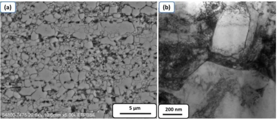
Fig. 4 shows the SEM (Fig. 4 (a)) and TEM (Fig. 4(b)) micrographs of the 80% cold rolled sample followed by annealing at 700 ºC for 300 min. The microstructure consists of mostly UGF austenite as the phase with lighter contrast in the SEM micrograph. Embedded in such a matrix are precipitates in dark contrast which are delta ferrite that was present in the as-received coarse grained 304L stainless steel and was not affected by the cold rolling and annealing. A bimodal distribution of the grain sizes can be easily identified in the UFG austenite matrix. The TEM micrograph in Fig. 4(b) also shows austenite grains with a high density of dislocations.
Fig. 4: SEM and TEM micrograph of the ultrafine grained 304L stainless steel with bimodal structure
3.2. Microstructural observations during friction-stir welding
Friction-stir welding was performed with a constant rotational speed of 630 rpm and different welding speeds of 20 mm/min-160 mm/min. The control of the heat input is very important during FSW of UFG stainless steels as it affects a number of processes such as grain growth, distortion, phase transformation and so on. Therefore, knowledge about the generation and distribution of heat in the welded sample is necessary. Schmidt et al [20] suggested that heat is generated by the friction between the rotating tool and material interface, and so the heat input dQ generated in an element of surface area dA during FSW is given by:
where ωr is the angular speed, M the torque, r the radius, F the normal force, and τcontact the shear contact stress. From this equation, for the tool geometry shown in Fig. 2, the general heat input can be obtained from:
Qtotal = 2
3 𝜋 τcontact ωr (rs3 + 3 rp2Hp)
where rs , rp and Hp are the radius of the shoulder and the radius and length of the pin, respectively . As shown in Fig. 2, the contributions of different parts of the present tool to the total heat generation are as follows:
F
1=
𝑄1 𝑄𝑡𝑜𝑡𝑎𝑙=
𝑟𝑠3− 𝑟𝑝3 (𝑟𝑠3+3 𝑟 𝑝2𝐻𝑝)≅ 90 %F
2=
𝑄2 𝑄𝑡𝑜𝑡𝑎𝑙=
3 𝑟𝑝2 𝐻𝑃 (𝑟𝑠3+3 𝑟 𝑝2𝐻𝑝)≅ 6.8 %F
3=
𝑄3 𝑄𝑡𝑜𝑡𝑎𝑙=
𝑟𝑝3 (𝑟𝑠3+3 𝑟 𝑝2𝐻𝑝)≅ 3.2 %Therefore, the contact between the tool shoulder and the sample surface generates most of the heat, and so the maximum temperature should be observed there [21-24]. The heat propagates downward from the top surface to the interior of the sample and causes material flow from the advancing side (AS) to the retreating side (RS). Fig. 5 shows the SEM micrographs of two different regions along the thickness of the FSW sample at the welding speed of 160 mm/min. The average grain size in the top-surface region and that at the bottom surface are 9 and 5 µm, respectively. These results might confirm that the grain growth happens during the FSW cooling cycle, and the extent of grain growth is larger in the top surface. Considering that there is a grain size gradient through the tickness of the material after FSW, the mid-plane was selected for the
study of the effect of FSW speed on the microstructure and mechanical properties of UFG 304L stainless steel.
Fig. 5: SEM micrographs of the (a) top surface and (b) bottom surface of the sample friction stir welded by the welding speed of 160 mm/min
EBSD measurments were performed to study the on-going events in the front of the rotating tool. The EBSD map of the region exactly in the front of the pin for the welding speed of 20 mm/min is presented in Fig. 6. As before, black, red and green lines indicate HABs, LABs and Σ3 twin boundaries, and blue regions indicate delta ferrite phase. It can be seen that some amount of twin boundaries is present in the sample. The presence of the annealing twins ahead of the welding tool is likely to be due to the high temperature and strains experienced in this region. As 304L stainless steel is a low stacking fault energy material, the annealing twins are very easy to form. In fact in low stacking fault energy materials where dislocation climb becomes difficult at high temperatures, twinning comes into operation to accommodate some portion of deformation. Also grain growth might be another reason for the formation of annealing twins in
this stage. The average grain size of the region in front of the tool was found to 3 µm at welding speed 20 mm/min, and 1.5 µm at welding speed 80 mm/min. No considerable change was observed at welding speed 160 mm/min in comparison with the base metal. Some delta ferrite is also visible in the structure.
Fig. 6: Grain boundary map of the region just ahead of the rotating tool in the sample friction stir welded with the welding speed of 20 mm/min
Fig. 7(a) shows a typical low-magnification cross sectional image of the sample friction-stir welded at 80 mm/min welding speed. The left and right hand sides of the image correspond to
the advancing side (AS) and retreating side (RS) of the rotating tool, respectively. It is clearly seen that no volumetric defect is present in the weld. The macrostructure of the FSW weld consists of several regions: nugget zone (NZ), thermomechanically affected zone (TMAZ), heat affected zone (HAZ) and base metal (BM). There is an obvious interface between the NZ and TMAZ in the advancing side but the interface is not clearly observable in the retreating side. In addition, a banded structure is visible in the nugget zone as marked in Fig. 7 (a) and shown in Fig. 7(b-e). The banded area shows lower corrosion resistance in comparison with other areas of the weld as indicated by its heavily pitted surface.
Fig.7 : Typical low-magnification image of the cross section in the friction stir welding along with higher magnification micrographs of the banded area
Commented [SpUsr1]: Not obvious to me that you can tell these from Fig. 7a. Can you label these in Fig. 7a?
Commented [SpUsr2]: Again, not obvious to me what interface you are referring to in Fig. 7a. May be better after you have added the labels above.
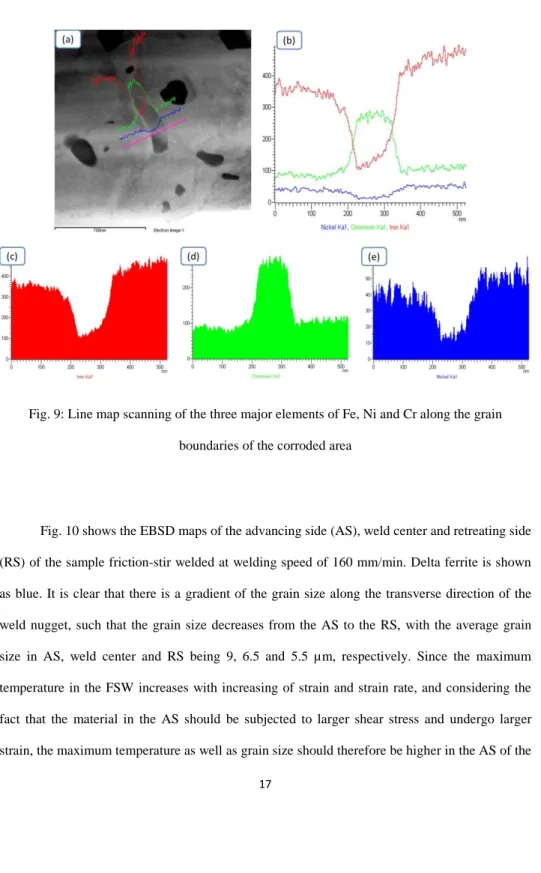
TEM samples were prepared from the corroded and uncorroded regions of the banded area shown in Fig. 7 (b), in order to study their microstructural differences. Fig. 8(a-b) and Fig. 8(c-d) show the TEM micrographs of the corroded and uncorroded regions, repectively. In the corroded region, nanometric precipitates of size 100 nm or less were present, both inside the grains and on the grain boundaries, and in some cases, these particles form a continous precipitate structure on the grain boundaries (Fig.8 (a)). EDS analysis showed that these particles are Cr rich containing 56.3 % Fe, 39% Cr, 2.6% Ni and 2% Mn in comparison with austenite matrix containing 72.3% Fe, 18.54% Cr, 7.88% Ni and 1.28% Mn. Line profiles of the three major elements (Fe, Cr and Ni) were performed along the grain boundary of Fig.8 (a) and the results are presented in Fig.9 (a-e), which confirm that these precipitates are choromim rich with reduced amounts of Fe and Ni. Since no sign of carbon was detected in the EDS spectra of these particles so these particles cannot be chromium rich carbides. The chemical composition of the particles suggests that they are sigma phase. Sigma phase is an intermetallic compound in the Fe-Cr binary phase diagram containing 30 to 50 wt.% Cr with a tetragonal crystal structure, and can form in the temperature range of 600 0C to 1000 0C, which completely matches the thermal conditions of FSW [25]. The
sigma phase can form by decomposition directly from austenite, or through a transformation from delta ferrite [25-27]. Direct transformation of austenite to sigma phase requires very long time (normally more than 100h) because substantial diffusion of chromuim atoms in austenite is needed [25]. It has been reported that the presence of a duplex microstructure containing delta ferrite and austenite can accelerate the sigma phase formation [26-27]. Normally delta ferrite is a Cr rich region compared to austenite. Also the BCC structure of delta ferrite with a lower atomic packing factor in comparison with FCC austenite can faciliate Cr diffusion.
Fig. 8 : TEM micrographs of the corroded region (a-b) and uncorroded region (c-d) of the banded area shown in Fig.7 (b)
Fig. 9: Line map scanning of the three major elements of Fe, Ni and Cr along the grain boundaries of the corroded area
Fig. 10 shows the EBSD maps of the advancing side (AS), weld center and retreating side (RS) of the sample friction-stir welded at welding speed of 160 mm/min. Delta ferrite is shown as blue. It is clear that there is a gradient of the grain size along the transverse direction of the weld nugget, such that the grain size decreases from the AS to the RS, with the average grain size in AS, weld center and RS being 9, 6.5 and 5.5 µm, respectively. Since the maximum temperature in the FSW increases with increasing of strain and strain rate, and considering the fact that the material in the AS should be subjected to larger shear stress and undergo larger strain, the maximum temperature as well as grain size should therefore be higher in the AS of the
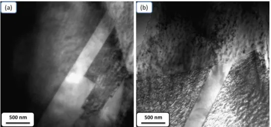
weld [10]. Another important feature that can be observed from Fig. 10 is that the amount of delta ferrite is different in these three regions. The amount of delta ferrite is remarkably higher in the RS rather than AS. Increasing the temperature during the thermal cycle of FSW along with high strain and strain rate in the process may dissolve some of the pre-existing delta ferrite in the austenite matrix, and since the temperature is higher in the AS in rather than the RS, more delta ferrite got dissolved in the AS leading to a lower residual content there. Some amount of twin boundaries can be seen in the weld nugget microstructure. Fig. 11 shows TEM micrographs of different typical twin morphologies in the weld nugget of a sample welded at the welding speed of 160 mm/min. These twins have straight and parallel boundaries which elongate throughout the grain from a grain boundary. These twins are likely annealing twins instead of mechanical twins which normally show lenticular morphology with nanometric width It has been shown that the plastic deformation during stirring in the weld nugget can effectively destroy all existing twins [28]. Therefore, the presence of annealing twins in the weld nugget microstructure can be due to the post dynamic recrystallization phenamena like grain growth or grain boundary migration induced by static recrystallization after welding. Some of these twins are located inside austenite grains with lower dislocation densities than other twin free grains. As the thermal conductivity of austenitic stainless steels is small, the cooling cycle can be relatively long, and the existence of twins inside grains with low dislocation density can be indicative of the fact that some degree of static recrystallization has happened during the cooling cycle. The existence of post dynamic recrystallization phenomena especially static recrystallization during the FSW cooling cycle of 304L stainless steel was reported previously by Sato et al. [29].
Fig.10: Grain boundary map in midplane of weld nugget for the sample welded with the welding speed of 160 mm/min: (a) advancing side (b) weld center and (c) retreating side.
Fig. 11 : TEM micrographs of typical annealing twins observed in the stirred zone of a sample welded at the welding speed of 160 mm/min.
Fig. 12 shows the EBSD microstructures of the weld nugget center of samples welded at speeds 20 and 80 mm/min. The stirred zone in both samples consists of equiaxed austenite grains with an average grain size of 21 and 10.5 µm at welding speeds of 20 and 80 mm/min, respectively. The microstructure of the weld nugget depends on the peak temperature and cooling rates during FSW. Meanwhile, these factors are controlled by processing parameters such as the rotational and welding speed that can finally determine the total heat input during FSW. It is clear that the excess heat input at the welding speed of 20 mm/min can cause accelerated grain growth and finally larger grain size after FSW.
Fig. 12: EBSD maps of the microstructures of the weld nugget center of samples friction-stir welded at speed of (a) 20 mm/min and (b) 80 mm/min.
Fig. 13 (a) shows a low-magnification TEM micrograph of the weld center for the sample welded at 80 mm/min. Coarse austenite grains as well as smaller subgrains can be seen in the microstructure. The elongated phase in the microstructure was identified as delta ferrite with BCC structure. Fig. 13 (b) shows a high-magnification TEM image from the delta ferrite phase. This elongated phase is normally 500 nm in length and less that 200 nm in width. It should be noted that the existence of delta ferrite in the austenitic microstructure can promote sigma phase precipitation.
Fig. 13: (a) Low-magnification TEM montage micrograph of the weld center for the sample welded at the welding speed of 80 mm/min; (b) higher magnification showing elongated delta
ferrite in the austenite matrix.
Friction stir welding processes normally produce complex and three dimensional material flow patterns. It has been reported that the deformation introduced by the rotating tool during friction stir welding is predominantly in the form of simple shear [30], and so the resultant texture typically shows ideal simple shear texture components [30]. Unlike conventional deformation modes such as rolling, tension and compression, the samples of which are readily aligned with
the deformation frame of reference which is constant across the entire sample, the shear deformation introduced during FSW is almost never aligned with the sample coordinate system, and the shear orientation during FSW varies as a function of position in the welded regions. For this reason, as proposed by Fonda et al. [30-31], it is better to use the shear coordinate system rather than the normal frame (WD, TD, ND) to present the texture produced during friction stir welding. The shear coordinate system is defined by the shear direction (SD), the shear plane normal (SPN), and the rotation access direction (𝑅𝐴⃗⃗⃗⃗⃗ = 𝑆𝑃𝑁⃗⃗⃗⃗⃗⃗⃗⃗ × 𝑆𝐷⃗⃗⃗⃗⃗ ). At any specific location in the weld the difference between the acquired texture orientation and the local orientation of the shear surface can be represented by two angles, α and β. The SD deviates from the welding direction as a function of position across the weld by the angle α, which is defined by [31]: 𝛼 = 𝑠𝑖𝑛−1( 𝑥
𝑟𝑒𝑓𝑓)
where α is the angle between WD and the projection of SPN onto this plane, x is the distance from the weld centerline to the area of interest, and reff is the weld nugget radius. The angle β
that is required to represent data in the shear reference frame represents the deviation of 𝑅𝐴⃗⃗⃗⃗⃗ from vertical or the deviation of 𝑆𝑃𝑁⃗⃗⃗⃗⃗⃗⃗⃗ from the top-view plane of the sample. Because the shape of shear surface can be approximately obtained by rotation of the trace of the weld nugget boundary, β corresponds to the inclination of this boundary. This angle can be measured from the shape of weld nugget boundary in transverse cross section (ND-TD plane) [31].
Fig.14 shows the (111) and (101) pole figure and also ODF cross sections of the weld nugget center for the sample welded at 80 mm/min after necessary rotations. In this paper Euler section representation is used due to the higher resolution relative to pole figures. The main focus is on the two sections 𝛷2 = 0 and 𝛷2 = 45 which is particularly important in steel processing. The
textures presented as Euler cross sections are compared to the ideal shear textures of FCC materials [32-33] (Fig.15) in order to identify the components. The most important ideal orientations in simple shear are found to be distributed along the two fibers with a crystallographic slip direction parallel to the shear direction and a crystallographic slip plane parallel to the shear plane, respectively. For fcc materials, they are the {ℎ𝑘𝑙}<110> fiber and {111}<uvw> fiber. It can be seen that the main texture in the weld center is a mixture of the B/𝐵̅ and A* (A*
1 / A*2) components, thus confirming previously reported results that the texture inside
the weld nugget is a kind of simple shear. One of the most important findings here is the lack of rotated cube texture. The shear deformation texture observed here is characteristic of dynamic recovery (DRV) and continuous dynamic recrystallization (CDRX), while rotated cube texture is known to be a result of nucleation and grain growth during discontinuous dynamic recrystallization (DDRX) in 304L stainless steel [33-34]. The absence of rotated cube texture therefore indicates that DDRX is not operative during friction stir welding of the present material.
Fig. 15: Main ideal orientation in simple shear deformation of FCC materials [32-33]
Fig. 16 shows the microhardness profile along the transverse direction of the cross section of the weldmens produced with different welding speeds. It should be noted that the average hardness of the UFG base metal is 330 HV0.5kg . It can be seen from the microhardness data that the
hardness distribution in the weld nugget region is mostly uniform with just small differences between the AS and RS. The average microhardness of the weld nugget region is 190 HV0.5kg,
285 HV0.5kg and 315 HV0.5kg for the welding speed of 20mm/min, 80 mm/min and 160 mm/min,
respectively, and increasing the welding speed also leads to lowering of the grain size. To see if the hardness increment at increasing welding speed is due to the change in grain size according to the Hall-Petch effect, Fig. 17 shows the Hall-Petch plot of the data sets obtained from different welding speeds. As can be seen the relation between hardness and d-1/2 is not linear, indicating
that the hardness increase in the weld nugget cannot be explained simply by a grain size reduction effect. In addition to grain size reduction, high amount of dislocation density caused due to the CDRX as well as sub-boundaries can also affect the hardness of the weldments. It is therefore likely that both grain size reduction and dislocations density as well as sub-boundries
can be effective in obtaining acceptable hardness of the weld nugget in comparison with the base metal. The presence of the sigma phase inside the weld nugget can also be one of the reasons of mechanical property enhancement. The microhardness of the sample welded at speed 160 mm/min is very close to that of the base metal, confirming that FSW can be an effective way for joining advanced ultrafine/nano grained alloys without affecting their properties.
Fig. 16: Microhardness distribution along the transverse direction of the friction stir welded samples at different welding speeds. Error bars mean standard deviations from 5 repeated
Fig. 17: Hall-Petch relation of the data set obtained in the experiments.
4. Conclusions
The microstructural evolution during friction-stir welding of ultrafine grained 304L stainless steel was characterized in this work. The most important results are as follows:
1- The grain structure in the weld nugget region is not homogenous due to the asymmetry in the heat generation between the advancing and retreating sides of the rotating tool during FSW.
2- Substantial grain growth was observed during the thermal cycle of the FSW, with the grain size of the region ahead of the welding tool grown to a large value of about 3 µm for the high heat input condition. Increasing the welding speed can reduce the amount of grain growth.
3- Sigma phase precipitation was identified in the banded structure inside the weld nuggetat both grain boundaries and grain interiors.
4- Increasing the welding speed can decrease the final grain size of the weld nugget and improve the mechanical properties of the weld. Hardness was found to increase in the weld nugget due to both grain size reduction and the presence of dislocations and sub-boundaries in the weld nugget.
5- Shear textures were clearly identified in the weld center. The lack of rotated cube texture in the ODF sections shows that the discontinuous dynamic recrystallization (DDRX) is not active in the final microstructure.
5. References
[1] J.R. Davis, ASM Specialty Handbook: Stainless Steel, Met al.s Park, OH, 1994.
[2] L.P. Karjalainen, T.Taulavuori, M. Sellman, A. Kyröläinen, Some Strengthening Methods for Austenitic Stainless Steels, Steel res int., 2008, 79 (6), 404-412.
[3] S.Sabooni, F.karimzadeh, M.H,Enayati, “ Thermal stabillity study of ultrafine grained 304L stainless steel produced by martensitic process”, Journal of materials engineering and performance, Vol 23(5), (2014), pp 1665-1672.
[4] R.Nafar Dehsorkhi, S.Sabooni, F.Karimzadeh, A.Rezaeian, M.H.Enayati, “The effect of grain size and martensitic transformation on the wear behavior of AISI 304L stainless steel”, Material and design, Vol.64, (2014), 56-62.
[5] R. Song, D. Ponge, D. Raabe, J.G. Speer, D.K. Matlock, Overview of processing, microstructure and mechanical properties of ultrafine grained bcc steels, Mater Sci. Eng. A, 2006, 441(1-2), 1–17.
[6] R. Ueji, H. Fujii, L. Cui, A. Nishioka,K. Kunishige, K. Nogi, Friction stir welding of ultrafine grained plain low-carbon steel formed by the martensite process, Mater Sci. Eng. A, 2006, 423, 324–330.
[7] Y.Weng editor, “Ultrafine grained steels”, Springer, Beijing, 2009.
[8] Yun Peng, Zhiling Tian, Changhong He, Xiaomu Zhang and Hongjun Xiao Effect of Welding Thermal Cycle on the Microstructure and Mechanical Properties of Ultra-fine Grained Carbon Steel, Mater Sci Forum, 2003, 426-432 , 1457-1462.
[9] Hideki Hamatani , Yasunobu Miyazaki, Tadayuki Otani, Shigeru Ohkita, and Environmental Conscious Ultra-Fine-Grained Steel Consortium of JRCM (The Japan Research and Development Center of Metals), Minimization of heat-affected zone size in welded ultra-fine grained steel under cooling by liquid nitrogen during laser welding, Mater Sci. Eng. A, 2006, 426, 21–30.
[10] R. Nandan , T. DebRoy , H.K.D.H. Bhadeshia, “Recent advances in friction-stir welding – Process, weldment structure and properties”, Prog. Mater Sci., 2005, 53, 980–1023.
[11] M. C. Chaturvedi, Welding and joining of aerospace materials, Woodhead publishing, 2012.
[12] W.Y. Li, T. Fu, L. Hütsch, J. Hilgert, F.F. Wang, J.F. dos Santos, N. Huber, Effects of tool rotational and welding speed on microstructure and mechanical properties of bobbin-tool friction-stir welded Mg AZ31, Materials & Design, Vol. 64, 2014, 714-720.
[13] Yong Zhao, Zhengping Lu, Keng Yan, Linzhao Huang, Microstructural characterizations and mechanical properties in underwater friction stir welding of aluminum and magnesium dissimilar alloys, Materials & Design, Vol. 65, (2015), 675-681.
[14] Mohsen Bahrami, Kamran Dehghani, Mohammad Kazem Besharati Givi, A novel approach to develop aluminum matrix nano-composite employing friction stir welding technique, Materials & Design, Vol. 53, (2014), 217–225.
[15] R Rai, A De, H K D H Bhadeshia, T DebRoy, Review: friction stir welding tools, Sci Technol Weld Joi., 2011, 16(4), 325 – 342.
[16] S.Sabooni, F.karimzadeh, M.H,Enayati, “ Thermal stabillity study of ultrafine grained 304L stainless steel produced by martensitic process”, J. Mater. Eng. Perform., 2014, 23(5), 1665-1672.
[17] K. Nohara, Y. Ono, N. Ohashi, Composition and grain-size dependencies., Journal of Iron and Steel Institute of Japan, 63, 1977, p 212–222.
[18] R.D.K. Misra, Z. Zhang, P.K.C. Venkatasurya, M.C. Somani, L.P. Karjalainen, Martensite shear phase reversion-induced nanograined/ultrafine-grained Fe–16Cr–10Ni alloy: The effect of interstitial alloying elements and degree of austenite stability on phase reversion, Materials Science and Engineering: A, Vol. 527( 29–30), (2010), 7779-7792.
[19] R. D. K. Misra, J. S. Shah, S. Mali, P. K. C. Venkata Surya, M. C. Somani, L. P. Karjalainen, Phase reversion induced nanograined austenitic stainless steels: microstructure, reversion and deformation mechanisms, Materials Science and Technology, Vol. 29(10), 2013, 1185 – 1192.
[20] H. Schmidt, J. Hattel, J. Wert, Modell. Simul. Mater. Sci. Eng. 12 (2004) 143.
[21] A. Rahmati Darvazi, M. Iranmanesh, Thermal modeling of friction stir welding of stainless steel 304L, Int J Adv Manuf Technol, 2014, Vol. 75(9-12) ,1299-1307.
[22] X.K. Zhu, Y.J. Chao, Numerical simulation of transient temperature and residual stresses in friction stir welding of 304L stainless steel, Journal of Materials Processing Technology, 146 (2004) 263–272.
[23] D Lohwasser, Z.Chen, Friction stir welding: from basics to application, Woodhead publishing, 2009.
[24] M. Z. H. Khandkar; J. A. Khan; A. P. Reynolds, Prediction of temperature distribution and thermal history during friction stir welding: input torque based model, Science and Technology of welding and joining, Vol. 8(3), (2003), 165-174.
[25] Chih-Chun Hsieh Weite Wu, Overview of Intermetallic Sigma (σ) Phase Precipitation in Stainless Steels, ISRN Metallurgy, Volume 2012, Article ID 732471, p 1-16.
[26] J.M.Vitek, S.A.David, Sigma phase transformation in austenitic stainless steel, Welding journal, (1984), Vol. 63(8) , 246.
[27]S.H. C. Park, Y. S. Sato, H. Kokawa,Z., S. Hirano, M. Inagaki, Rapid formation of the sigma phase in 304 stainless steel during friction stir welding, (2003), Vol. 49(12), 1175–1180.
[28] S.Mironov, Y.S.Sato, H.Kokawa, H.Inoue, S. Tsuge, structural response of superaustenitic stainless steel to friction stir welding, Acta. Mater., (2011), 59, 5472-5481.
[29] Y.S.Sato, T.W.Nelson, C.J.Sterling, Recrystallization in type 304L stainless steel during friction stirring, Acta. Mater., (2005), 53, 637-645.
[30] R. W. Fonda, K. E. Knipling, Texture development in friction stir welds, Science and Technology of welding and joining, Vol. 16(4), 2011, 288-294.
[31] R. W. Fonda, K. E. Knipling, D. J. Rowenhorst, EBSD Analysis of Friction Stir Weld Textures, The Journal of The Minerals, Metals & Materials Society (JOM), Vol. 66(1), 2014, 149-155.
[32] Saiyi Li, Irene J. Beyerlein, Mark A.M. Bourke, Texture formation during equal channel angular extrusion of fcc and bcc materials: comparison with simple shear, Materials Science and Engineering A 394 (2005) 66–77.
[33] Ph.Bocher, J. Azar, B.L.Adams, J.J.Jonas, Using OIM to interpret the dynamically recrystallized texture of a low stacking fault energy FCC material, Materials Science Forum Vols. 273-275 (1998) pp 249-254.
[34] Nelson, Benjamin D., "Using Design of Experiments and Electron Backscatter Diffraction to Model Extended Plasticity Mechanisms In Friction Stir Welded AISI 304L Stainless Steel" (2010). All Theses and Dissertations. Paper 2582.