The Direct-to-Data (D2D) Cache:
Navigating the Cache Hierarchy with a Single Lookup
Andreas Sembrant, Erik Hagersten, and David Black-Schaffer
Uppsala University, Department of Information Technology
P.O. Box 337, SE-751 05, Uppsala, Sweden
{andreas.sembrant, erik.hagersten, david.black-schaer}@it.uu.se
Abstract
Modern processors optimize for cache energy and perfor-mance by employing multiple levels of caching that address bandwidth, low-latency and high-capacity. A request typically traverses the cache hierarchy, level by level, until the data is found, thereby wasting time and energy in each level. In this paper, we present the Direct-to-Data (D2D) cache that locates data across the entire cache hierarchy with a single lookup.
To navigate the cache hierarchy, D2D extends the TLB with per cache-line location information that indicates in which cache and way the cache line is located. This allows the D2D cache to: 1) skip levels in the hierarchy (by accessing the right cache level directly), 2) eliminate extra data array reads (by reading the right way directly), 3) avoid tag comparisons (by eliminating the tag arrays), and 4) go directly to DRAM on cache misses (by checking the TLB). This reduces the L2 latency by 40% and saves 5-17% of the total cache hierarchy energy.
D2D’s lower L2 latency directly improves L2 sensitive ap-plications’ performance by 5-14%. More significantly, we can take advantage of the L2 latency reduction to optimize other parts of the micro-architecture. For example, we can reduce the ROB size for the L2 bound applications by 25%, or we can reduce the L1 cache size, delivering an overall 21% energy savings across all benchmarks, without hurting performance.
1. Introduction
The cache hierarchy in modern processors consumes 12 - 45% of the core power [17]. Typically, each cache level is unaware of what data the other levels contain. A request must therefore traverse the cache hierarchy, level-by-level, until the data is found. This wastes energy by probing levels that do not contain the data, and increases access latency for every level examined. Moreover, L2 and L3 caches are typically accessed in two phases to save energy: first the tags are read and compared, and then only the matching way is read. This saves data array lookup energy since only data from the correct way is read, but increases latency even further.
To address the inefficiency of having to traverse the whole hierarchy to find data, we propose the Direct-to-Data (D2D) cache design. This design uses a single lookup to an extended L1 TLB (the eTLB) to identify the cache level and way for the desired data. As a result we can eliminate the energy and
latency overhead of traversing the cache hierarchy and the cost of tag comparisons. Because the D2D design removes the need for tag lookups in the L2 cache, it reduces L2 latency by 40% (4 cycles) compared to a standard 10-cycle phased L2 cache (4c tags + 6c data). Accesses to DRAM also experienced re-duced latency, as the eTLB lookup contains information about cache lines that do not reside in any cache, thereby allowing such accesses to bypass the whole cache hierarchy and di-rect access to DRAM on cache misses. The reduced latency directly improves L2 sensitive application’s performance by 5-14%.
More importantly, the D2D cache achieves this without in-creasing static or dynamic energy. In fact, the D2D cache reduces cache energy by 5% on average compared to stan-dard tag-array-based cache designs. This savings comes from only probing the cache levels that contain the data and by eliminating the tag arrays.
Aside from improving L2 sensitive applications’ perfor-mance, D2D’s shorter cache latency enables us to make other micro-architectural trade-offs. For example, we can shrink the L1 cache size, thereby moving some of the applications work-ing set into L2, without hurtwork-ing performance compared to a traditional hierarchy. This saves 21% of the total cache energy for the applications that fit their working set in the smaller L1 cache, without hurting the other application’s performance. Beyond shrinking the cache size, we can also shrink the ROB size by 25% for L2-bound applications, since the D2D’s re-duced L2 latency means fewer out-of-order instructions are required to hide the L2 latency.
2. Navigating the Cache Hierarchy with D2D
The goal of the D2D cache is to directly determine the cache level and way for the requested data with a single lookup. To do so, the first lookup must also know if, and where, the data is located in the lower level caches. To do so, we build on two techniques: coarse-grained cache-line tracking and extended TLBs.
Coarse-grained tracking. Caches typically pair each cache line with its own tag. This makes it easy to track cache lines, but is not optimal in terms of storage, since the cache lines belonging to the same physical page will duplicate the page information in their tags. Zebchuk et al. [20] and Sem-brant et al. [15] instead track cache lines with coarse-grained
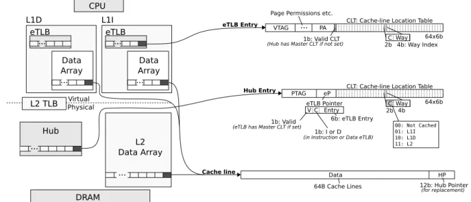
Virtual Physical eTLB Data Array L1D CPU Hub L2 TLB ... DRAM L2 Data Array ... ... ... VTAG ... C Way PA
CLT: Cache-line Location Table
4b: Way Index eTLB Entry 1b: Valid CLT 2b PTAG C Way eP 4b Hub Entry 2b 00: Not Cached 01: L1I 10: L1D 11: L2 V Entry 6b: eTLB Entry 1b: Valid C 1b: I or D HP Data Cache line 12b: Hub Pointer eTLB Pointer ... ... L1I Data Array eTLB
CLT: Cache-line Location Table
64B Cache Lines Page Permissions etc.
64x6b
(eTLB has Master CLT if set)
(in Instruction or Data eTLB)
64x6b
(Hub has Master CLT if not set)
(for replacement)
Figure 1: D2D Cache Components. structures (regions [20] or pages [15]). Each such region or
page stores a valid bit for each of its cache lines indicating if the cache line is present in the cache, and way-information indicating in which way the cache line is located. A cache access is then done in two phases: first the cache line’s way information is read from the region array, then the correct data array is accessed. Tracking cache lines with coarse-grained structures requires less tag area compared to a tag-based cache. Zebchuk et al. [20] use coarse-grained tracking to reduce L2 tag-area, eliminate snoops, and for prefetching, and Sem-brant et al. [15] use it to reduce the dynamic energy in L1 caches by reading only the correct way from the data array.
Extended TLB (eTLB).The TLB is a coarse-grained data structure that tracks address translations. Hagersten et al. [6], Boettcher et al. [3] and Sembrant et al. [15] extend the TLB with cache line way information as described above to reduce the L1 cache energy. Since, every cache access is preceded by a TLB lookup, only the correct way has to be read from the L1 cache. Thus, saving energy compared to parallel L1 caches that access the tags and the data in parallel. Hager-sten et al. [6] and Boettcher et al. [3] do not remove the tag array, but keep it and treat the TLB way information as hints, whereas Sembrant et al. [15] provide accurate tracking and can therefore eliminate the tag array. To do so, they require that each valid cache line have a valid entry in the eTLB.
The D2D cache extends the eTLB to navigate the cache hierarchy with a single lookup. To do so, D2D extends the TLB with both way information and cache-level information. Since, the TLB reach is typically larger than the L1 cache size (e.g., 256kB reach with 64 entries 4 kB pages), it can naturally track parts of the data in the L2 cache as well.
To make the D2D cache practical, it must also handle syn-onyms in the L1 caches and the transition from virtual ad-dresses in the L1 cache to physical adad-dresses in the L2 cache. Furthermore, L2 and last level caches typically contain both
data and instructions. The D2D cache must therefore also be able to track data movement in both the separate L1I and L1D caches, and the unified L2 cache. D2D must also be able to handle shared caches. All these issues are handled in Section 2.5.
2.1. Overview
Figure 1 shows an overview of D2D’s different components. We focus on a two-level cache hierarchy for simplicity, but D2D can readily be extended to deeper cache hierarchies. The L1I and L1D caches both have eTLBs and data arrays. There is a second-level TLB for address translations that miss in the eTLBs. The boundary between virtual and physical addresses is shown by the dashed line cutting the L2 TLB.
eTLB.In addition to virtual (VTAG) to physical address translations (PA) and standard page permissions, the eTLB holds a Cache-line Location Table (CLT) for each page. The CLT provides cache line location information for all the cache lines belonging to the same page. Each entry in the CLT contains location data for one of the cache lines in the page. The per cache line data consists of 2 bits to indicate where the data is stored (Not Cached, L1I, L1D, or L2) and way index information indicating in which way the cache line is located. The number of way index bits is determined by the highest cache associativity in the hierarchy (typically the last level cache). In our evaluation, we use a 1 MB 16-way L2 cache, therefore need 4 way index bits.
Hub.The Hub functions as both a second-level storage for cache line locations (CLT) and as a entry point for coherency and external requests using physical addresses. A second-level CLT storage could have been added to the L2 TLB, but such an approach would require reverse address translation and complicated synonym handling since the L2 TLB is virtually indexed (see Section 2.5). Instead, we use a separate struc-ture that is physically tagged (PTAG). We call it the Hub to
Hub L2 Hub L2 Virtual Physical eTLB Data Array L1D L1D CPU Hub L2 TLB ... DRAM
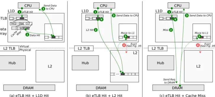
(a) eTLB Hit + L1D Hit Data Hit
CPU
L2 TLB
...
DRAM
(b) eTLB Hit + L2 Hit L2 Hit2
CPU
L2 TLB
DRAM
(c) eTLB Hit + Cache Miss L2 Send Req. to DRAM ... 1 eTLB Hit Send Data to CPU 3 TAG... CLT ...C W Cach e Way C W PA 2 ... ... 1 eTLB Hit
Send Data to CPU
3 4 Move to L1 5 Evict (See Fig. 3f) L1D Miss 2 ... ... 1 eTLB Hit
Send Data to CPU
3
Move to L1
5
4(See Fig. 3f)Evict
6 6
Figure 2: D2D Cache Examples: eTLB Hit
distinguish it from the regular L2 TLB.
Cache line.Each cache line is extended with a Hub pointer (HP) containing the location of the page in the Hub to which the cache line belongs. The pointer is only used during re-placement to identify the CLT to update. Note that the Hub pointers are significantly smaller than standard tags (12 bits for a 4k entry Hub vs.≈28 bits tags), and are only accessed during replacement, which is off the critical path.
Cache line tracking.D2D tracks a cache line’s cache level and way location in either the eTLB or the Hub at any given time to save energy and to simplify the design. If the eTLB has the active CLT (the CLT valid bit is set), only the eTLB’s CLT contains the up-to-date cache line location information, otherwise the Hub’s CLT contains the information. To support this, each entry in the Hub has an eTLB pointer (eP) iden-tifying the location of its corresponding eTLB entry. If the eTLB pointer is set, the valid cache location information is found in the eTLB’s CLT, otherwise in the Hub’s CLT. That means, only one of the CLTs needs to be updated on cache line replacement.
The D2D cache enforces an exclusive cache hierarchy, meaning that a cache line can only be in either the L1 cache or the L2 cache, but not in both at the same time. D2D therefore only needs to keep track of one cache line location at any given time, thereby reducing number of pointers in the cache line location tables.
Invariant. The D2D cache has one invariant: all cache lines must belong to a valid page in the Hub (i.e., the cache line’s Hub pointer always points to a valid page in the Hub). This is required to always know where all the cache lines are located in the hierarchy.
Examples. We will now describe the D2D cache’s func-tionally by walking through the set of examples in Figure 2
and Figure 3. The figures shows annotated versions of cache design, with the L1I removed for better readability (its opera-tions are equivalent to the L1D). Example 1 describes how to access data in the cache (the most common operation), Exam-ple 2 describes how an eTLB miss is handled, and ExamExam-ple 3 describes how a cache line is evicted. The access frequencies are taken from the evaluation (See section 4).
2.2. Example 1: eTLB Hit
In Figure 2a,b,c), the CPU sends a data request to the D2D cache. The request hits in the eTLB 1, and the cache line’s cache-level and way information are read.
eTLB Hit + L1 Hit [94% of memory accesses]. In Fig-ure 2a), the cache-level bits in the CLT entry indicate that the data is in the L1 cache. The L1 data-array is then accessed with the set index from the virtual address and the way index stored in the eTLB’s cache-line location table (CLT) 2. The D2D cache accesses the correct L1 data array directly and sends the data to the CPU 3. Note that the set index from the virtual address is used to identify the correct cache line in the CLT, meaning that only 6 bits of the CLT (384 bits) needs to be read. Moreover, the physical address in the eTLB is not needed since the correct way is determined by the way information from the CLT (and not by comparing tags).
Summary: In this case, the single eTLB access allowed a direct read of the correct L1 way.
eTLB Hit + L2 Hit [3% of memory accesses]. In Fig-ure 2b), the cache-level bits in the CLT entry indicate that the data is in the L2 cache. The L2 data-array is physically indexed and accessed by combining: 1) parts of least signif-icant bits of the virtual address, 2) the parts of the physical address bits from the eTLB (4 bits for 1MB 16way L2), and 3) the way index bits stored in the eTLB’s cache-line location
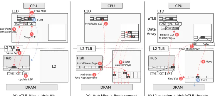
Hub CPU eTLB Data Array L1D ... ... TAG... CLT ...C W C W PA L2 TLB DRAM
(f) L1 eviction + Hub/eTLB Update
Find Set 2 TAG 3 Move 4 HP DATA ... ... Evict eP CLT 1 Read Hubpointer Update CLT to point to L2 5 CPU L2 TLB ... DRAM
(e) Hub Miss + Replacement
Hub Miss Find Replacement ... ... L2 Hub ... ... ... ... 1 4
Install New Page Flush 2 Evicted Page L1D ... ... 3 Invalidate CLT L1D 5 CPU L2 TLB DRAM
(d) eTLB Miss + Hub Hit
eTLB Miss 1 ... ... TAG...PA CLT 2 Evict 3 Copy Page Permission etc. L2 4 VA to PA ... Hub TAG ... eP CLT 6 Update L1P Copy CLT L2
Figure 3: D2D Cache Examples: eTLB Miss
table (CLT) 2. The D2D cache accesses the L2 data array and sends the data to the CPU 3. The data is then installed into the L1 cache by first evicting a cache line from the L1 cache
4, and then migrating the data from the L2 cache into the L1 cache and updating the Hub pointer (HP) to point to the cache line’s page in the Hub 5. The CLT is updated to point to the new location in the L1 cache 6.
Summary: Here the eTLB access allowed a direct read of the L2 data-array without requiring either L1 or L2 tag checks. eTLB Hit + Cache Miss [2% of memory accesses]. In Figure 2c), the cache-level bits indicate that the data is not in any of the caches. D2D then reads the physical address from the eTLB, and sends a memory request directly to the DRAM controller 2. The data is fetch from memory, and D2D sends the data to the CPU 3. The data is then installed into the L1 cache by first evicting a victim from the L1 cache
4, and then moving the data into the L1 cache and updating the Hub pointer (HP) to point to the cache line’s page in the Hub 5. The CLT is updated to point to the new location in the L1 cache 6.
Summary: Here the eTLB information allowed a direct DRAM access thereby bypassing the entire cache hierarchy. 2.3. Example 2: eTLB Miss
The CPU sends a data request to the D2D cache, but the request misses in the eTLB because either the eTLB page is missing, or the CLT’s valid bit is not set indicating that the Hub has the active CLT. The cache line location information must therefore be fetched from the Hub. However, this happens rarely since most accesses hit in the eTLB.
eTLB Miss + Hub Hit [0.7% of memory accesses]. In Figure 3d), the CPU request misses in the eTLB 1. An eTLB victim is selected and evicted by writing its active CLT data
to the Hub, and invalidating the Hub’s eTLB pointer (eP) to indicate that the page is no longer in the eTLB 2. The physical address and page permissions etc. are fetched from the L2 TLB 3. The Hub is physically addressed, and is therefore accessed by first doing a virtual to physical address translation in the L2 TLB 4. The Hub is then accessed, and its CLT is copied to the eTLB 5. Finally, the eTLB pointer in the Hub is updated to point to the eTLB entry indicating that the eTLB now has the active CLT 6.
Summary: Here the eTLB miss forced D2D to go to the Hub to find the cache line location information. D2D needs to translate the virtual address with the L2 TLB first to access the physically addressed Hub.
eTLB Miss + Hub Miss [0.4% of memory accesses]. In Figure 3e), in addition to an eTLB miss, the CPU request miss in the Hub, and a Hub entry must be evicted to provide space for the new entry 1. To maintain consistency, all the cache lines belonging to the evicted Hub entry’s page must also be evicted, since cache lines are tracked by the information in the page’s CLT and if the CLT is evicted, there would be no way to locate the data (this is the trade-off for removing tags). To do so, D2D walk through the evicted page’s CLT in order to find and evict its cache lines 2. The eTLB’s CLT is then invalidated 3. Finally, the new page is installed into the Hub with its CLT information set to Not Cached 4.
Summary: Here the D2D cache invariant required that all the data belonging to the evicted Hub page is flushed from the cache.
2.4. Example 3: Cache line Eviction
Figure 3f) shows how a cache line is evicted from the L1 cache to the L2 cache. To do so, D2D must updated the evicted cache line’s CLT entry to point to the new location in the L2 cache,
and D2D must move the data to the L2 cache. This is off the critical path.
Cache line Eviction [4.5% of memory accesses, off crit-ical path]. A L1 victim is selected. D2D first accesses the evicted cache line’s Hub pointer (HP) 1. It contains the iden-tity of the Hub entry associated with it. Since both the Hub and the L2 cache are set-associative structures, a subset of HP can be used to identify the L2 set where the L1 victim should be placed 2. One cache line from this L2 set is evicted to make room for the L1 victim 3. The L1 victim is then be moved from the L1 to the L2 cache 4. Finally, the L1 victim’s CLT entry is updated to point to the new location in the L2 by following its eTLB pointer (eP) to the active CLT 5.
Summary: To evict a cache line, we use its Hub pointer (HP) to find its CLT entry to update. To find the active CLT in the eTLB or the Hub, we use the Hub entry’s eTLB pointer (eP).
2.5. Compatibility
The goal of the D2D hierarchy is to work as drop-in replace-ments for standard cache hierarchies. That means it should be possible to use the D2D cache without requiring modifications to the processor core or software. To do so, D2D must handle synonyms, JITed/dynamically generated code, large pages, atomicity, and coherency.
Synonyms. Synonyms occurs when several virtual ad-dresses map to the same physical address. D2D allows only one active synonym CLT at any given time. Multiple syn-onyms are therefore not allowed in the eTLB. To handle this, D2D checks for synonyms in the eTLB on eTLB replacement and disables accesses using the old synonym.
Since the Hub is physically indexed, this means that all synonyms in the eTLB map to the same entry (physical page) in the Hub. On an eTLB miss, the physical address from the L2 TLB is used to access the Hub. If the eTLB pointer (eP) already points to a entry in the eTLB, we know that a synonym exists in the eTLB, but under a different virtual address. If the virtual address was the same, we would not have had an eTLB miss. The old synonym’s CLT is then copied to the new synonym’s CLT and then invalidated. The eTLB pointer is then updated to point to the new synonym’s entry in the eTLB. This process requires updating the eTLB, but the cache lines in L1 do not move.
JITed code.Many applications and runtimes generate code that is then executed. Data will then move from the L1 data cache to the instruction cache. This is handled in the same way as synonyms. When the I-eTLB misses, the Hub entry’s eTLB pointer (eP) is checked. If the eTLB pointer points to an entry in the D-eTLB, the D-eTLB entry’s CLT is invalidated and it is transferred to the I-eTLB.
Super-pages.D2D uses standard 4 kB pages in the eTLB, but supports super-pages (>4 kB) in the L2 TLB. On an eTLB miss, a 4 kB page is loaded by reading the corresponding super-page from the L2 TLB, and generating the appropriate 4 kB
page. This is straight forward, since the standard 4 kB page is a trivial sub-set of the super-page found in the L2 TLB.
Atomicity.Some of D2D’s operations take several cycles to complete. A simple way to enforce atomicity is to block the cache, or keep a busy bit per page. However, this is typ-ically not a problem since these complex operations occur infrequently, most accesses hit in the eTLB, which is fast.
Replacement. D2D stores cache line replacement state information alongside the cache sets in the data array. The replacement policy is therefore orthogonal to D2D. D2D can use any standard replacement policy (LRU, pseudo-LRU, etc). We use LRU replacement in the evaluation.
Coherency. The D2D cache stores cache line coherency state information alongside the cache line data. The D2D cache is therefore largely independent of the coherency pro-tocol. D2D handles coherency and external physical-address based requests via the Hub. If the coherence request misses in the Hub, then the D2D knows that the requested cache line is not in any of the caches since all cache lines must belong to a valid page in the Hub (invariant). As a result, the Hub acts as a coherency filter for the private caches on misses. If the coherence request hits in the Hub, then the active CLT is accessed by following the eTLB pointer (eP). If the eTLB pointer points to a entry in the eTLB, then the cache line’s location is found in eTLB entry’s CLT, otherwise, in the Hub entry’s CLT.
eTLB and Hub port pressure. Coherency requests will put more pressure on the eTLB compared to a standard TLB. However, this increased pressure is similar to the access pres-sure on a standard L1 tag array. Moreover, the Hub filters coherence request that are not in the L1 caches or the L2 cache resulting in reduced L1 coherency traffic. The Hub handles both coherency requests and eTLB fill requests, however, this is lower than the access pressure put on a standard L2 tag ar-ray, since most CPU accesses are filtered through the eTLB’s CLTs.
Shared L2. The presented design works for private L2 caches, but can be extended to work for shared L2 caches. To support shared caches, each Hub entry is extended to have one eTLB (eP) pointer per core (8 bits per core per page). Pages are marked in the eTLB and the Hub as private or shared based on number of valid eTLB pointers (0 or 1 eTLB pointers indicate the page is in at most one eTLB, i.e., private), where private pages are handled in the same way as before. For shared pages, the eTLB only tracks cache line location in the private hierarchy, and the Hub track locations in the shared L2 cache. If a request misses in a private L1 cache, a standard coherency request is sent to the Hub (to check the L2) and the eTLBs in the cores indicated by the Hub’s eTLB pointers (to check their private L1 caches). On an eTLB eviction, all cache lines in the private L1 are flushed to L2. Note that D2D only locates cache lines, and therefore remains independent of the coherency protocol. Shared pages will unfortunately have the same L2 latency as a standard tag-based hierarchy,
-1 -0.5 0 0.5 1 1.5 2 0.5k 1k 2k 4k 8k 16k Speedup (%)
Number of Hub Entries (a) Speedup 0 2 4 6 8 10 0.5k 1k 2k 4k 8k 16k Relativ e Area Increase (%)
Number of Hub Entries (b) Area -2 -1 0 1 2 0.5k 1k 2k 4k 8k 16k Relativ e Leakage Increase (%)
Number of Hub Entries (c) Leakage -7 -6 -5 -4 -3 -2 -1 0 1 0.5k 1k 2k 4k 8k 16k Relativ e Energy Increase (%)
Number of Hub Entries (d) Energy (Dynamic+Static)
4kB Hub Pages 2kB Hub Pages 1kB Hub Pages 512B Hub Pages Chosen Design Point
Figure 4: D2D Speedup (a), Area (b), Leakage (c) and Energy (d) compared to Base for different Hub configurations. since the Hub needs to be consulted on L2 accesses. There is
undoubtedly room for further optimizations. The rest of this paper focuses on the private portion of the cache hierarchy. 2.6. Summary
The D2D cache accesses the correct cache level directly by reading the cache line’s cache level and way information from the eTLB. This reduces latency and saves energy, since only the cache with the data is accessed. The Hub keeps track of synonyms by checking its eTLB pointer (eP), and answers coherency requests.
3. Making D2D More Efficient
The previous section described the D2D cache architecture, and how it delivers efficient access to the cache hierarchy. In this section, we describe how to improve the cache layout and how to minimize the number of cache line eviction due to Hub replacements.
3.1. Improving the Cache Layout
The different fields in the eTLB and the Hub have very dif-ferent access frequencies (eP vs. CLT). One way to improve the energy efficiency is to break the structures apart, thereby reducing the size of the most frequently accessed structures.
Hub.The D2D cache only tracks a cache line’s location in either the eTLB’s CLT or the Hub’s CLT at any given time. However, to update the eTLB’s CLT on cache line replacement, D2D must first access the eTLB pointer (eP) stored in the Hub to locate the correct eTLB entry. The eTLB pointer will therefore be accessed more frequently than the other fields (77% of the Hub accesses read the eTLB pointer, 17% read the physical address, and 6% read the CLT). This wastes dynamic read energy and increases the miss latency. To reduce the energy, D2D keeps the eTLB pointers in a separate SRAM array that can be accessed independently and more efficiently. eTLB.A standard tag-based cache hierarchy needs the com-plete physical address on every cache access since the physical address is matched with the cache tags. However, D2D only needs the complete physical address on L2 cache misses. To
VTAG ... PA
CLT0 CLT1 CLT2 CLT3 VTAG ...
C Way
PA CLT: Cache-line Location Table 4b: Way Index 1b: Valid CLT 2b 64x6b C Way 4b: Way Index 1b: Valid CLT0 2b 4x16x6b (a) eTLB entry with Standard Pages (4kB)
(b) eTLB entry with Hub Micro Pages (1kB)
Figure 5: (a) eTLB entry without Hub micro pages and (b) with 1 kB micro pages.
access the L2 cache, only a subset of the physical address is needed in order to find the correct set. D2D therefore places the most significant bit of eTLB’s physical address field in a separate SRAM array that are only access on cache misses. 3.2. Safeguarding L1 Data and Instructions
Data or instructions in the L1 caches may be evicted due to Hub replacements. Applications with large data sets may for example evict their own instructions, since the L2 and the Hub is shared between instructions and data. We should therefore try to ensure that we do not evict data from the L1 caches when we do a Hub replacement. The D2D cache design enable us to approximate this cheaply by checking the eTLB pointers in the Hub (eP) (data residing in L1 typically also have a page in the eTLB). A victim is selected based on priority: first no eP, L1D eP, and last L1I eP. This reduces the case that active instructions in the L1I will be evicted. LRU is used if two candidates have the same priority. We use this policy for our evaluations.
3.3. Handling Sparse Data
Applications with large data sets and sparse access patterns touch only a few cache lines per page. Because D2D requires a Hub entry for every cache line, data will be evicted upon Hub replacement. This happens because the Hub has fewer pages than L2 cache lines. To limit this effect, we need to increase the effective number of Hub entries.
However, area and leakage also increase with Hub size. Note that most of the Hub area is due to cache line location information. To increase the number of Hub entries and mini-mize area and leakage, we use micro pages (i.e., pages smaller than 4 kB) [15]. A micro page contains fewer cache lines and therefore needs less cache line location information. For ex-ample, shrinking the page size by 50% from 4 kB to 2 kB, also shrinks the CLT by 50% since it has half the number of cache lines to track per page. However, increasing the number of hub entries still increases tag, eTLB pointer (eP), and Hub pointer (HP) storage.
With micro-pages, multiple pages in the Hub will map to the same page in the eTLB. The eTLB is therefore modified to have one micro CLT and one valid bit per hub micro page (1 extra valid bit per micro page). Figure 5 compares a eTLB entry with standard 4 kB pages (a) to one with 1 kB micro pages (b). In Figure 5b), each eTLB entry has four micro page CLTs (CLT0, CLT1, CLT2, CLT3) and four valid bits. On an eTLB miss, all four micro Hub pages CLTs’ are loaded into their respective eTLB CLTs.
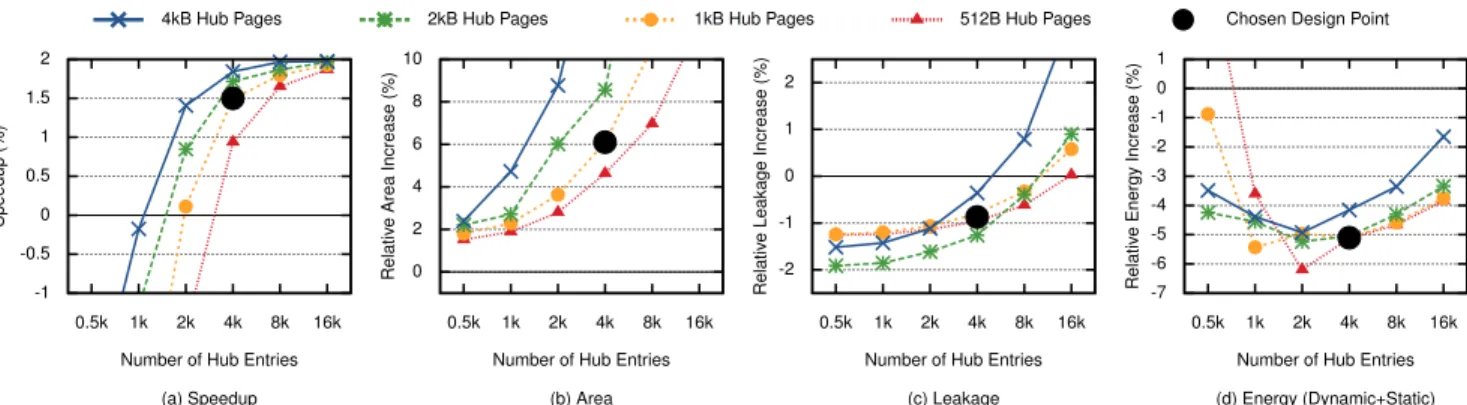
We used the methodology described in Section 4.1 to evalu-ate the performance of this replacement policy. Figure 4 shows the average speedup (a), area increase (b) leakage increase (c) and total D2D energy (d) compared to a standard tag-based cache hierarchy as a function of number of Hub entries. As expected, a larger Hub improves performance. At 16 k Hub entries, the L2 has the same number of cache lines as the Hub has pages, and increasing number of page entries further will not improve the performance. However, such a large Hub pays a high cost in area and leakage. The cache energy (Figure 4d) increases with fewer hub entries due to more leakage from longer execution, whereas more entries run faster but have higher leakage and dynamic energy in the Hub.
In the rest of this paper, we use the 4 k entry, 1 kB micro page Hub design point (the black dot in Figure 4). It requires 6% more area than a tag-based cache hierarchy, but has 1% lower leakage due to fewer high-performance transistors from removing the L1 caches’ tag-arrays. It has an average speedup of 1.5% and reduces the total cache energy by 5.1% compared to a tag-based hierarchy (see “Base” in Table 1). However, if a larger area increase can be tolerated, a 2 k entry Hub with no micro pages would result in similar speedup, leakage, and energy benefits.
3.4. Summary
In the D2D design, a hub eviction requires that the cache flush all data in that page, because we have no tags to track the data without the Hub entry. To minimize the impact if this requirement, we safeguard L1 instructions and data from being evicted due to large data sets by first evicting Hub entries with no eTLB pages, and we use micro pages to minimizing area and leakage as the number of Hub entries is increased in order to satisfy applications with sparse access patterns.
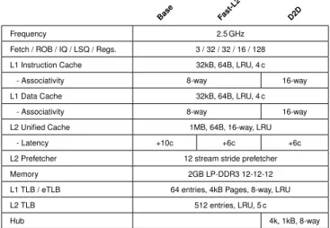
Base Fast-L2 D2D
Frequency 2.5 GHz
Fetch / ROB / IQ / LSQ / Regs. 3 / 32 / 32 / 16 / 128
L1 Instruction Cache 32kB, 64B, LRU, 4 c
- Associativity 8-way 16-way
L1 Data Cache 32kB, 64B, LRU, 4 c
- Associativity 8-way 16-way
L2 Unified Cache 1MB, 64B, 16-way, LRU
- Latency +10c +6c +6c
L2 Prefetcher 12 stream stride prefetcher
Memory 2GB LP-DDR3 12-12-12
L1 TLB / eTLB 64 entries, 4kB Pages, 8-way, LRU
L2 TLB 512 entries, LRU, 5 c
Hub 4k, 1kB, 8-way
Table 1: Processor Configurations.
4. Results
The previous section explored different D2D cache design points, and selected a Hub configuration with 4 k entries and 1 kB micro page with eTLB-aware replacement. In this sec-tion, we compare the energy and performance with a standard tag-based cache hierarchy. We then leverage the shorter L2 latency by shrinking the L1 caches and ROB without hurting performance compared to the baseline.
4.1. Methodology
We use the gem5 x86 full-system simulator [2] to evaluate per-formance. Table 1 shows the selected configurations. We focus on energy-efficient processors and configured the gem5 simu-lator to resemble a contemporary energy-efficient processor such as ARM A15 or Intel Silvermont (Atom). The simulated processor runs at 2.5 GHz, has a 2-level cache hierarchy, and an L2 stride prefetcher.
We use the CACTI 6.5 [13, 11] cache simulator (22 nm pro-cess, one read-write port) to compute access times and energy. The L1I, L1D and TLB/eTLBs use high-performance transis-tors (itrs-hp) and optimize for access time. The L2 cache, L2 TLB and the Hub use low static power transistors (itrs-lstp) and optimize for area and read energy. All data structures hold-ing meta data and their movements are modelled and included in performance and power measurements.
We compare the D2D cache with two standard tag-based configurations: Base and Fast-L2. Base uses a normal L2 cache with 10 cycles latency (4 cycles to access the tags, and 6 cycles to access the data). Fast-L2 uses a faster L2 cache with 6 cycles latency. To achieve a 6 cycles latency, Fast-L2 accesses the L2 tags in parallel with the L2 data. This wastes energy, but removes the tag latency.
Sembrant et al. [15] has already shown that tag-less L1 caches consume substantially less energy that traditional par-allel VIPT caches, due to their ability to identify the way in the L1 cache where the requested data resides. While the
de-0 250 500 750 L1I APKI 0 25 50 75 L2 APKI 0 5 10 15 20
gcc hmmer libquantumper l tpc-c l2 sensitiv e l2 insensitiv e aver age (all) Mem APKI
8 kB L1I/L1D 16 kB L1I/L1D16 kB L1I/L1D 32 kB L1I/L1D
Tot. Accesses Direct Accesses Tot. Accesses Direct Accesses Tot. Accesses Direct Accesses
(a) Instruction Demand Accesses
0 250 500 750 L1D APKI 0 25 50 75 L2 APKI 0 5 10 15 20
gcc hmmer libquantumper l tpc-c l2 sensitiv e l2 insensitiv e aver age (all) Mem APKI
8 kB L1I/L1D 16 kB L1I/L1D16 kB L1I/L1D 32 kB L1I/L1D
Tot. Accesses Direct Accesses Tot. Accesses Direct Accesses Tot. Accesses Direct Accesses
(b) Data Demand Accesses
Figure 6: Accesses per Kilo Instruction (AKPI) to each cache level, and number of times D2D can access the data directly without consulting the Hub.
sign proposed in this paper has the same favorable low-power L1 properties as [15], the goal of this section is to evaluate the savings due to the direct-to-data (D2D) property of the proposed design, i.e., the savings due to the ability to identify the cache level (or memory) where the requested data resides. Thus, the baselines used (Base and Fast-L2) have both been designed using low-power 2-phase L1 cache, where the tag comparison is made before the data lookup to save power. Forthermore, we assume that there is no performance cost for doing so. That way, the energy saving from D2D can be separated from the total energy saving possible compared with a traditional 2-level cache design with a parallel lookup VIPT and and 2-phase L2.
The D2D cache has a 4 k entry Hub, with 1 kB micro-pages. It has a 6 cycles L2 latency, the same L2 latency as Fast-L2, since it does not access any L2 tags. Both baseline configu-rations and D2D have 64 entry TLBs/eTLBs in order to keep the TLB miss ratio the same, and a 512 entry L2 TLB.
The L2 cache is 1 MB and 16-ways associative. The D2D cache must therefore store 4 way index bits for each cache line in the cache line location table (CLT). Since we already have 4 way bits in the CLT for each cache line, we can triv-ially support the same associativity in the L1 caches with no additional cost. The D2D cache therefore also has 16-ways associative L1 caches. Base and Fast-L2’s L1 caches have lower associativity, since increasing the associativity would also increase the L1 tag energy.
To evaluate the D2D cache, we use the SPECcpu-2006 [8] benchmarks with reference inputs, and SPECjbb-2005 [18] and TPC-C [19] (MySQL/InnoDB) to evaluate the D2D cache with benchmarks that have larger instruction footprints. We use 10 uniformly distributed simulation points per benchmark
(570 simulation points in total). For each simulation point the caches are warmed for 100 M instructions before simulating 10 M instructions.
We present gcc, hmmer, libquantum, tpc-c, and perl in more detail since they represent interesting behavior. gcc and hmmer use the L2 cache for data, and libquantum uses it for prefetches, perl and tpc-c use it for instructions.
To isolate the performance impact for those parts of the applications that are sensitive to the L2 latency, we divide the simulation points into two groups: L2 sensitive and L2 insensitive. To find the sensitive simulation points, we com-pared the speedup of Fast-L2 with Base and included only those simulation points that showed more than 5% speedup with the faster L2. The analysis shows that 12 of the bench-mark have L2 sensitive phases, spanning more than 10% of the total execution. The L2 sensitive set shows the average of all benchmarks where only L2 sensitive simulation points are included.
4.2. D2D Cache Effectiveness
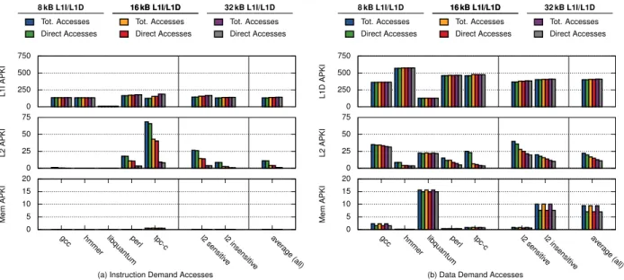
The D2D cache can access each cache level directly by read-ing the cache line’s location information in the eTLB. Fig-ure 6 shows the number of accesses per thousand instructions (APKI) to each cache level (Tot. Accesses), and the number of times that the D2D cache was able to access the data directly (Direct Accesses), for 8, 16, and 32 kB L1I/D caches. Since gem5 caches the last accessed instruction cache line within the fetch unit, we see fewer L1I accesses than L1D accesses.
For D2D to work, it needs a high hit rate in the eTLB. The figure shows that 75.6% of the cache misses, 87.2% of the L2 hits, and 99.7% of the L1 hits are correctly identified by the eTLB lookup with a 32 kB cache without the need to access
the Hub.
D2D sends 75.6% of the cache misses directly to memory, due to spatial locality within each 4 kB eTLB pages. On a compulsory miss, a new entry in the Hub is created and an empty cache-line location table is installed into the eTLB. Succesive misses to the same page can thus be sent directly to memory since D2D knows that the data is not in any cache. This saves energy in lower level caches since the request goes directly to memory, and it lowers memory latency since the request does not have to traverse whole cache hierarchy before being sent off to memory.
4.3. Shrinking the L1 caches
The D2D cache has a lower L2 latency than Base since it ac-cesses the L2 data directly, and can therefore tolerate more L1 misses as long as they hit in the without hurting performance. We use this property to save energy by shrinking both the L1 data cache and the L1 instruction cache.
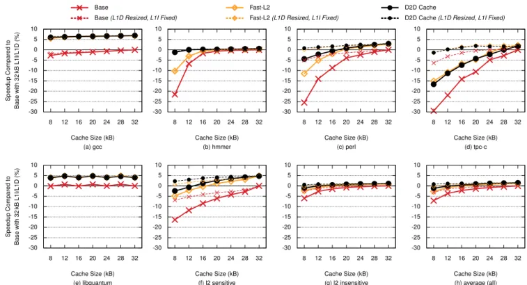
Figure 7 shows the speedup compared to the 32 kB 8-way L1s in Base as a function of cache size. The solid lines shows the speedup when shrinking both the L1I cache size and the L1D cache size, and the dashed lines shows the speedup when shrinking only the L1D cache size. Figure 8 shows the total (static + dynamic) cache hierarchy energy per instruction (i.e., cache energy divided by executed instructions) as a function of cache size when shrinking both the L1I cache size and the L1D cache size. The D2D cache’s different component are shown in different colors, with the L1 caches broken down into static (check) and dynamic (solid) energy.
L2 Data Sensitive (Figures a, b). gcc’s working set does not fit in a 32 kB L1D cache, and thus reducing the L1 caches does not significantly decrease the performance. Fast-L2 and D2D have 40% shorter L2 latency, and we therefore see a nearly constant speedup of about 6% across all cache sizes.
gcc has a high L2 cache usage and spends 43% percent of the cache hierarchy energy in the L2 cache when it has a 32 kB L1. Shrinking the L1 cache down to 8 kB increases the L2 energy by 12% due to more L2 accesses, but saves 61% of the L1 energy. This reduces gcc’s total cache energy by 26% for the D2D cache. Base shows a similar trend, but slows down gcc by 8-6% compared to D2D due to longer L2 latency. Fast-L2 has the same performance as D2D, but consume significantly more energy in the L2 cache since it wastes more L2 energy by reading all the data ways in parallel with the tag lookup.
hmmer’s working set fits in a 16 kB L1D cache and we see no performance degradation from 32 kB to 16 kB. However, L2 usage in Base and Fast-L2’s increases with an L1 smaller than 16 kB. Fast-L2 has a much smaller performance degrada-tion compared to the Base since it can tolerate more L2 traffic due to the faster L2. The D2D cache has the same L2 latency as Fast-L2, but has higher L1 associativity which results in fewer conflict misses and therefore fewer L2 accesses. This results in a 20 percentage points speedup difference compared
to Base at 8 kB (12 due to the faster L2, and 8 due to fewer conflict misses).
hmmer spends 9% of the total cache energy in the L2 cache with a 32 kB L1D since nearly all access hit in the L1 cache. The D2D cache does not increase the L2 traffic. We therefore see a steady decline in energy as the L1 caches shrinks. This saves 39% of the total energy. Both Base and Fast-L2 intro-duce conflict misses at 8 kB and 12 kB, resulting in more L2 traffic and higher energy consumption.
L2 Prefetch Sensitive (Figure e). libquantum has a prefetch-friendly access pattern, enabling most of its working set to be prefetched into the L2. Fast-L2 and D2D improve per-formance since they have lower latency to the prefetched data. This results in a 5 percentage point speedup difference across all cache sizes. This illustrates the benefit of the D2D cache and prefetch-friendly application where a lower L2 latency helps regardless of L1 cache size.
libquantum has a high L2 cache energy usage and low L1 cache usage, since it prefetches into the L2. Shrinking the L1 caches therefore saves L1 energy without increasing the L2 energy.
L2 Instructions Sensitive (Figures c, d). The instruction sets for perl and tpc-c barely fit in a 32 kB L1I cache. We therefore see a steady decrease in performance when the L1I cache shrinks as more instructions are evicted into the L2 cache. Fast-L2 and D2D reduces number of instruction fetch stall cycles for tpc-c by 28.5%. This results in a 15 percentage points speedup at 8 kB. However, all three cache designs see noticeable performance degradation with smaller cache sizes.
The L2 cache energy increases significantly as the L1 caches shrinks, since all the saved L1 energy is traded for L2 energy. We therefore lose energy by shrinking the L1 caches, since to much traffic is moved to the L2 cache.
Averages (Figures f, g, h) across all. D2D speeds up the L2 sensitive phases (f) by 5-14% compared to Base as the L1 cache-sizes shrink, since the L2 sensitive phases’ L2 us-age increases with smaller L1 cache sizes. In contrast, the L2 insensitive phases (g) are not affected by the L2 cache, resulting in approximately the same performance for all three configurations.
Shrinking the L1 caches saves L1 cache energy but more energy is instead expended in the L2 cache. The L2 sensitive phases’ total cache hierarchy energy therefore increases due to high L2 usage. The L2 insensitive phases, on the other hand, have lower L2 usage, resulting in a total cache energy reduc-tion. On average (across all of SPEC, TPC-C, and SPECjbb), D2D expends 5-17% less cache energy compared to Base depending on L1 cache size.
Moreover, D2D can reduce the L1 cache sizes from 32 kB a 12 kB across all benchmarks while maintaining the same performance as Base, thus saving 21% of the total cache en-ergy. Base can also save energy by shrinking the L1 caches, however, its higher L2 latency slows down the execution by 4% on average, and the L2 sensitive phases by 11%.
-30 -25 -20 -15 -10 -5 0 5 10 8 12 16 20 24 28 32 Speedup Compared to Base with 32 kB L1I/L1D (% ) Cache Size (kB) (a) gcc -30 -25 -20 -15 -10 -5 0 5 10 8 12 16 20 24 28 32 Cache Size (kB) (b) hmmer -30 -25 -20 -15 -10 -5 0 5 10 8 12 16 20 24 28 32 Cache Size (kB) (c) perl -30 -25 -20 -15 -10 -5 0 5 10 8 12 16 20 24 28 32 Cache Size (kB) (d) tpc-c -30 -25 -20 -15 -10 -5 0 5 10 8 12 16 20 24 28 32 Speedup Compared to Base with 32 kB L1I/L1D (% ) Cache Size (kB) (e) libquantum -30 -25 -20 -15 -10 -5 0 5 10 8 12 16 20 24 28 32 Cache Size (kB) (f) l2 sensitive -30 -25 -20 -15 -10 -5 0 5 10 8 12 16 20 24 28 32 Cache Size (kB) (g) l2 insensitive -30 -25 -20 -15 -10 -5 0 5 10 8 12 16 20 24 28 32 Cache Size (kB) (h) average (all) Base
Base(L1D Resized, L1I Fixed)
Fast-L2
Fast-L2(L1D Resized, L1I Fixed)
D2D Cache
D2D Cache(L1D Resized, L1I Fixed)
Figure 7: D2D cache speedup as a function of L1I/L1D cache size.
Energy per Instr uction (pJ) Cache Size (kB) (a) gcc Cache Size (kB) (b) hmmer Cache Size (kB) (c) perl Cache Size (kB) (d) tpc-c Energy per Instr uction (pJ) Cache Size (kB) (e) libquantum Cache Size (kB) (f) l2 sensitive Cache Size (kB) (g) l2 insensitive Cache Size (kB) (h) average (all) 0 5 10 15 20 25 30 35 8 12 16 20 24 28 32 0 5 10 15 20 25 30 35 8 12 16 20 24 28 32 0 5 10 15 20 25 30 35 8 12 16 20 24 28 32 0 5 10 15 20 25 30 35 8 12 16 20 24 28 32 0 5 10 15 20 25 30 35 8 12 16 20 24 28 32 0 5 10 15 20 25 30 35 8 12 16 20 24 28 32 0 5 10 15 20 25 30 35 8 12 16 20 24 28 32 0 5 10 15 20 25 30 35 8 12 16 20 24 28 32
Tot. Base Tot. Fast-L2 Tot. D2D Cache
L1I eTLB L1I S/D L1D eTLB L1D S/D Hub L2
-30 -25 -20 -15 -10 -5 0 5 10 16 20 24 28 32 36 40 Speedup Compared to Base with 32 entr y R OB (%) ROB Size (a) gcc -30 -25 -20 -15 -10 -5 0 5 10 16 20 24 28 32 36 40 ROB Size (b) hmmer -30 -25 -20 -15 -10 -5 0 5 10 16 20 24 28 32 36 40 ROB Size (c) perl -30 -25 -20 -15 -10 -5 0 5 10 16 20 24 28 32 36 40 ROB Size (d) tpc-c -30 -25 -20 -15 -10 -5 0 5 10 16 20 24 28 32 36 40 Speedup Compared to Base with 32 entr y R OB (%) ROB Size (e) libquantum -30 -25 -20 -15 -10 -5 0 5 10 16 20 24 28 32 36 40 ROB Size (f) l2 sensitive -30 -25 -20 -15 -10 -5 0 5 10 16 20 24 28 32 36 40 ROB Size (g) l2 insensitive -30 -25 -20 -15 -10 -5 0 5 10 16 20 24 28 32 36 40 ROB Size (h) average (all) 8 kB L1D D2D Cache 8 kB L1D Base-SlowL2 16 kB L1D D2D Cache 16 kB L1D Base-SlowL2 32 kB L1D D2D Cache 32 kB L1D Base-SlowL2
Figure 9: D2D cache speedup as a function of ROB size. Summary
We compared three different cache hierarchies’ energy and performance. Fast-L2 has better performance than Base due to faster L2, but suffers in energy since the faster L2 consume more energy. The D2D cache is faster and consumes less energy than both Base and Fast-L2. This enable us to shrink the L1 caches without hurting performance.
4.4. Shrinking the Reorder Buffer Size
Aside from shrinking the L1 cache size, a shorter L2 latency also makes it possible to shrink the reorder buffer (ROB) size for L2 latency-bound applications since the ROB does not have to hide as much cache latency.
Figure 9 shows the speedup compared to a 32 kB Base with a 32 entry ROB as a function of ROB size. The thinner dashed lines show the speedup as a function of L1D cache size, but with L1I fixed to 32 kB. The L2 latency-bound (a, e, f) show that the ROB size can be reduced without hurting performance with D2D. For example, a D2D cache with a 24 entry ROB has the same performance as Base with a 32 entries ROB for the L2 sensitive parts of the application (f). The ROB can therefore be reduce by 25% without hurting performance.
5. Related Work
In this section we look at four areas of related work (coarse-grained tracking, extended TLBs, way-prediction, and NUCA caches).
Coarse-grained tracking.Zebchuk et al. [20] use coarse-grained cache line tracking in the L2 and last-level caches to re-duce tag-area, eliminate snoops, and prefetching. Seznec [16] uses pointers to reduce tag storage by replacing the page num-ber in the tags with a pointer to the page in a page numnum-ber cache. This reduces the tag storage since the pointer is much smaller than the page number. However, both still use tag-based L1 caches. The L2 latency will therefore not improve since the L2 cache line location must be looked up in the L2 cache before the data can be accessed. D2D instead tracks the cache line location across the L1 and L2, and can therefore access the L2 cache line directly.
Extended TLB (eTLB). Hagersten et al. [6], Boettcher et al. [3] and Sembrant et al. [15] extend the TLB with cache-line way information to reduce L1 cache energy. Hagersten et al. [6] and Boettcher et al. [3] keep the tag array and treat the TLB way information as hints, whereas Sembrant et al. [15] provide accurate tracking and can therefore eliminate the tag array. Sembrant et al. [15] need reverse address translations to handle coherency and synonyms due to virtual indexing. D2D avoids virtual addressing problems by using a physically indexed Hub to connect the virtual and physical address domains. None of these works address L2 latency since they only track L1 cache line locations.
Way-prediction. Way-prediction is used to predict in which way a cache line is located [4, 21, 14, 9]. Typically this is done per cache level, but can be extended to span
dif-ferent levels of the cache hierarchy. Min et al. [12] store L2 way information in a location cache that is accessed in parallel with the L1 cache. On a location table hit, the right L2 loca-tion is read. However, this requires a large predicloca-tion table to cover the L2’s capacity, and it wastes energy on L1 cache hits since a prediction is made on every access. The D2D cache knows where the cache line is located, and only access the right cache without relying on predictions. To reduce the eTLB energy, Sembrant et al. [15] propose page-prediction to predict in which way a page is located in the eTLB.
NUCA caches.NUCA caches have been proposed as a way to deal with growing wire delays in large last level caches [10, 5, 1, 7]. To optimize for the different access latencies, several policies have been suggested in order to migrate data closer to where it is needed. These works are orthogonal to D2D cache, since a tag-based NUCA L3 cache can easily be placed between the L2 and memory. The eTLB or the Hub can then be used to assist the placement policies.
6. Conclusions
In this paper, we presented the Direct-to-Data (D2D) cache. It extends the TLB with cache line location information indi-cating in which cache level and way the cache line is located. This enables the D2D cache to 1) skip levels in the cache hier-archy on lookups, 2) eliminate tag-arrays, and 3) go directly to DRAM on cache misses. This speeds up L2 sensitive appli-cations’ performance by 5-14% by reducing the L2 latency by 40% and it saves 5-17% of the total cache hierarchy energy by only reading the right level and way directly.
We explored different design points and replacement poli-cies in order to minimize number of cache line evictions due to Hub replacement, and to safeguard L1 instructions and data from early eviction due to large data sets.
We further showed that we can trade off the improved L2 latency to reduce 1) the reorder buffer size and 2) the L1 cache size. This saved 21% cache energy across all benchmarks without hurting performance.
7. Acknowledgments
This work was financed by the CoDeR-MP project and the UPMARC research center. Simulations were performed on resources provided by the Swedish National Infrastructure for Computing (SNIC) at Uppsala Multidisciplinary Center for Advanced Computational Science (UPPMAX).
References
[1] B. M. Beckmann and D. A. Wood, “Managing Wire Delay in Large Chip-Multiprocessor Caches,” inProc. International Symposium on Microarchitecture (MICRO), 2004.
[2] N. Binkert, B. Beckmann, G. Black, S. K. Reinhardt, A. Saidi, A. Basu, J. Hestness, D. R. Hower, T. Krishna, S. Sardashti, R. Sen, K. Sewell, M. Shoaib, N. Vaish, M. D. Hill, and D. A. Wood, “The gem5 Simula-tor,”SIGARCH Comput. Archit. News, 2011.
[3] M. Boettcher, G. Gabrielli, B. M. Al-Hashimi, and D. Kershaw, “MALEC: A Multiple Access Low Energy Cache,” inProc. Design, Automation Test in Europe Conference Exhibition (DATE), 2013. [4] B. Calder, D. Grunwald, and J. Emer, “Predictive Sequential
Associa-tive Cache,” inProc. International Symposium on High-Performance Computer Architecture (HPCA), 1996.
[5] Z. Chishti, M. D. Powell, and T. N. Vijaykumar, “Distance Asso-ciativity for High-Performance Energy-Efficient Non-Uniform Cache Architectures,” inProc. International Symposium on Microarchitecture (MICRO), 2003.
[6] E. Hagersten and A. Singhal, “Method and Apparatus for Selecting a Way of a Multi-way Associative Cache by Storing Waylets in a Translation Structure,” Patent US 5 778 427, July, 1998.
[7] N. Hardavellas, M. Ferdman, B. Falsafi, and A. Ailamaki, “Reactive NUCA: Near-optimal Block Placement and Replication in Distributed Caches,” inProc. International Symposium on Computer Architecture (ISCA), 2009.
[8] J. L. Henning, “SPEC CPU2006 Benchmark Descriptions,”SIGARCH Comput. Archit. News, 2006.
[9] S. Kaxiras and M. Martonosi,Computer Architecture Techniques for Power-Efficiency, 2008.
[10] C. Kim, D. Burger, and S. W. Keckler, “An adaptive, non-uniform cache structure for wire-delay dominated on-chip caches,” inProc. Internationl Conference on Architectural Support for Programming Languages and Operating Systems (ASPLOS), 2002.
[11] S. Li, J. H. Ahn, R. D. Strong, J. B. Brockman, D. M. Tullsen, and N. P. Jouppi, “McPAT: An Integrated Power, Area, and Timing Model-ing Framework for Multicore and Manycore Architectures,” inProc. International Symposium on Microarchitecture (MICRO), 2009. [12] R. Min, W.-B. Jone, and Y. Hu, “Location Cache: A Low-Power
L2 Cache System,” inProc. International Symposium on Low Power Electronics and Design (ISPLED), 2004.
[13] N. Muralimanohar, R. Balasubramonian, and N. P. Jouppi, “CACTI 6.0: A Tool to Model Large Caches,” Hewlett Packard Labs, Tech. Rep., 2009.
[14] M. D. Powell, A. Agarwal, T. N. Vijaykumar, B. Falsafi, and K. Roy, “Reducing Set-Associative Cache Energy via Way-Prediction and Selec-tive Direct-Mapping,” inProc. International Symposium on Microar-chitecture (MICRO), 2001.
[15] A. Sembrant, E. Hagersten, and D. Black-Schaffer, “TLC: A Tag-Less Cache for Reducing Dynamic First Level Cache Energy,” inProc. International Symposium on Microarchitecture (MICRO), 2013. [16] A. Seznec, “Don’T Use the Page Number, but a Pointer to It,” inProc.
International Symposium on Computer Architecture (ISCA), 1996. [17] A. Sodani, “Race to Exascale: Opportunities and Challenges,” in
MICRO 2011 Keynote, 2011.
[18] SPECjbb2005,http://www.spec.org/jbb2005/.
[19] Transaction Processing Performance Council,http://www.tpc.org/. [20] J. Zebchuk, E. Safi, and A. Moshovos, “A Framework for
Coarse-Grain Optimizations in the On-Chip Memory Hierarchy,” inProc. International Symposium on Microarchitecture (MICRO), 2007. [21] C. Zhang, X. Zhang, and Y. Yan, “Two Fast and High-Associativity