in Semiconductor Manufacturing Systems
Michael Lifshits, Roman Goldenberg, Ehud Rivlin, and Michael RudzskyTechnion, Computer Science Department, Haifa, Israel.
{protezhe,romang,ehudr,rudzsky}@cs.technion.ac.il
Abstract. In this paper we present a new method for self-localization on wafers using geometric hashing. The proposed technique is robust to image changes induced by process variations, as opposed to the tradi-tional, correlation based methods. Moreover, it eliminates the need in training on reference patterns. Two enhancements are introduced to the basic geometric hashing scheme improving its performance and reliabil-ity: using quadtree for efficient data access and optimal rehashing for Bayesian voting. The approach proved to be highly reliable when tested on real wafer images.
1
Introduction
As computational power has increased over the past decade, machine vision systems have become far more capable than before. In semiconductor industry, where highest levels of precision and robustness are required, they evolved to become a mainstream automation tool enabling computers to replace human vision and guide robotic handling, assembly, and inspection processes. Various semiconductor manufacturing equipment require precise self-localization, so that operations such as lithography, cutting and inspection can be performed to ex-tremely tight tolerances. That is why self-localization on wafers has emerged as a very important task.
There is a demand from machine vision tools to become more adaptive to in-process variations and allow location of reference patterns despite changes in visual appearance occurring during the manufacturing process. Such changes may include non-linear contrast variation, color inversion, re-scaling, rotations and partial pattern obliteration [7].
Traditional tools, found in most commercial packages today, adopt normal-ized grayscale correlation (NGC) which is adequate for locating patterns under ideal conditions, but cannot cope with pattern appearance changes at run-time. Correlation scores are sensitive to degraded images and exhibit low tolerance to image changes in scale, angle, obliteration and contrast variation. Some ven-dors are recently proposing different techniques for self-localization to counteract such negative effects. For example, PatMax software from Cognex applies geo-metric feature analysis to find patterns on the wafer. Individual key features are first found, so that attributes such as shape, angles, arcs and shading can
C.E. Rasmussen et al. (Eds.): DAGM 2004, LNCS 3175, pp. 520–527, 2004. c
be used to achieve invariant matching. Stemmer Imaging utilizes different tools, such as Support Vector Machines (SVM), neural networks, and optimized Hough transform, besides NGC, to accomplish invariant pattern recognition. All these approaches somewhat limited, as they build upon training on particular, prede-fined feature (known as an “acquisition target”) printed at certain position on a wafer. During online self-localization this feature must appear in the field of view of the tool (it might be transformed though). Straightforward comparing current query image with all feasible features is unrealistic.
In this paper we propose a method for self-localization on wafers. It estab-lishes a correspondence between the pattern currently observed in the field of view of the imaging tool and the previously constructed wafer map. It is fast enough for inline microscopy, robust to process variations and does not require training on the acquisition targets. The method is based on geometric hashing [2,4,5,6], a well known pattern recognition algorithm. Tests performed on real wafer images demonstrate the high reliability of the suggested approach.
2
Self-Localization as Pattern Recognition Task
Pattern recognition is a process of identifying objects from perceptual data. Recognition is achieved by finding the correspondence between a given pattern and a set of predefined patterns. In the model-based PR approach, the predefined patterns are described in terms of various properties, such as shape, color, etc. These descriptions are referred to as “models”. A query pattern is then matched to one of those models.
Localization on the wafer is defined in the following manner: given an “eye point” (e.g. partial image of the wafer) estimate its exact position on the wafer map. Therefore, map-based self-localization can be interpreted as model-based pattern recognition as follows. First the wafer map is constructed from partial images captured by a microscope imaging system moving over the wafer sur-face. A possible alternative is to use wafer layout file specifying its geometric structure. Wafer map can be divided into many adjacent parts to be identified during localization. These parts correspond to models in pattern recognition framework, whereas the eye-point plays a role of a query pattern. Matching the current eye-point to one of the previously prepared parts of the wafer map dur-ing localization is essentially the same, as associatdur-ing a query pattern to one of the predefined models in pattern recognition. An example of the wafer eye-point and the corresponding part of the wafer map is shown in Figure 1.
To cope with the enormous amount of geometric structures contained in wafer images, we choose to address the problem of self-localization using geometric hashing. Matching between query eye-point and wafer map is achieved by spatial correspondence of geometric features extracted from the images. These features are used to compose invariant model representations, stored in a database during the offline preprocessing stage of the algorithm. When analyzing the eye-point during localization, the same invariant representation is used as an indexing key to access the hash table and vote for the possible model matches. The model
Part of wafer "map" eye−point
Fig. 1.Example of the eye-point within a wafer map
Winning model eye−point
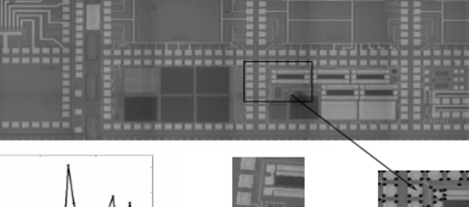
Fig. 2.Outline of the localization process. A wafer map that is constructed from 40 model images is shown on the top. Voting results for the eye-point shown in the middle are plotted on the left. The enlarged image of the winning model (25) with its feature points marked with black dots is presented on the right.
accumulating a significant number of votes indicates the correspondence of cur-rent eye-point with that model. An example of a typical localization process is presented in Fig. 2. This scheme provides low online complexity which deter-mines the actual localization time. It linearly depends on the number of features contained in the eye-point and independent of the number of models stored in the system. This allows to perform a fast localization even on very large scale maps.
The localization algorithm is completed by verification. Given a set of candi-date models that accumulated the highest number of votes, one has to determine which is the best match to the query eye-point. The eye-point is characterized in terms of a feature points set{xi}inP2, and each of the candidate matching mod-els likewise described by its feature points{xi}. First, it is essential to find all
xi↔xi point correspondences to compute a similarity transformation H which transforms a model to the eye-point: Hxi=xi for eachi. Two correspondences are enough to compute H, however, since the points in the query eye-point are measured inexactly (due to noise), all of the correspondences should be used to determine the “best” transformation given the data. Every true correspondence gives rise to two independent equations in the entries of H, while the outliers are
(a) Eye-point feature points (b) Voronoi tessellation (c) Voronoi diagram
Fig. 3.The process of constructing the Voronoi tessellation of the eye-point for verifi-cation acceleration.
robustly eliminated by the RANSAC algorithm. Then H is calculated by finding the least-squares solution of the over-determined linear system.
An important issue is how to efficiently find all of the correspondences. The voting stage of the algorithm provides one corresponding basis (two point-to-point correspondences) between the candidate model and the eye-point-to-point. This allows us to approximate the desired transformation HSby HS and then, after
applyingHSon the candidate model, every model pointHSxiwill correspond to
the closest eye-point featurexi.
Thus, to compute all of the point correspondences it is possible to check the distance of each point xi to every transformed model pointHxi. If the model containsmpoints and the eye-point containsnpoints, those inter-set distances are computed inO(m n) time. This computation can be accelerated by employ-ing aVoronoi tessellation [3] for segmentation of the eye-point image. Voronoi tessellation is partitioning of a plane withnpoints intonconvex polygons such that each polygon contains exactly one point and every point in a given polygon is closer to its central point than to any other. We start the verification by con-structing the Voronoi tessellation from the points in the query eye-point, which is done in O(nlog(n)) time [3] (see Fig. 3). This allows us to find the corre-sponding point ofxiinO(log(n)) by checking what polygon within the Voronoi tessellation contains the transformed point Hxi and choosing its center point. It follows that the time needed for point correspondences calculation is reduced
fromO(m n) toO(m log(n)).
3
Algorithm Performance Enhancements
In this section we suggest two enhancements to the basic method improving its performance and reliability. They address the most problematic issues of the pro-posed localization method (as well as the general geometric hashing technique), which are the performance degradation in presence of noise and non-uniform occupancy of hash bins.
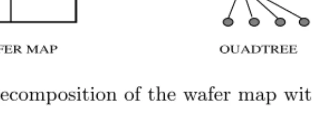
WAFER MAP QUADTREE Whole Image
Quadrants
Fig. 4.Decomposition of the wafer map with quadtree.
3.1 Quadtree
Unlike the absolute localization on the wafer, in the incremental localization discussed here, the initial position is assumed to be known approximately at the beginning of the localization session. The goal is then to refine the eye-point position estimation. Thus, it is possible to search for the eye-eye-point only in relatively small “expectation region” on the wafer map, based on the known initial location. One can observe that in the case of localization on the wafer the set of models is actually formed from the neighboring wafer image tiles. This allows us to refine the basic algorithm using thequadtree- a technique for encoding an image as a tree structure (Figure 4).
The root node represents the entire image; its children represent the four quadrants of the entire image; their children represent the sixteen sub-quadrants, and so on.
Basic algorithm uses 2D hash table, while its bins are accessed according to the computed invariant coordinates. Multiple entries within single bin are organized in a linked list and retrieved altogether when the corresponding bin is accessed. The proposed enhancement replaces the linked list with a quadtree at each bin in the hash table. These trees correspond to the space partitioning of the global wafer map. This way it is possible to access only the relevant part of each tree during voting and thus, exclusively count for models from the “expectation region”. To put it differently, the quadtree allows to select any partial wafer area to be searched for the query eye-point. Practically, the quadtree approach reduces the number of irrelevant entries accessed in a hash table, without actually removing any contained data.
3.2 Rehashing for Bayesian Voting
Ideally, for every feature point of the query eye-point image there is a single model point in the corresponding hash table bin. In practice, features generated by other models can fall into the same bin or even coincide. To deal with this problem one may suggest to reduce the bin size. Unfortunately, the feature points are non-uniformly distributed over the hash table. Therefore, for any bin size there will be either overpopulated or empty bins. It is generally proposed to use rehashing to deal with the problem of non-uniform occupancy of hash bins [8].
Another problem is that the uncertainty in feature point position caused by image noise, shifts it away from the corresponding model feature. This can be
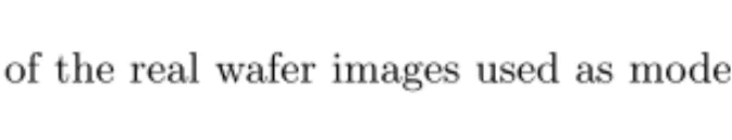
Fig. 5.Examples of the real wafer images used as models in the algorithm.
solved by looking for the matching model feature in a certain, error dependent, neighborhood of the eye-point feature - voting region (see for example Bayesian approach in [9]).
To combine and take the best from both approaches we propose to use a scheme that equalizes voting regions rather then feature density, as suggested before. This is achieved by re-mapping the hash entries using the mapping T : (u, v)→(u, v), such that
u= √π2
r+e2ln(1 +r)
v = arctan(vu) ,
where r = √u2+v2. The detailed derivation and the theoretical basis of the
scheme is reported elsewhere [1]. This allows to improve localization (as well as general geometric hashing) computational performance by minimizing the hash table size and the number of bins accessed, while maintaining optimal recognition rate. Alternatively, the proposed scheme can be used in classical single bin voting to improve recognition rate.
4
Experimental Results
In this section we demonstrate the capabilities of the proposed localization algo-rithm and provide a systematic evaluation of its performance and effectiveness. We performed tests on real wafer images obtained on KLA-Tencor 5200XP over-lay metrology tool using 750 micron field of view. These images were used to construct a map covering an area of 2.25x12.75 millimeters on the wafer surface. Examples with enlarged partial images after preprocessing and corner detection are shown in Figure 5. There are two sequential stages involved in the localiza-tion algorithm: indexing based voting and candidates verificalocaliza-tion. During voting, eye-point invariant description is calculated and used to index into the hash ta-ble and vote for all the accessed entries. This description is based on a pair of features, a basis, see [6]. In many practical situations, there is a good chance that one of the points used to form a basis was reported by mistake and does not match any model point. Therefore, one should make multiple attempts us-ing different bases (e.g. different descriptions), to ensure with sufficiently high probability that at least one of them is free of outliers. We evaluate the localiza-tion algorithm performance by varying the number of different eye-point feature bases being used in voting.
1 2 3 4 5 0 0.1 0.2 0.3 0.4 0.5 0.6 0.7 0.8 0.9 1 Number of bases Localization results hit rate false alarm rate miss rate
Fig. 6.System behavior with different number of bases being used in voting.
We tested the algorithm on a total of 104different localization tasks to obtain
a statistically meaningful measure of its performance. Each time we select a random eye-point and then, if correct location on the wafer “map” is reported by the algorithm (ground truth was available due to the nature of data set formation), the result is considered to be true positive (TP). In case of incorrect or no location (simply because none of the database models got enough votes), the result is regarded as a false positive (FP) or miss accordingly.
The summary of the obtained results is presented in Figure 6. Hit rate
HR = TestsTP reaches 95% with 4% false alarm rate and 1% miss rate when 4
bases are being used. The inaccuracy of the localization result may be formu-lated as follows. Assuming the eye-point features are measured with Gaussian error of standard deviation σ, it can be shown that the RMS distance of the estimated point location from its true value isσ(d/2n)1/2, wherenis number of correspondences used andd is the number of transformation parameters. Thus substituting d = 4 for similarity, and taking 50 sample points, results in the estimation error of 0.2 pixels. If the eye-point image of size 200x200 pixels is taken at resolution of 50 micron we come up with the localization accuracy of 50 nanometer.
HR of 100% is not achieved as the constructed map contains areas difficult for localization: having no distinguishable features or filled with repetitive ge-ometric structures. Note that even a human would have serious difficulties in solving the task of self-localization for “degenerate” eye-points selected from these unfavorable areas. Generally, we found that the algorithm performed well for eye-points from most of the wafer areas.
5
Summary
We presented a new method for self-localization on wafers, based on the geomet-ric hashing technique. The method is invariant to changes in visual appearance, such as non-linear contrast variation, scale, rotation and partial obliteration.
Two enhancements were proposed to the basic geometric hashing algorithm, im-proving its computational performance by optimally distributing the entries over the hash table and allowing an efficient access to the table entries. We showed how a verification can be significantly accelerated by applying a voronoi tessel-lation of the eye-point. Extensive experimental analysis demonstrate the high reliability of the proposed method.
Acknowledgement. This work was conducted as part of the Wafer Fab Cluster Management (WFCM) Consortium supported by the ”MAGNET” program of the Chief Scientist Office at the Israeli Ministry of Industry and Trade.
References
1. I. Blayvas, R. Goldenberg, M. Lifshits, E. Rivlin, and M. Rudzsky, Geometric hashing: Rehashing for bayesian voting, Accepted toInternational Conference of Pattern Recognition, 2004.
2. A. Kalvin, E. Schonberg, J. T. Schwartz, M. Sharir, Two-dimensional, model-based, boundary matching using footprints, International Journal of Robotics Research, vol. 5, no. 4, pp. 38–55, 1986.
3. M. V. Kreveld, M. Overmars, O. Schwarzkopf, and M. V. K. Mark de Berg, Com-putational Geometry, 2nd ed. Berlin: Springer Verlag, 2000, ch. Voronoi Diagrams: The Post Office Problem, pp. 147–163.
4. Y. Lamdan, J. T. Schwartz, and H. J. Wolfson, Object recognition by affine invari-ant matching, Proc.IEEE Conference on Computer Vision and Pattern Recogni-tion, USA, pp. 335–44, June 1988.
5. Y. Lamdan, J. T. Schwartz, and H. J. Wolfson, Affine invariant model-based object recognition,IEEE Transactions on Robotics and Automation, vol. 6, no. 5, pp. 578– 589, 1990.
6. Y. Lamdan, and H. J. Wolfson, Geometric hashing: A general and efficient model-based recognition scheme, Proc.2nd International Conference on Computer Vi-sion, USA, pp. 238–49, June 1988.
7. S. Melikian, Geometric searching improves machine vision,Lasers and Optronics, vol. 18, no. 7, pp. 13, 1999.
8. I. Rigoutsos, and R. Hummel, Several results on affine invariant geometric hashing, Proc.8th Israeli Conference on Artificial Intelligence and Computer Vision, Israel, December 1991.
9. I. Rigoutsos, and R. Hummel, A bayesian approach to model matching with ge-ometric hashing,Computer Vision and Image Understanding, vol. 62, no. 1, pp. 11–26, 1995.