Experimental and numerical study of pressure drop and
heat transfer in a single-phase micro-channel heat sink
Weilin Qu, Issam Mudawar
*Boiling and Two-phase Flow Laboratory, School of Mechanical Engineering, 1288 Mechanical Engineering Building, Purdue University, West Lafayette, IN 47907-1288, USA
Received 6July 2001; received in revised form 26October 2001
Abstract
The pressure drop and heat transfer characteristics of a single-phase micro-channel heat sink were investigated both experimentally and numerically. The heat sink was fabricated from oxygen-free copper and fitted with a polycarbonate plastic cover plate. The heat sink consisted of an array of rectangular micro-channels 231lm wide and 713lm deep. Deionized water was employed as the cooling liquid and two heat flux levels,q00
eff¼100 W=cm 2 andq00 eff¼200 W=cm 2 , defined relative to the planform area of the heat sink, were tested. The Reynolds number ranged from 139 to 1672 for
q00 eff¼100 W=cm 2 , and 385 to 1289 forq00 eff¼200 W=cm 2
. The three-dimensional heat transfer characteristics of the heat sink were analyzed numerically by solving the conjugate heat transfer problem involving simultaneous determi-nation of the temperature field in both the solid and liquid regions. Also presented and discussed is a detailed de-scription of the local and average heat transfer characteristics of the heat sink. The measured pressure drop and temperature distributions show good agreement with the corresponding numerical predictions. These findings dem-onstrate that the conventional Navier–Stokes and energy equations can adequately predict the fluid flow and heat transfer characteristics of micro-channel heat sinks. Ó 2002 Elsevier Science Ltd. All rights reserved.
1. Introduction
Micro-channel heat sinks constitute an innovative cooling technology for the removal of a large amount of heat from a small area. The heat sink is usually made from a high thermal conductivity solid such as silicon or copper with the micro-channels fabricated into its sur-face by either precision machining or micro-fabrication technology. These micro-channels have characteristic dimensions ranging from 10 to 1000lm, and serve as flow passages for the cooling liquid. Micro-channel heat sinks combine the attributes of very high surface area to volume ratio, large convective heat transfer coefficient, small mass and volume, and small coolant inventory. These attributes render these heat sinks very suitable for cooling such devices as high-performance
microproces-sors, laser diode arrays, radars, and high-energy-laser mirrors.
The micro-channel heat sink cooling concept was first introduced by Tuckerman and Pease in the early 1980s [1]. They fabricated a rectangular micro-channel heat sink in a 11 cm2silicon wafer. The channels had
a width of 50lm and a depth of 302lm, and were separated by 50 lm thick walls. Using water as cooling fluid, the micro-channel heat sink was capable of dissi-pating 790 W=cm2 with a maximum substrate temper-ature raise of 71 °C above the water inlet temperature and a pressure drop of 2.2 bar (31 psi).
Due to their inherent advantages, micro-channel heat sinks have received considerable attention since Tuck-erman and Pease’s pioneering study. Several studies have since been published which can be grouped as an-alytical [2–8], numerical [9,10], or experimental [11–20]. The primary objective of most of the analytical studies is to develop design schemes which can be used to optimize the dimensions of the heat sink. This is typically accomplished by minimizing the overall ther-mal resistance of the heat sink for a given pressure drop. www.elsevier.com/locate/ijhmt
*Corresponding author. Tel.: 494-5705; fax: +1-765-494-0539.
E-mail address:mudawar@ecn.purdue.edu (I. Mudawar).
0017-9310/02/$ - see front matterÓ 2002 Elsevier Science Ltd. All rights reserved. PII: S 0 0 1 7 - 9 3 1 0 ( 0 1 ) 0 0 3 3 7 - 4
Among others, Knight et al. [5,6] presented an optimi-zation scheme that included both laminar and turbulent flow. Their results indicated that when the pressure drop is small, laminar flow prevails, yielding low thermal re-sistance. Conversely, when the pressure drop is large, the optimal thermal resistance is found in the turbulent re-gion.
To develop such an optimization design scheme, it is essential to have an analytical description of the trans-port processes in the heat sink. Heat transfer in the micro-channel is a conjugate one, combining heat con-duction in the solid and convection to the cooling fluid. Due to the complicated nature of this flow, it is impos-sible to develop a comprehensive analytical solution for the governing differential equations. Therefore, most analytical studies adopt the classical fin analysis method, which models the solid walls separating micro-channels
as thin fins, and simplifies the heat transfer process by introducing such major approximations as one-dimen-sional heat transfer, constant convective heat transfer coefficient, and uniform fluid temperature. While the classical fin analysis method provides a simple method to describing the heat transfer performance of a micro-channel heat sink, its accuracy can be greatly compro-mised by its simplifying assumptions.
A more accurate description of the fluid flow and heat transfer characteristics of a micro-channel heat sink necessitates the use of direct numerical simulation methods. Wesberg et al. [9] performed a two-dimen-sional numerical analysis by assuming both hydrauli-cally and thermally fully developed flow within the micro-channels. Fedorov and Viskanta [10] developed a three-dimensional model by eliminating the approxi-mation of fully developed flow, accounting for devel-Nomenclature
Abot area of unit cell bottom wall occupied
by copper
Ac cross-sectional area of channel
At area of overall heat sink top surface
cp specific heat at constant pressure
dh hydraulic diameter of channel, four
times ratio of cross-sectional area to wetted perimeter
hconv natural convection heat transfer
coefficient
H height of unit cell
Hch height of channel
Hw1 thickness of cover plate
Hw2 thickness from unit cell bottom wall to
channel bottom wall
i number of iteration
k thermal conductivity
Kc1;Kc2 contraction loss coefficient
Ke1;Ke2 expansion loss coefficient L length of unit cell
L1;L2;L3;L4 distance between thermocouple holes n outer normal coordinate at interface
between solid and liquid
N number of channels in heat sink
Nu Nusselt number
P pressure
Pw power supplied to micro-channel heat
sink
DP total pressure drop
DPch pressure drop along micro-channels
DPc1;DPc2 contraction pressure loss
DPe1;DPe2 expansion pressure loss
q00 heat flux
q00
bot heat flux at unit cell bottom wall
occupied by copper
q00
eff effective heat flux based on planform
area of heat sink top surface
Re Reynolds number
T temperature
Tin fluid inlet temperature
Tm fluid bulk temperature
T1 ambient temperature
u velocity component inxdirection
uin fluid inlet velocity
uout fluid outlet velocity
v velocity component inydirection ~
V
V velocity vector _
V
V volume flow rate
w velocity component inzdirection
W width of unit cell
Wch width of channel
Ww half-width of wall separating channels x Cartesian coordinate y Cartesian coordinate z Cartesian coordinate Greek symbols l dynamic viscosity q density Subscripts av average f fluid in inlet out outlet p1 deep plenum p2 shallow plenum s solid
opment of both the velocity and temperature fields. No detailed comparison between the experimental results and numerical predictions was provided in these studies to validate the numerical analysis.
In addition to the above-mentioned analytical and numerical studies, several experimental studies can be found in the literature. Micro-channel heat sinks with different materials, dimensions, and cooling fluids were fabricated and tested. An excellent review of the exper-imental studies in the 1980s was provided by Phillips [4]. More recent experimental investigations were conducted by Ravigururajan et al. [16], Harms et al. [17,19], Rah-man and Gui [14,15], RahRah-man [20], and Kawamo et al. [18]. Ravigururajan et al. [16] tested a copper micro-channel heat sink with 270lm wide and 1000lm deep micro-channels. The overall heat sink was 2.25 cm long and 2.42 cm wide. Results for Refrigerant-124 showed the heat transfer coefficient increased between 300% and 900% compared with the theoretical value for laminar flow based on a Nusselt number of 4.36. They attributed this enhancement to thinning of the boundary layer in the narrow channels. Rahman and Gui [14] tested three micro-channel heat sinks fabricated in silicon wafers. The micro-channels were 1.0 mm wide and 221, 254, 278lm in depth, and the overall heat sink was 4.8 cm long and 4.6cm wide. Measured values of the average Nusselt number for water were larger than predicted analytically for developing laminar flow. This enhance-ment was attributed to breakage of the velocity boundary layer by micro-surface roughness. The tran-sition from laminar to turbulent flow was somewhat gradual because the small channel dimension was of the same order of magnitude as the length scale of turbulent eddies. Harms et al. [17] tested a 2.5 cm long, 2.5 cm wide silicon heat sink having 251lm wide and 1030lm deep micro-channels. A relatively low Reynolds number
of 1500 marked transition from laminar to turbulent flow, which was attributed to a sharp inlet, relatively long entrance region, and channel surface roughness. They concluded the classical relation for local Nusselt number was fairly accurate for modeling micro-channel flows.
Although many studies have been conducted on mi-cro-channel heat sinks, findings remain inconclusive, especially when comparing experimental results with theoretical predictions. It is evident that an effective design of micro-channel heat sinks requires a funda-mental understanding of the fluid flow and heat transfer characteristics in micro-channels. Detailed experimental measurements and theoretical predictions of the local and average heat sink temperature, heat flux, and Nus-selt number are essential to acquiring this fundamental understanding.
In this study, the pressure drop and heat transfer characteristics of a single-phase micro-channel heat sink are investigated both experimentally and numerically. The experimental results are compared with the nu-merical predictions to assess the suitability of macro transport models in depicting the transport characteris-tics of micro-channel heat sinks. A detailed description of the local and average heat transfer characteristics is presented and discussed. These results provide new, fundamental insight into the complex three-dimensional characteristics of these heat sink.
2. Experimental apparatus
2.1. Flow loop
Fig. 1 shows the flow loop that was constructed to supply deionized water to the heat sink at the desired
pressure, temperature, and flow rate. The water was pumped from a liquid reservoir and circulated through the flow loop by a gear pump. Upon exiting the pump, a portion of the flow, controlled by a by-pass valve, entered the test loop containing the heat sink, while the remaining portion returned to the reservoir though a by-pass loop. The test loop water first passed through a heat exchanger where the water was cooled to the de-sired inlet temperature. The water then passed through a 15lm filter to prevent any solid particles from blocking the heat sink micro-channels. After exiting the filter, the water was routed to one of two rotameters for volume flow rate measurement. The water then entered the micro-channel heat sink test module where the electric power supplied to the heat sink was re-moved by the water. Leaving the test module, the water returned to the reservoir where it mixed with the by-passed flow.
2.2. Test module
The test module consisted of a micro-channel heat sink, housing, cover plate, and 12 cartridge heaters as illustrated in Fig. 2(a). A schematic of the micro-channel heat sink with key dimensions is shown in Fig. 2(b). The micro-channel heat sink was fabricated from a single
block of oxygen-free copper. The planform (top) surface of the heat sink measured 1.0 cm wide and 4.48 cm long. Twenty-one rectangular micro-slots were machined into the heat sink top surface by a precision sawing tech-nique. The micro-slots were equidistantly spaced within the 1-cm heat sink width and had the cross-sectional dimensions of 231lm wide and 712lm deep. Below the heat sink top surface were four 0.36mm diameter holes which were drilled into the side wall of the heat sink up to the center plane. Four Chromel–Alumel (Type-K) thermocouples with a 0.33 mm bead diameter were in-serted into these holes to measure the temperature dis-tribution inside the heat sink. Below the thermocouple holes, a small protruding platform was machined around the periphery of the heat sink to both facilitate accurate positioning of the heat sink in the housing and ensure adequate surface area for sealing. This platform effectively divided the heat sink into an upper portion and a lower portion that will be discussed later in con-junction with the heat sink’s numerical model. Twelve 6.35 mm diameter holes were drilled into the lower portion of the heat sink to accommodate the cartridge heaters. These cartridge heaters were connected in par-allel and powered by a single 0-110 VAC variac. Power dissipation by the cartridge heaters was measured by a wattmeter. As shown in Fig. 2(b), three 1.6mm slots
were cut from the bottom surface up through most of the heat sink’s height including part of the upper por-tion. These slots aided in reducing heat spread within the lower portion of the heat sink and providing a more uniform heat flux distribution.
The heat sink housing was made from G-7 fiber-glass plastic. The central part of the housing was re-moved where the heat sink was inserted as illustrated in Fig. 2(a). The protruding portion of the heat sink ensured the top surface of the heat sink was flush with the top surface of the housing. RTV silicone rubber was applied along the interface between the housing and the heat sink to prevent leakage. The housing contained plenums both upstream and downstream of the micro-channels. Each plenum had a deep portion leading to a shallow portion to help ensure even dis-tribution of the flow between micro-channels as well as even exit mixing. Two absolute pressure transducers were connected to the deep portions of inlet and outlet plenums via pressure taps to measure the inlet and exit pressures, respectively. Also located in the inlet and outlet plenums were two Type-K thermocouples to measure the inlet and exit temperatures of the water, respectively.
A cover plate made from polycarbonate plastic (Lexan) was bolted atop the housing to hold the heat sink securely in place. The cover plate and micro-slots in the heat sink top surface formed closed micro-channels. An O-ring in the housing maintained a leak-proof seal.
2.3. Data acquisition
During tests, the power dissipated by the cartridge heaters was adjusted manually by the variac. Two input power levels were tested. They were defined by an ef-fective heat fluxq00
eff, based on the top planform area of
the heat sink,At¼1:04:48 cm2:
q00eff¼PW
At
; ð1Þ
wherePWis the total electric power input measured
us-ing the wattmeter. The two heat flux levels tested were
q00 eff¼100 W=cm 2 and q00 eff¼200 W=cm 2 . The pump and by-pass valve were set to produce a constant water flow rate during a given test. A broad range of flow rates was examined, from 93.5 to 1136.4 ml/min for
q00
eff¼100 W=cm 2
, and 259.1 to 859.5 ml/min for
q00
eff¼200 W=cm 2
. These flow rates correspond to Rey-nolds numbers from 139 to 1672 forq00
eff¼100 W=cm 2
and 385 to 1289 forq00
eff¼200 W=cm 2
, where the Rey-nolds number is based on inlet parameters:
Re¼qfuindh
lf;in ; ð2Þ
uin is the inlet velocity:
uin¼ _ V V NAch ; ð3Þ
andlf;in is evaluated using the measured inlet
tempera-ture. Using the heat exchanger located in the flow loop, the water inlet temperature was set to 15°C. Once de-sired experimental conditions were reached, the heat sink was allowed to reach steady-state conditions, typi-cally within 30–60 min. Once at steady state, three sets of readings from the rotameters, the thermocouples, pres-sure transducers, and wattmeter were recorded at 15 min intervals.
2.4. Measurement uncertainty
Heat loss to the ambient was estimated at less than 1% of the total heat input. Therefore, heat losses were as-sumed negligible, and cartridge heater power measured by the wattmeter was used for all heat flux calculations. Excellent agreement between electrical power input and measured enthalpy change of the cooling water further verified this assumption. This issue will be addressed in more details later in this paper. Measurement uncer-tainties associated with the wattmeter, rotameters, and pressure transducers were less than 0.5%, 4% and 3.5%, respectively. Error associated with the thermocouple measurements was estimated at less than 0.3°C.
3. Results and discussion
In this section, the three-dimensional fluid flow and heat transfer characteristics of the heat sink are first analyzed numerically. Then, the measured performance presented and compared with the numerical predictions. Finally, detailed descriptions of the local and average heat transfer characteristics of the heat sink are dis-cussed based on the numerical results.
3.1. Numerical analysis
A unit cell containing a single micro-channel and surrounding solid is chosen to perform the numerical analysis. Symmetry allows these results to be easily ex-tended to the entire heat sink. Fig. 3 illustrates the unit cell and corresponding coordinate system and key no-tations. Dimensions of the unit cell are given in Table 1. An alternative unit cell configuration which was not used in the present study is one utilizing the channel mid-plane (06x6L, y¼W=2, and 06z6H) as the
unit cell boundary. This arrangement is computationally more efficient since fewer nodes are needed. However, because the velocity and temperature gradients within the flow channel are much larger than those in the sur-rounding solid, a large numerical error may be incurred
when discretizing the channel mid-plane boundary. This may compromise the accuracy of the numerical scheme. Heat transfer in the unit cell is a conjugate one com-bining heat conduction in the solid and convection to the cooling fluid. The two heat transfer modes are coupled by continuities of temperature and heat flux at the interface between the solid and fluid, which are expressed as
Ts;C¼Tf;C; ð4Þ ks oTs on C ¼ kf oTf on C : ð5Þ
Several simplifying assumptions are incorporated before establishing governing equations for the fluid flow and heat transfer in the unit cell:
(1) steady fluid flow and heat transfer; (2) incompressible fluid;
(3) laminar flow;
(4) negligible radiation heat transfer;
(5) constant solid and fluid properties except water viscosity;
(6) negligible natural convection of air trapped in the deep slots of the heat sink.
Further explanations are needed for assumption (5) and (6). In assumption (5), the solid and liquid proper-ties are assumed constant because variations of these properties are small within the temperature range tested. However, the variation of water viscosity is significant.
Therefore, variable temperature-dependent water vis-cosity based on mean temperature is employed. Natural convection of air within the deep slots is neglected (as-sumption (6)) because the small, deep slots suppress natural circulation within the slots. Therefore, the plastic cover plate, copper block and air within the deep slots are treated as a unitary ‘‘solid’’ region with a dif-ferent thermal conductivity value assigned to each re-gion. In the following section, subscript s is used to denote these ‘‘solid’’ regions.
Based on the above assumptions, the governing dif-ferential equations used to describe the fluid flow and heat transfer in the unit cell are expressed as follows. For the cooling water, the continuity, momentum, and en-ergy equations are expressed, respectively, as
r~VV ¼0; ð6Þ
qf~VV r~VV¼ rPþ r lfrVV~; ð7Þ
qfcp;f ~VV rT
¼kfr2T: ð8Þ
For the solid regions, the continuity and momentum equations are simply
~
V
V ¼0; ð9Þ
and the energy equation is
ksr2T ¼0: ð10Þ
A numerical method to solve this conjugate heat transfer problem is to treat the solid and fluid as a unitary computational domain and solve the above governing equations simultaneously [21,22]. Using this method, which is described later, only boundary conditions for the unit cell are needed, which are specified as follows.
First, consider the hydraulic boundary conditions. A uniform velocity is applied at the channel inlet:
u¼uin; v¼0; w¼0 forx¼0;
Ww6y6WwþWch andHw26z6Hw2þHch: ð11Þ
The flow is assumed fully developed at the channel outlet: ou ox¼0; ov ox¼0; ow ox ¼0 forx¼L; Ww6y6WwþWch andHw26z6Hw2þHch: ð12Þ
Fig. 3. Schematic of heat sink unit cell for numerical simula-tion.
Table 1
Dimensions of micro-channel heat sink unit cell
Ww(lm) Wch(lm) Hw1(lm) Hch(lm) Hw2(lm) Hth(lm)
118 231 12 700 713 5637 3175
L1(mm) L2(mm) L3(mm) L4(mm) L(mm)
The velocity is zero along all other solid boundaries. Thermal boundary conditions are given as follows. For the solid region, a constant heat flux is applied at the unit cell bottom, copper wall (WallA):
ks oT
oz ¼q
00
bot for 06x6L; 06y6W andz¼0; ð13Þ
whereq00
botis calculated from
q00bot¼
PW
NAbot
: ð14Þ
At the unit cell top wall (WallC), natural convection is assumed:
ks oT
oz ¼hconvð T T1Þ
for 06x6L; 06y6W andz¼H; ð15Þ
where hconv is the convective heat transfer coefficient
which is estimated at 10 W/°C m2.T
1 is the ambient temperature of 25 °C. Adiabatic boundary conditions are applied to all other boundaries of the solid region.
The inlet temperature of the cooling water is set equal to the water temperature measured at the channel inlet:
T¼Tin forx¼0; Ww6y6WwþWch
andHw26z6Hw2þHch: ð16Þ
The flow is assumed thermally fully developed at the channel outlet:
o2T
ox2 ¼0 forx¼L; Ww6y6WwþWch
andHw26z6Hw2þHch: ð17Þ
It should be noted here that the temperature field might not be fully developed if the thermal entrance length is longer than the channel itself. However, the change of temperature gradient along the flow direction at the channel exit is quite small even for very large Reynolds numbers. Therefore, using Eq. (17) as an exit thermal boundary condition will not influence the accuracy of the numerical results.
As mentioned before, the entire unit cell can be treated as a unitary computational domain. The gov-erning differential equations, Eqs. (6)–(10), together with the boundary conditions, are discretized along the three spatial coordinates using the finite difference method, which results in a system of algebraic equations. The SIMPLE algorithm [21] is then applied to solve the re-sulting system of equations in primitive variables, namely u, v, w, P, and T. Appropriate values are as-signed for the thermophysical properties in the solid and fluid regions. When solving the momentum equations, a very large value is assigned to the viscosity in the solid. Since velocity at all the liquid–solid boundaries is spec-ified as zero, a very large solid viscosity will result in zero velocity throughout the solid. The Gauss–Seidal itera-tive technique is employed during the solution process, with successive over-relaxation to improve convergence time. The solution is regarded convergent when the criterion of maxjð/iþ1/iÞ=/iþ1j6106 is satisfied,
where/represents any dependent variable, namelyu,v,
w, orT, andiis the iteration number.
The grid system employed in the present numerical analysis has 102, 22, and 43 nodes in the x, yand z -directions, respectively. A non-uniform grid arrange-ment in the x-direction, with a larger number of grid points near the channel inlet, is used to resolve the de-veloping region. In order to check the sensitivity of the numerical results to mesh size, three different grid sys-tems were tested. They consisted of 621223, 1022243, and 1224263 nodes in thex,y, and
zdirections, respectively. The results from the last two grid systems were very close to each other and local temperature differences were less than 0.1%. Since less computational time and computer memory were needed for the second grid system, it was employed in the final simulation.
3.2. Experimental results and comparison with numerical predictions
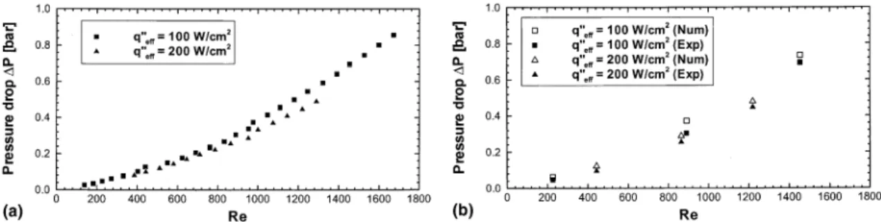
Fig. 4(a) shows the measured pressure drop in-creasing with inin-creasing Reynolds number. The largest
Fig. 4. (a) Variation of measured pressure drop with Reynolds number. (b) Comparison of measured and predicted values of pressure drop.
pressure drop of 0.86bar was measured at q00
eff¼
100 W=cm2 and Re¼1672. For the same Reynolds number, the pressure drop is lower for q00
eff¼200
W=cm2 because the higher water temperature at this condition decreases water viscosity.
A comparison between measured and predicted pressure drops for the two heat flux levels and different Reynolds numbers is shown in Fig. 4(b). The predicted pressure drop accounts for the pressure drop along the micro-channels, as well as the pressure losses associated with the abrupt contraction and expansion at the micro-channel inlet and outlet, respectively. A complete ex-pression for the total pressure drop is
DP¼DPc1þDPc2þDPchþDPe2þDPe1; ð18Þ
where the individual components are as follows.DPchis
the pressure drop across the micro-channels, which can be obtained from the numerical simulation. DPc1 and
DPc2 are the contraction pressure losses from the deep
plenum to the shallow plenum, and from the shallow plenum to the micro-channels, respectively. They are expressed as [23] DPc1¼ 1 2qf u 2 p2;in u2 p1;in þKc1 2 qfu 2 p2;in; ð19Þ and DPc2¼ 1 2qf u 2 in u2 p2;in þKc2 2 qfu 2 in; ð20Þ
where subscripts p1 and p2 denote the deep plenum and shallow plenum, respectively, and Kc1 and Kc2 are the
loss coefficients for the abrupt contractions. Similarly, DPe2andDPe2are the expansion pressure losses from the
micro-channels to the shallow plenum, and from the shallow plenum to the deep plenum, respectively, which are expressed as DPe2¼ 1 2qf u 2 p2;out u2 out þKe2 2 qfu 2 out; ð21Þ and DPe1¼ 1 2qf u 2 p1;out u2p2;out þKe1 2 qfu 2 p2;out; ð22Þ
where Ke1 and Ke2 are the loss coefficients associated
with the abrupt expansion. For the present heat sink test module geometry, the values ofKc1,Kc2,Ke1andKe2are
close to unity.
Fig. 4(b) shows good agreement between the mea-sured and predicted pressure drops. For a fluid with constant properties flowing through a rectangular channel, one would expect a linear relationship be-tween pressure drop and Reynolds number. There are several reasons for the slope change in the pressure drop characteristics in Figs. 4(a) and (b). First, for constant power input and water inlet temperature, the
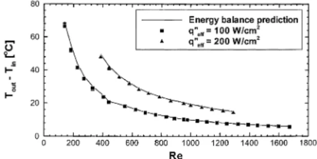
outlet water temperature should decrease with in-creasing Reynolds number as shown in Fig. 5. This in turn increases water viscosity, resulting in a larger pressure drop. Second, the inlet and outlet pressure losses are proportional to the square of velocity as indicated in Eqs. (19)–(22). Therefore, increasing Rey-nolds number produces a more pronounced increase in the inlet and outlet pressure losses. Another interesting observation from the experimental pressure drop re-sults is the absence of an early transition from laminar to turbulent flow within the Reynolds number range tested.
Fig. 5 compares the measured water temperature rise between the channel inlet and outlet, and theoretical values predicted from the simple energy balance qfVV c_ p;fðToutTinÞ ¼PW: ð23Þ
The excellent agreement between the two proves virtu-ally all the electrical power supplied by the cartridge heaters was removed by the water, and heat losses are indeed negligible.
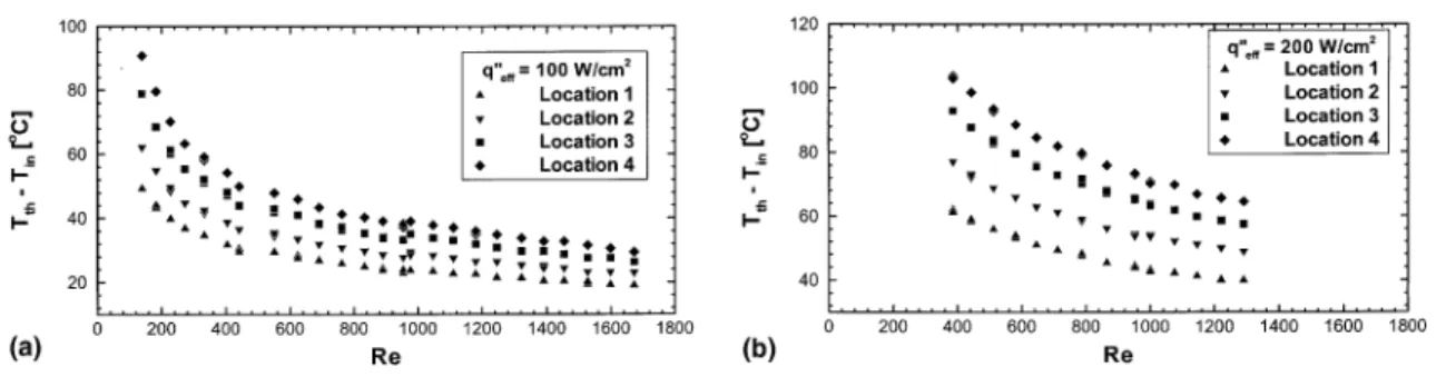
Figs. 6(a) and (b) show readings from the four ther-mocouples located inside the heat sink for q00
eff¼
100 W=cm2 and q00
eff¼200 W=cm 2
, respectively. The locations of the thermocouples are illustrated in Figs. 2(b) and 3. For each location, Figs. 6(a) and (b), show temperature decreases with increasing Reynolds num-ber, which is similar to the water temperature rise data in Fig. 5. For the same Reynolds number, the temper-ature increases along the flow direction. Also for the same Reynolds number, the temperature for a given location is higher forq00
eff¼200 W=cm 2
than for q00
eff¼
100 W=cm2.
Figs. 7(a) and (b) compare the temperatures mea-sured along the thermocouple line with numerical pre-dictions for the two heat fluxes and different Reynolds numbers. As expected, the heat sink temperature in-creases along the flow direction. The shallow dips in the predicted distributions correspond to locations of the deep slots where air is trapped. The good agreement between the measured and predicted temperatures Fig. 5. Comparison of experimental data and energy balance predictions for water temperature rise from heat sink inlet to outlet: (a)q00 eff¼100 W=cm 2 , (b)q00 eff¼200 W=cm 2 .
proves the conventional Navier–Stokes and energy equations can adequately predict the pressure drop and heat transfer characteristics of the micro-channel heat sink. Based on the present results as well as those re-ported in several recent studies (e.g., [17,19]), it is ex-pected that fluid flow and heat transfer within channels with characteristic dimensions greater than 100lm and Reynolds numbers below 1700 should follow the con-ventional Navier–Stokes equations.
Having validated the numerical method, a more de-tailed depiction of the heat transfer characteristics of the heat sinks is now discussed.
3.3. Local and average heat transfer characteristics
The temperature distributions at several key planes of the unit cell are illustrated in Figs. 8(a)–(e) for
q00
eff¼100 W=cm 2
andRe¼890. Note that the unit cell bottom wall (Wall A), channel bottom wall (Wall a), channel top wall (Wallc), and unit cell top wall (WallC) are allx–yplanes. Some interesting features are readily observed. The temperature increases along the longitu-dinalx-direction in all key planes except at the unit cell top wall (Wall C), where highest temperature is found about midway due to natural convection effects. In Fig. 8(a), the temperature distribution for the unit cell bot-tom wall (WallA) shows shallow dips at the locations of
the deep slots. These dips are virtually eliminated when moving to the channel bottom wall (Walla), Fig. 8(b), because of the excellent heat spread in the copper region between the two planes. There are very slight changes in the temperature gradient in the x-direction at the channel bottom wall (Walla), Fig. 8(b), and channel top wall (Wallc), Fig. 8(c). In fact, a linear temperature rise can be regarded as a good approximation for both planes. The temperature along the transversey-direction is virtually constant for all thex–yplanes just discussed. As expected, the temperature decreases from the unit cell bottom wall to the unit cell top wall.
Notice that the channel side wall (Wallb) is anx–z
plane. Fig. 8(e) shows higher temperatures for small z
values close to the channel bottom wall (Walla). Figs. 9(a)–(c) illustrate the heat flux distribution along the channel walls for q00
eff¼100 W=cm 2
and
Re¼890. The local heat flux,q00, is evaluated from
q00¼ ks oTs on C : ð24Þ
For all the channel walls, higher heat fluxes are en-countered near the channel inlet. This is attributed to the thin thermal boundary layer in the developing region. The heat fluxes vary around the channel periphery, ap-proaching zero in the corners where the flow is weak for Fig. 7. Comparison of experimental data and numerical predictions for temperature distribution along thermocouple line: (a)
q00 eff¼100 W=cm 2, (b) q00 eff¼200 W=cm 2.
Fig. 6. Thermocouple readings inside micro-channel heat sink versus Reynolds number for (a) q00
eff¼100 W=cm 2 and (b) q00 eff¼200 W=cm 2 .
a rectangular channel. The same conclusion concerning the vanishing heat flux in the corners is well documented in the heat transfer literature [24]. Fig. 9(b) shows heat transfer at the channel top wall (Wall c) is also very
weak. This is due to the very low thermal conductivity of the plastic cover plate (0.2 W/m°C) comparing with that of the copper block (401 W/m°C). Fig. 9(c) shows the heat flux along the channel side wall (Wallb) is higher Fig. 8. Numerical predictions of local temperature distribution forq00
eff¼100 W=cm 2
andRe¼890: (a) unit cell bottom wall (WallA), (b) channel bottom wall (Walla), (c) channel top wall (Wallc), (d) unit cell top wall (WallC), (e) channel side wall (Wallb).
than along the channel bottom wall (Walla) due to the short distance between the channel side walls and the large velocity gradient present.
The heat flux distribution can be better understood from the local Nusselt number distribution along the three channel walls, which is illustrated in Figs. 10(a)– (c). The local Nusselt number,Nu, is expressed as
Nu¼ q
00d
h
kfðTs;CTmÞ
; ð25Þ
whereTm is the fluid bulk temperature defined as
Tm¼ R AcuTdAc R AcudAc : ð26Þ
General features of the Nusselt number distribution are similar to those in the heat flux distribution, such as high value in the entrance region and low near the channel corners.
The fluid bulk temperature and average wall temper-atures at the unit cell bottom wall (Wall A), channel bottom wall (Walla), channel top wall (Wallc), unit cell top wall (WallC), and thermocouple plane are plotted in Fig. 11(a) with respect to longitudinal distance x for
q00
eff¼100 W=cm 2
andRe¼890. The fluid bulk temper-atureTmis given by Eq. (26), and the average wall
tem-peratures at the unit cell bottom wall (WallA), unit cell top wall (WallC), and thermocouple plane are defined as
TavðxÞ ¼ 1 W Z W 0 Ts;Cdy forz¼0; z¼H andz¼Hth: ð27Þ
The average wall temperatures at the channel bottom wall (Walla) and channel top wall (Wallc) are defined as
TavðxÞ ¼ 1 Wch Z WwþWch Ww Ts;Cdy forz¼Hw2andz¼Hw2þHch: ð28Þ Fig. 8. (continued).
As expected, Fig. 11(a) shows the average temperature decreases from the unit cell bottom wall (WallA) to the unit cell top wall (WallC). The liquid bulk temperature is lower than all five solid wall planes. Slope changes of the water bulk temperature and average temperatures at the channel bottom wall (Walla) and top wall (Wallc) are small, proving a linear temperature rise is a good approximation for these temperature distributions. The highest temperature point is located at the unit cell bottom wall (Wall A) immediately below the channel outlet.
Figs. 11(b) and (c) illustrate the average heat fluxq00
av
and average Nusselt number Nuav, respectively, at the
channel bottom wall (Walla), channel top wall (Wallc), and channel side wall (Wallb) forq00
eff¼100 W=cm 2
and
Re¼890. The definitions ofq00
avandNuavat the channel
top wall (Walla) and channel bottom wall (Wallc) are similar to that of the average wall temperature given in Eq. (28).q00
avandNuavat the channel side wall (Wallb)
are defined, respectively, as
q00 avðxÞ ¼ 1 Hch Z Hw2þHch Hw2 q00dz; ð29Þ NuavðxÞ ¼ 1 Hch Z Hw2þHch Hw2 Nudz ð30Þ
Fig. 9. Numerical predictions of local heat flux distribution forq00
eff¼100 W=cm 2
andRe¼890: (a) channel bottom wall (Walla), (b) channel top wall (Wallc), (c) channel side wall (Wallb).
fory¼Ww. Figs. 11(b) and (c) show the average heat
flux and average Nusselt number are very small at the channel top wall (Wallc) compared to those at the other two walls. In fact, it is safe to assume the channel top wall (Wallc) is adiabatic. For the channel bottom wall (Walla) and channel side wall (Wallb), the average heat flux and average Nusselt number are greatest near the channel inlet and decrease rapidly to nearly constant values. As indicated by Incropera and DeWitt [24], the hydrodynamic and thermal entry lengths of a circular tube may be estimated from
Lh¼0:05Re d; ð31Þ
Lth¼0:05Re Pr d; ð32Þ
respectively. For the rectangular channels of the present heat sink, the hydrodynamic and thermal entry lengths can be estimated by replacing the tube diameter d in Eqs. (31) and (32) with the hydraulic diameter,dh. For
the experimental conditions indicated in Fig. 11(c), the hydrodynamic and thermal entry lengths are 0.016m and 0.081 m, respectively, assuming Pr¼5:2. From Fig. 11(c), it can be seen that flow is fairly well devel-oped near channel exit, indicating Eq. (32) may not be accurate for rectangular channels. For most of the channel length, the average heat flux and average Fig. 10. Numerical predictions of local Nusselt number distribution forq00
eff¼100 W=cm 2
andRe¼890 : (a) channel bottom wall (Walla), (b) channel top wall (Wallc), (c) channel side wall (Wallb).
Nusselt number at the channel bottom wall (Walla) are smaller than the corresponding values at the channel side wall (Wallb).
The theoretical values of Nusselt number for rect-angular channels subjected to different thermal bound-ary conditions were summarized by Shah and London [25]. It would be ideal to compare the experimental re-sults with either those theoretical Nusselt numbers or the present numerical predictions. Unfortunately, the pre-sent experiments alone cannot provide sufficient infor-mation to fully characterize the local and average Nusselt number or heat flux. During the tests,
temper-atures were measured at six points, which include the channel inlet and outlet as well as four locations inside the heat sink. Due to the limited temperature data and the complex nature of the conjugate heat transfer problem, the local and average Nu and q00 cannot be determined without the numerical solution.
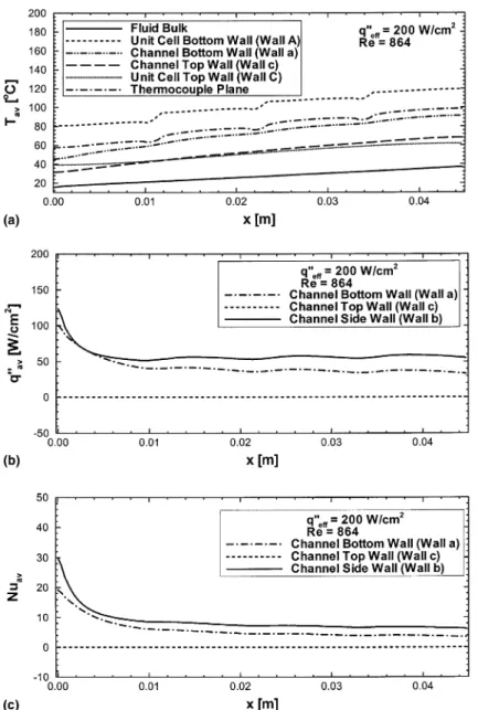
Figs. 12(a)–(c) show heat transfer characteristics for the conditions ofq00
eff¼200 W=cm 2
andRe¼864. The average temperatures and average heat fluxes in Figs. 12(a) and (b), respectively, have the same trends as those presented in Figs. 11(a) and (b), but higher values. The average Nusselt number in Fig. 12(c) is Fig. 11. Numerical predictions of average heat transfer characteristics forq00
eff¼100 W=cm 2
andRe¼890: (a) average temperature, (b) average heat flux, (c) average Nusselt number.
nearly identical to the one presented in Fig. 11(c). This is because the Nusselt number for laminar flow is de-termined solely by the channel geometry and the local flow conditions.
4. Conclusions
The fluid flow and heat transfer characteristics of a micro-channel heat sink were investigated both experi-mentally and numerically. Also presented and discussed was a detailed description of the local and average heat transfer characteristics of the heat sink, i.e. temperature,
heat flux, and Nusselt number. Key findings from the study are as follows:
1. The measured pressure drop is in good agreement with the predicted values. A gradual slope change in the pressure drop variation with Reynolds number is attributed to the temperature dependence of water viscosity, and the increasing contraction and expan-sion pressure losses at the channel inlet and outlet, re-spectively, with increasing Reynolds number. 2. The early transition from laminar to turbulent flow
cited in previous micro-channel studies was never ob-served in the present study within the tested Reynolds number range 139–1672.
Fig. 12. Numerical predictions of average heat transfer characteristics forq00
eff¼200 W=cm 2
andRe¼864: (a) average temperature, (b) average heat flux, (c) average Nusselt number.
3. Higher Reynolds numbers are beneficial at reducing both the water outlet temperature and the tempera-tures within the heat sink, alas at the expense of greater pressure drop.
4. Very good agreement was achieved between the ex-perimental data and numerical predictions for the temperature distribution within the heat sink. 5. At any longitudinal distancexalong the
micro-chan-nel, the bulk liquid constitutes the region of lowest temperature in the unit cell, while the highest temper-ature is encountered in the bottom wall (WallA) im-mediately below the channel outlet. The water bulk temperature and average temperatures at the channel bottom wall (Walla) and top wall (Wall c) increase fairly linearly along the longitudinal direction. 6. The channel top wall (Wallc) can be assumed
adia-batic due to the small thermal conductivity of the plastic cover plate. For the channel bottom wall (Walla) and side wall (Wallb), much higher heat flux and Nusselt number values are encountered near the channel inlet. The heat flux and Nusselt number also vary around the channel periphery, approaching zero near the corners.
7. Excellent agreement between both the pressure drop and heat sink temperature data and corresponding numerical predictions proves the conventional Na-vier–Stokes and energy equations can accurately pre-dict the heat transfer characteristics of micro-channel heat sinks for the channel size employed in the pre-sent study and recommended for practical cooling ap-plications.
Acknowledgements
The authors are grateful for the support of the Office of Basic Energy Sciences of the US Department of En-ergy (Award No. DE-FG02-93ER14394 A7).
References
[1] D.B. Tuckerman, R.F.W. Pease, High-performance heat sinking for VLSI, IEEE Electron. Dev. Lett. EDL-2 (1981) 126–129.
[2] R.W. Keyes, Heat transfer in forced convection through fins, IEEE Trans. Electron Dev. ED-31 (1984) 1218–1221. [3] V.K. Samalam, Convective heat transfer in microchannels,
J. Electron. Mater. 18 (1989) 611–617.
[4] R.J. Phillips, Micro-channel heat sinks, in: A. Bar-Cohen, A.D. Kraus (Eds.), Advances in Thermal Modeling of Electronic Components, vol. 2, ASME Press, New York, 1990, pp. 109–184.
[5] R.W. Knight, J.S. Goodling, D.J. Hall, Optimal thermal design of forced convection heat sinks – analytical, ASME J. Electron. Packaging 113 (1991) 313–321.
[6] R.W. Knight, D.J. Hall, J.S. Goodling, R.C. Jaeger, Heat sink optimization with application to microchannels, IEEE Trans. Components, Hybrids, Manufac. Technol. 15 (1992) 832–842.
[7] A. Bejan, A.M. Morega, Optimal arrays of pin fins and plate fins in laminar forced convection, ASME J. Heat Transfer 115 (1993) 75–81.
[8] D.Y. Lee, K. Vafai, Comparative analysis of jet impinge-ment and microchannel cooling for high heat flux appli-cations, Int. J. Heat Mass Transfer 42 (1999) 1555–1568. [9] A. Weisberg, H.H. Bau, J.N. Zemel, Analysis of
micro-channels for integrated cooling, Int. J. Heat Mass Transfer 35 (1992) 2465–2474.
[10] A.G. Fedorov, R. Viskanta, Three-dimensional conjugate heat transfer in the microchannel heat sink for electronic packaging, Int. J. Heat Mass Transfer 43 (2000) 399–415. [11] T. Kishimito, T. Ohsaki, VLSI packaging technique using liquid-cooled channels, IEEE Trans. Components, Hy-brids, Manufac. Technol. CHMT-9 (1986) 328–335. [12] S. Sasaki, T. Kishimito, Optimal structure for
microgro-oved cooling fin for high-power LSI devices, Electron. Lett. 22 (1986) 1332–1334.
[13] D. Nayak, L.T. Hwang, I. Turlik, A. Reisman, A high performance thermal module for computer packaging, J. Electron. Mater. 16(1987) 357–364.
[14] M.M. Rahman, F. Gui, Experimental measurements of fluid flow and heat transfer in microchannel cooling passages in a chip substrate, Adv. Electron. Packaging ASME EEP-4 (1993) 495–506.
[15] M.M. Rahman, F. Gui, Design, fabrication, and testing of microchannel heat sinks for aircraft avionics cooling, in: Proceedings of the 28th Intersociety Energy Conversion Engineering Conference, vol. 1, 1993, pp. 1–6.
[16] T.S. Ravigururajan, J. Cuta, C.E. McDonald, M.K. Drost, Single-phase flow thermal performance characteristics of a parallel micro-channel heat exchanger, in: National Heat Transfer Conference, vol. 7, ASME HTD-329, 1996, pp. 157–166.
[17] T.M. Harms, M.J. Kazmierczak, F.M. Cerner, A. Holke, H.T. Henderson, J. Pilchowski, K. Baker, Experimental investigation of heat transfer and pressure drop through deep microchannels in a (1 0 0) silicon substarte, in: Proceedings of the ASME Heat Transfer Division, HTD-351, 1997, pp. 347–357.
[18] K. Kawano, K. Minakami, H. Iwasaki, M. Ishizuka, Micro channel heat exchanger for cooling electrical equip-ment, Appl. Heat Transfer Equip., Syst. Educ. ASME HTD-361-3/PID-3 (1998) 173–180.
[19] T.M. Harms, M.J. Kazmierczak, F.M. Cerner, Developing convective heat transfer in deep rectangular microchannels, Int. J. Heat Fluid Flow 20 (1999) 149–157.
[20] M.M. Rahman, Measurements of heat transfer in micro-channel heat sinks, Int. Commun. Heat Mass Transfer 27 (2000) 495–506.
[21] S.V. Patankar, Numerical Heat Transfer and Fluid Flow, Hemisphere, Washington, DC, 1980.
[22] S.V. Patankar, A numerical method for conduction in composite materials, flow in irregular geometries and conjugate heat transfer, in: Proceedings of 6th Inter-national Heat Transfer Conference, vol. 3, 1978, pp. 297– 302.
[23] N.E. Todreas, M.S. Kazimi, Nuclear Systems I, Hemi-sphere, New York, 1990.
[24] F.P. Incropera, D.P. DeWitt, Fundamentals of Heat and Mass Transfer, fourth ed., Wiley, New York, 1996.
[25] R.K. Shah, A.L. London, Laminar Flow Forced Convec-tion in Ducts: A Source Book for Compact Heat Ex-changer Analytical Data, Suppl. 1, Academic press, New York, 1978.