Chapter 1
1.
Introductory Overview
The main goal of this chapter is to review fundamental aspects of analogue and digital signals and systems, digital codes, the binary, decimal and hexadecimal numbering systems. First, it briefly describes the differences between floating-point and fixed–point processor cores, and looks at the effect on performing mathematical operations and clock cycles used.
It also contains the C Programming Language operators used by the MSP430 to perform logical and mathematical operations.
Good software practices are presented at the end of the chapter to take advantage of the low power capabilities of the MSP430.
Topic Page 1.1 Analogue and digital signals ... 1-3
1.2 Mathematical notations ... 1-4 1.2.1 The Binary Number Base System... 1-5 1.2.2 The Hexadecimal Number Base System... 1-5 1.2.3 Decimal to Binary Conversion... 1-7 1.2.4 Binary to Decimal Conversion... 1-8 1.2.5 Binary to Hexadecimal Conversion ... 1-9 1.2.6 Hexadecimal to Binary Conversion ... 1-9 1.2.7 Hexadecimal to Decimal Conversion... 1-10 1.2.8 Decimal to Hexadecimal Conversion... 1-10 1.2.9 Mathematical operations ... 1-11 1.3 Floating-point and fixed-point arithmetic ... 1-13 1.4 How to read technical specifications in MSP430 datasheets ... 1-19 1.5 Programming issues ... 1-22 1.5.1 Introduction ... 1-22
1.5.2 Programming styles ...1-23 1.5.3 Data declaration...1-25 1.5.4 Operators and expressions ...1-27 1.5.5 Masks...1-30 1.5.6 Bit testing ...1-30 1.5.7 Bit shifts ...1-30 1.6 Good software practices for low power consumption ....1-32
1.6.1 C coding tips ...1-32 1.6.2 Principles for low power applications...1-32 1.7 Quiz ...1-33 1.8 FAQs ...1-35
Analogue and digital signals
1.1
Analogue and digital signals
In nature, any measurable quantity in time or in space can be considered a signal. The velocity of a body, as function of time or as function of position, can be represented by a signal. The signal is designed by analogue or continuum in time if the quantity is known at any time instant. If the signal is only known for discrete time instants, is designed as discrete time signal. An example of an analogue signal is shown in Figure 1-1.
Figure 1-1. Analogue signal example.
0 0.1 0.2 0.3 0.4 0.5 0.6 0.7 0.8 0 0.2 0.4 0.6 0.8 1 1.2 1.4 1.6 1.8 2 t x( t)
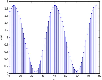
This signal can be discretized in time, using a sampling period, T, as shown in Figure 1-2.
Figure 1-2. Discrete analogue signal.
0 10 20 30 40 50 60 70 80 0 0.2 0.4 0.6 0.8 1 1.2 1.4 1.6 1.8 2 n x( n )
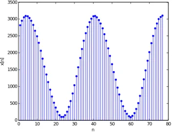
The information contained in the signal only can be used by a computer if an amplitude conversion from the analogue domain to the digital domain is performed. The result of the analogue signal conversion, performed by a 12-bit Analogue-to-Digital Converter (ADC) with 2.5 V full-scale, is shown in Figure 1-3.
Figure 1-3. Quantized digital signal.
0 10 20 30 40 50 60 70 80 0 500 1000 1500 2000 2500 3000 3500 n x[n ]
1.2
Mathematical notations
A base number is a notation that through symbols represents a consistent numerical value. So, depending on the numerical basis the numerical representation 11 may correspond to: eleven for base
decimal (or radix decimal), three for the binary base, or other numbers if other bases are used.
Before looking at the numerical representation used by computers, let us review the decimal numerical base representation. The representation 123410 can be written as follows using a positional representation.
1x10³ + 2x10² + 3x101 + 4x100
Each of the symbols is multiplied by a weight of base 10, which gives the representation called base 10 (radix 10). As it moves from right to left, the weight is increased. While the least significant digit to the right of the representation is 4, the most significant digit to the right of representation is 1. Each of them is multiplied by a value of base 10, depending of the position it assumes in the representation. The set of symbols available belongs to {0, 1, 2, 3, 4, 5, 6, 7, 8, 9}. In general, if b is the base, a numerical value that is represented by that numerical base is given by:
Mathematical notations
Where n is the length of the numerical representation and {an-1, an-2, …, a0} is the numerical representation ordered increasingly. These digits are natural numbers in the set {0, …, b}.
1.2.1
The Binary Number Base SystemComputers can only take two states, so they use the binary base (base 2). The states allowed are “open” or “closed”, “high” or “low”, “1” or “0”. The last two symbols are used in the binary numerical representation.
A binary number can be expressed as:
0101002
Each binary digit (bit) is used to represent a portion of the value. As it is a positional representation, it can be expressed by the following alternative representation shown in Table 1-1.
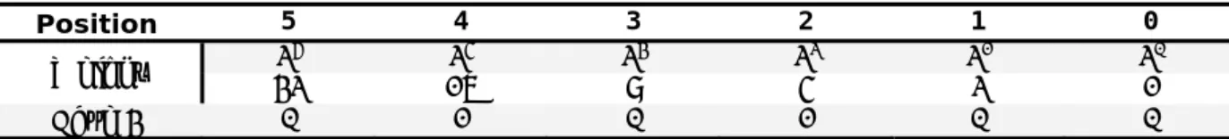
Table 1-1. Binary number representation.
Position 5 4 3 2 1 0 25 24 23 22 21 20 Weight 32 16 8 4 2 1 Base 2 0 1 0 1 0 0 0x25 + 1x24 + 0x23 + 1x22 + 0x21 + 0x20 That is, the number corresponds to 2010 in the decimal base.
1.2.2
The Hexadecimal Number Base SystemA difficulty that arises from the binary system is its verbosity. To represent the value 20210 requires eight binary digits. The decimal version requires only three decimal digits, and thus, represents numbers much more compactly than does the binary numbering system. This fact is particularly problematic for the design of binary computer systems. When dealing with large values, binary numbers quickly become too unwieldy. The hexadecimal (base 16) numbering system solves these problems. Hexadecimal numbers offer two features:
Hexadecimal numbers are very compact;
It is easy to convert from hexadecimal to binary and from binary to hexadecimal.
Since we will often need to enter hexadecimal numbers into the computer system, we will need a different mechanism for representing hexadecimal numbers, because you cannot enter a subscript to denote the radix of the associated value.
The set of symbols used are those in the series {0, 1, 2, 3, 4, 5, 6, 7, 8, 9, A, B, C, D, E, F}. This representation comes directly from the binary representation. Combining the value 0101002 in groups of four bits (four bits = 1 nibble), starting from the right side, the following representation is obtained:
0001 01002
It should be noted that two zeros have been introduced in the second group to complete it, without introducing any change in the represented value. This representation can be converted directly into the hexadecimal numerical base as been 1416. (0x14). Making use of conversion table (Table 1-2):
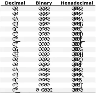
Table 1-2. Conversion bases.
Decimal Binary Hexadecimal
00 0000 0x00 01 0001 0x01 02 0010 0x02 03 0011 0x03 04 0100 0x04 05 0101 0x05 06 0110 0x06 07 0111 0x07 08 1000 0x08 09 1001 0x09 10 1010 0x0A 11 1011 0x0B 12 1100 0x0C 13 1101 0x0D 14 1110 0x0E 15 1111 0x0F 16 1 0000 0x10
This table provides all the information needed to convert from one number base into any other number base for the decimal values from 0 to 16.
To convert a hexadecimal number into a binary number, simply break the binary number into 4-bit groups beginning with the least significant bit (LSB) and substitute the corresponding four bits in binary for each hexadecimal digit in the number.
For example, to convert the hexadecimal value 0x0ABCD (0ABCD16) into a binary value, simply convert each hexadecimal digit according to the table above. The binary equivalent is:
Mathematical notations
To convert a binary number into hexadecimal format is almost as easy. The first step is to pad the binary number with leading zeros, to make sure that the binary number contains multiples of four bits. For example, given the binary number 10 1100 10102, the first step would be to add two bits in the MSB position so that it contains 12 bits. The revised binary value is 0010 1100 10102.
The next step is to separate the binary value into groups of four bits, e.g., 0010 1100 10102. Finally, look up these binary values in the table above and substitute the appropriate hexadecimal digits, e.g., 0x2CA.
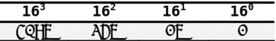
The weighted values for each position are as follows:
Table 1-3. Weighted values for each position of 0x2CA.
163 162 161 160
4096 256 16 1
1.2.3
Decimal to Binary ConversionExample 1: Decimal number, 72110, to binary conversion.
72110 = 700 + 20 + 1 = 7x10² + 2x101 + 1x100
This conversion consists of continuously subtracting the highest power of 2 not higher than the remainder - if you can subtract, mark the corresponding position with '1', else with '0'".
For this example, local in base 2, which is the power below the highest part in base 10.
210 = 1024 Higher than the third power decimal part value
used, 103;
29 = 512 Most Significant Bit – MSB: 1x29;
721 - 512 = 209
28 = 256 Higher than 209, the second bit: 0x28;
27 = 128 Third bit is: 1x27;
209 - 128 = 81
26 = 64 Fourth bit is: 1x26;
81 - 64 = 17
25 = 32 Higher than 17, the fifth bit is: 0x25;
24 = 16 Sixth bit is: 1x24;
23 = 8 Higher than 1, the seventh bit: 0x23;
22 = 4 Higher than 1, the eighth bit: 0x22;
21 = 2 Higher than 1, the ninth bit: 0x21;
20 = 1 Tenth bit (LSB - Least Significant Bit): 1x20; Result: 72110 = 10110100012
Another way to convert from decimal to binary base is to evaluate the remainder of a division:
Example 2: Convert the decimal number, 10310, to binary notation.
This method consists of continuously dividing by 2. The division remainder value is the corresponding position binary digit. 10310 = 100 + 3 = 1x10² + 0x101 + 3x100 10310/2 = 51 Remainder: 1 (LSB) 51/2 = 25 Remainder: 1 25/2 = 12 Remainder: 1 12/2 = 6 Remainder: 0 6/2 = 3 Remainder: 0 3/2 = 1 Remainder: 1 1/2 = 0 Remainder: 1 (MSB) Result: 10310 = 11001112
1.2.4
Binary to Decimal ConversionExample 3: Convert to decimal notation the binary number
10101112.
This method is the inverse of the method presented in Example 1.
The binary number was 7 bits:
MSB: 1 = 1 x 26 = 64
Mathematical notations 5th bit: 1 = 1 x 24 = 16 4th bit: 0 = 0 x 23 = 0 3rd bit: 1 = 1 x 22 = 4 2nd bit: 1 = 1 x 21 = 2 LSB: 1 = 1 x 20 = + 1 Result: 10101112 = 8710
1.2.5
Binary to Hexadecimal ConversionThe conversion from an integer binary number to hexadecimal is accomplished by:
1. Breaking the binary number into 4-bit sections from the LSB to the most significant bit (MSB).
2. Converting the 4-bit binary number to its hexadecimal equivalent.
Example 4: Convert the binary value 10101111101100102 to hexadecimal notation.
1010 1111 1011 0010 A F B 2
Result: 0xAFB2 = 10101111101100102
1.2.6
Hexadecimal to Binary ConversionThe conversion from an integer hexadecimal number to binary is accomplished by:
1. Converting the hexadecimal number to its 4-bit binary equivalent. 2. Combining the 4-bit sections by removing the spaces.
Example 5: Convert the hexadecimal value 0x0AFB2 to binary
notation.
A F B 2 1010 1111 1011 0010
This yields the binary number 10101111101100102 or
1.2.7
Hexadecimal to Decimal ConversionTo convert from hexadecimal to decimal, multiply the value in each position by its hexadecimal weight and add each value.
Example 6: Convert the hexadecimal number 0x0AFB2 to decimal
notation.
A*163F*162 B*161 2*160
10*4096 15*256 11*16 2*1
40960 + 3840 + 176 + 2 = 4497810
1.2.8
Decimal to Hexadecimal ConversionTo convert decimal to hexadecimal is slightly more difficult. The typical method to convert from decimal to hexadecimal is repeated division by 16. While we may also use repeated subtraction by the weighted position value, it is more difficult for large decimal numbers.
Repeated Division by 16
For this method, divide the decimal number by 16, and write the remainder to the side as the least significant digit. This process is continued by dividing the quotient by 16 and writing the remainder until the quotient is 0. When performing the division, the remainders, which will represent the hexadecimal equivalent of the decimal number, are written beginning with the least significant digit (right). Each new digit is then written to the next most significant digit (left) of the previous digit.
Example 7: Convert the decimal number 4497810 to hexadecimal notation.
Division Quotient Remainder Hexadecimal number 44978 / 16 2811 2 2
2811 / 16 175 11 B2
175 / 16 10 15 FB2
Mathematical notations
1.2.9
Mathematical operationsAs an alternative to the use of base representation in subscript form, it is more common to use letters d for decimal, h for hexadecimal, and b for binary, while the decimal representation is used without any suffix letter. It is also a common practice represent a hexadecimal number with the suffix 0x.
Mathematical operations can be performed using any one of these bases. In binary, the sum operation also uses the carry concept:
0 + 0 = 0 without carry 0 + 1 = 1 without carry 1 + 1 = 0 with carry equal 1
An example of the sum of two binary numbers:
010111012
+ 000101102
011100112
Sometimes the microprocessor does not have dedicated hardware to carry out more complex mathematical operations such as multiplication or the square root of a number. In such cases, it is necessary to emulate these mathematical operations in software. Another operation to carry out is multiplication.
010111012 01102 00000000 01011101 01011101 + 00000000 010001011102
Other operations are possible, but the algorithms are more complicated.
So far, only the representation of positive numbers has been introduced. However there is also the need to use negative numbers. This representation can be achieved using the one’s complement or two’s complement methods.
The one’s complement is achieved by complementing the number representation bit-by-bit. Here complement means transform 0 -> 1 and transform 1 -> 0.
000101002 One’s complement 111010112
Because the most significant bit to the left is high (1), the representation corresponds to a negative number. However, this representation cannot be used directly to carry out mathematical operations. In this case, the two’s complement presentation should be used. To generate a two’s complement number, take the one’s complement and add 1 to it. In this representation, the task "subtract two numbers" has been transformed to "add the two’ complement" - so a totally different operation 'ADD' instead of 'SUB' is used.
Example 8: Perform the subtraction operation between 010111012 and 000101002.
0001 01002 One’s complement + 1 = 1110 11002
It is now possible to correctly carry out the subtraction operation:
0101 11012 - 0001 01002
It is equal to: 0101 11012
+ 1110 11002 <- Two’s complement representation
0100 10012
The result is positive because the most significant bit is zero.
Example 9: Perform the subtraction operation between 101000112 and 000101102.
0001 01102 One’s complement + 1 = 1110 10102
1010 00112 - 0001 01102
It is equal to: 1010 00112
+ 1110 10102 <- Two’s complement representation
1000 11012
Floating-point and fixed-point arithmetic
1.3
Floating-point and fixed-point arithmetic
One aspect of numberings systems not mentioned so far is the representation of fractional numbers. There are two different ways to represent fractional numbers: the first uses a fixed point, while the second uses a floating point.
Positional representation and numerical base of a number
In positional representation, introduced by the Babylonians, the symbols are arranged in sequence and become more significant as they progress to the left, the weight being influenced by the position occupied in the number. A compact representation, using a limited set of symbols, is thus achieved.
If b is the numerical base used and ai is a digit in that base, then any positive integer A, constituted by n digits, can be represented by
Equation 1.1: 0 0 1 n 1 n 1 n i 0 i i i i
b
a
b
...
a
b
a
A
Eq. 1.1Table 1-4 details the numerical bases and their digits, most used in numerical representation in microprocessor systems.
Table 1-4. Numerical representations in microprocessor systems.
Bases Digits
Binary 0, 1
Octal 0, 1, 2, 3, 4, 5, 6, 7
Decimal 0, 1, 2, 3, 4, 5, 6, 7, 8, 9
Hexadecimal 0, 1, 2, 3, 4, 5, 6, 7, 8, 9, A, B, C, D, E, F
Binary base signed numbers representation
For any of the representations in Table 1-4, there is the need to represent both positive and negative numbers. Typically, the most significant bit (MSB) value 0 is used to represent positive signs and the MSB value 1 is to represent negative signs. The remaining bits represent the magnitude of the number. Three different notations are used for the fixed-point representation of signed numbers (Table 1-5).
In the sign and absolute value notation, the MSB is reserved to indicate the sign, and the other bits represent the magnitude of the value. This notation has some disadvantages, namely, the value of zero has two representations, and before making any operation it is necessary to determine the sign of operands involved.
In one’s complement notation, as in the previous notation, the MSB is reserved for the sign of the number and magnitude of negative
values is complemented bit by bit, with the same disadvantages as the previous notation.
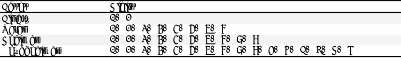
Table 1-5. Notations for the fixed-point representation of signed numbers.
Binary value 000 001 010 011 100 101 110 111
Sign and absolute value +0 +1 +2 +3 -0 -1 -2 -3
One’s complement +0 +1 +2 +3 -3 -2 -1 -0
Two’s complement +0 +1 +2 +3 -4 -3 -2 -1
In the two’s complement representation, the MSB is reserved, as in the previous notation, to indicate the sign of the number. The remaining bits use the magnitude of negative values complemented bit by bit and incremented. This method eliminates the double representation of the zero value and it makes the range of positive values below the range of negative values. The main advantage of this notation is the ability to perform subtraction operations, without needing to take the sign of the operands into consideration.
Fixed point numerical representation
Fixed-point arithmetic, compared with floating-point arithmetic, is easily implemented in a small memory space and it is fast to execute. For these reasons, it is well-suited to real-time applications on processors that do not have a floating point coprocessor. Internally, the arithmetic processing unit takes the value as integer, but the programmer separates the fractional component of the number from the integer component by an imaginary point. This is the basic principle of any real time implementation dealing with magnitudes that are not integer values.
A fixed point integer value, A, with n bit, is given by the notation
(UQp.q), where U represents the unsigned (no sign bit) notation,
p + q = n identifies an unsigned number au, p bits represent the integer component and q bits represent the fractional component.
The relationship between these three quantities is given in Equation 1.2. The maximum and minimum limits of the representation are defined by Equation 1.3, and the resolution r is defined by Equation 1.4. q u 2 A a Eq. 1.2 q q p u 2 1 2 a 0 Eq. 1.3 q 2 r Eq. 1.4
The notation normally used for the fixed-point representation of a two’s complement number is:
Floating-point and fixed-point arithmetic
Where m represents the number of bits of the integer component
and n represents the number of bits of the fractional component. The sum m + n + 1 is equal to the total number of bits available to
represent the numerical value (word length). The extra bit is required to store the value of the sign of the number.
The maximum and minimum limits are defined by Equation 1.5.
q q p s q q p 2 1 2 a 2 2 Eq. 1.5
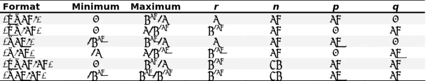
Some of the fixed point formats are shown in Table 1-6. For simplification, when p and q are null, the formats are ignored.
Table 1-6. Fixed point formats.
Format Minimum Maximum r n p q
(UQ16.) 0 216-1 1 16 16 0 (UQ.16) 0 1-2-16 2-16 16 0 16 (Q15.) -215 215-1 1 16 15 0 (Q.15) -1 1-2-15 2-15 16 0 15 (UQ16.16) 0 216-1 2-16 32 16 16 (Q15.16) -215 215-2-16 2-16 32 15 16
If the fractional component of the number is not fully represented by the q bits reserved for that purpose, the representation will not be
exact, with a representation error less than the value of the LSB (Last Significant Bit).
The Q3.12 format places the sign bit after the fourth binary digit from the right, and the next 12 bits contain the two’s complement fractional component. The approximate permitted range of numbers in Q3.12 representation is {-8, 8} and the smallest fractional resolution is 2-12 2.441x10⁻⁴.
Table 1-7. Q3.12 format.
Bit 15 14 13 12 11 10 9 … 0
Value S I3 I2 I1 Q11 Q10 Q9 … Q0
If you consider a microcontroller that only performs mathematical operations with 8 bits, it is necessary to develop a set of mathematical routines to perform operations with higher numerical data values. One way is to use 4 bytes, resulting in a total of 32 bits
to store the representation of the numerical value. These 32 bits are used as follows:
20 bits: Integer component representation;
12 bits: Fractional component representation.
The integer component can represent a maximum value of 220 = 1048576. With respect to the fractional component, the minimum value that can be represented by 12 bits is 2-12, allowing a precision to the third decimal value without error.
In the following figure, this arrangement of 4 bytes is shown and the binary point position.
**** **** **** **** Byte 3 Byte 2 Byte 1 Byte 0
In addition, the representation can be in Q.15 format. This format places the sign bit at the leftmost binary digit, and the next 15 leftmost bits contain the two’s complement fractional component. The approximate permitted range of numbers in Q.15 representation is {-1, 1} and the finest fractional resolution is 2-15 3.05x10⁻⁵.
Table 1-8. Q.15 format.
Bit 15 14 13 12 11 10 9 … 0
Value S Q14 Q13 Q12 Q11 Q10 Q9 … Q0
Example 1: Convert the decimal number 123.04510 into its hexadecimal representation:
Decimal representation: 123.04510
Integer component: 12310 = 7B16
Fractional component: 0.04510 = 0.0B816
The representation conversion gives: 123.04510 = 7B.0B816
Example 2: Convert the decimal number 8751.13510 into a hexadecimal representation:
Integer component: 875110 = 222F16
Fractional component: 0.13510 = 0.22816
Floating-point and fixed-point arithmetic
An alternative way to represent a number consists of using a floating-point representation.
In floating-point number representation, the radix point position can float relatively to the significant digits of the number. This detail allows the support of a much wider range of values when compared with the fixed point number representation. Before the 1985 IEEE 754 standard, the floating-point representation of numerical values was made through different formats and word widths. Nowadays, the IEEE 754 standard is accepted almost by all kind of computers. From the set of formats supported, the most widely used are the single-precision (32-bit) and double-precision (64-bit). Moreover, the standard also establishes others kinds of formats: "quad" binary and decimal point (128-bit); and double decimal floating-point (64-bit). Less used are the extended precision (80-bit) and half-precision (16-bit) formats. The last one appears in the IEEE 754r proposed revision. Standard current version is IEEE 754-2008, which was published in August 2008.
In the data structure of floating-point numbers, the most significant bit is the sign bit (S), followed by the exponent that is biased. The mantissa without the most significant bit is stored after the exponent in the fraction field. The next figure illustrates the data structure.
Figure 1-4. Floating-point data structure.
The exponent is biased by the (2e − 1) − 1, where e is the exponent number of bits. This solution was adopted because exponents must be signed, and the two's complement representation will require extra computational work if it was used.
The values of the biased exponent and mantissa determine the data meaning:
The number is said to be normalized (most significant bit of the mantissa is 1), if exponent ranges between 0 and 2e− 1;
The number is said to be de-normalized (most significant bit of the mantissa is 0), if the exponent is 0 and fraction is not 0. Most important de-normalized numbers: +0.0: 0x0000; -0.0: 0x8000;
The number is ±0 (depending on the sign bit), if exponent is 0 and fraction is 0;
The number is ±infinity (depending on the sign bit), if exponent = 2e− 1 and fraction is 0;
The number being represented is not a number (NaN), if exponent = 2e− 1 and fraction is not 0.
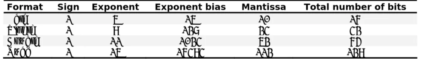
The IEEE 754 binary formats have the following organization:
Table 1-9. IEEE 754 binary formats.
Format Sign Exponent Exponent bias Mantissa Total number of bits
Half 1 5 15 10 16
Single 1 8 127 23 32
Double 1 11 1023 52 64
Quad 1 15 16383 112 128
A number X has the value: X = (1)S 2exponentexponentbias mantissa.
Lets see how to code a floating-point number.
Example 3: Consider the decimal number 14.23510.
The number integer part can be converted to the binary value 11102, while the fractional number part is converted to the binary value
0.001111000010100011112. The number can be represented in the binary base as:
1110.001111000010100011112
The number normalization requires that radix is moved to the left:
1.110001111000010100011112 23
We can now code the floating-point representation in the single format (32-bit) as:
Sign (1-bit): 0 (the number is positive);
Exponent (8-bit): 127 + 3 = 130 = 10000010;
Fraction (23-bit): 11000111100001010001111 (fractional part of the mantissa).
Finally, the floating-point code.
Table 1-10. Example 3 - Floating-point code.
Sign Exponent Fraction
0 10000010 11000111100001010001111
How to read technical specifications in MSP430 datasheets
1.4
How to read technical specifications in MSP430 datasheets
The manufacturers of electronic devices provide datasheets containing the specifications detailing the characteristics of the part/device. In order to implement a printed circuit board to accommodate a particular device, it is necessary to know the electrical characteristics of the device and the pin-out functions, without detailing the internal operation (example Figure 1-4).
In addition to the datasheets, more complex devices are provided with documents that aid the development of applications, such as: application notes, user guides, design guides, package drawings, etc. These documents are as necessary as datasheets, and can usually be found on the manufacturer’s web site. Typically, this is the best place to obtain the necessary information, because the documents are updated frequently and when a bug or an error in the documents are found, errata are posted with the latest information. Normally, the datasheets include information regarding the part number of the device or device series and their number variant. The electrical characteristics contain the maximum and minimum voltages, permitted current drain for a particular chip, as well as the pin-out of the device. Also included are the power source schematics and which external components are supported. The datasheets also specify the clock frequencies and the electrical characteristics of each pin.
Also provided may be the noise tolerance or the noise created by the components of the device, as well as the capacitance, inductance and resistance of the inputs and outputs.
Usually, the datasheets contain the physical tolerances of the devices. Just as the operating characteristics indicate the conditions for proper operation, the tolerances indicate the maximum and minimum conditions that the component can withstand, without sustaining permanent damage.
One thing to bear in mind when looking at a MSP430 device datasheet, is that the device has a great number of peripherals, each terminal usually has more than one function. Each datasheet has a table with the description of individual terminal function. Some of the terminals have specific functions, for example power supply and externals crystals, but most terminals could be used for more that one function. Figure 1-5 shows an example of the various terminal functions in an MSP430F44x device. Pin number 2 shares P6.3 with A3, which means that this pin can be used as the digital Input/Output Port 6 bit 3 or the 3rd analogue input. Additional details are provided in the following chapters.
Figure 1-5. MSP430F44x terminals.
It is important to state that the signals that appear at the input/output terminals can be replaced by putting software written in C or assembly language inside the microcontroller. This may be obvious for users that are used to working with microcontrollers and FPGAs, but for some beginners that are used to working with analogue electronics, TTL or other passive circuits and now starting to work with these devices, it is not so clear. Microcontrollers and FPGAs do not work without internal software, also known as firmware.
By putting ones and zeros in some memory position inside the microcontroller, the way it works is changed. So, the software influences hardware.
The configuration and name of each input/output pin to the chip is fundamental to understanding the operation when mounted on a printed circuit. Most peripherals of the microcontroller are first presented in the User’s Guide as a Block Diagram (example Figure 1-5). This diagram shows how the peripheral is influenced by the bits defined in the registers.
How to read technical specifications in MSP430 datasheets
Figure 1-6. Example of the MSP430F44x clock module block diagram.
Let us look at the following detail and analyse what it means:
This is a multiplexed block that has four inputs and one output. The input that is redirected to the output is selected using the SELMx bits. If the SELMx bits are 00, the first input is routed to the multiplexer output line, if SELMx bits are 01, the second input is routed to the multiplexer output line, and so on.
SELMx is a mnemonic, meaning a way to introduce numbers in the registers without knowing their value, but using an easy way to remember them. In this case, SELMx (Select Multiplexer) has two bits, so the code should use SELM0 and SELM1, with SELM0 the less significant bit.
Now it is understood how the peripheral works, the next step is to find the associated register(s) needed to be configured in order to provide the desired operation. In all TI User’s Guides, this information is at the end of the chapter for a particular peripheral. Continuing the last example, SELMx appears in the FLL_CTL1 register. It looks like:
FLL_CTL1, FLL+ control register 1
7 6 5 4 3 2 1 0
- SMCLKOFF XT2OFF SELMx SELS FLL_DIVx
Bit Description
6 SMCLKOFF Disable the submain clock signal (SMCLK):
SMCLKOFF = 0 SMCLK active
SMCLKOFF = 1 SMCLK inactive
5 XT2OFF Disable the second crystal oscillator (XT2):
XT2OFF = 0 XT2 active XT2OFF = 1 XT2 inactive 4-3 SELMx Select the master clock (MCLK) source:
SELM1 SELM0 = 0 0 DCO SELM1 SELM0 = 0 1 DCO SELM1 SELM0 = 1 0 XT2 SELM1 SELM0 = 1 1 LFXT1 2 SELS Select the submain clock (SMCLK) source:
SELS = 0 DCO
SELS = 1 XT2
1-0 FLL_DIVx Select the auxiliary clock (ACLK) signal divider: FLL_DIV_0 = 0 0 Divider factor: /1 FLL_DIV_1 = 0 1 Divider factor: /2 FLL_DIV_2 = 1 0 Divider factor: /4 FLL_DIV_3 = 1 1 Divider factor: /8
SELMx are the 3rd and 4th bit of FLL_CTL1 control register and their configuration selects the master clock (MCLK) source. If SELMx =11, or, SELM0 = 1 and SELM1 = 1, the low frequency oscillator LFXT1 is selected as the master clock source. It can also be used with decimal or hexadecimal numbers directly in the register to influence the bits, but using mnemonics makes the code much more readable.
1.5
Programming issues
1.5.1
IntroductionMany of the C programming language concepts, written in 1972 by Dennis Ritchie, are based on the BCPL programming language, developed by Martin Richards in 1966, and in B programming language, written by Ken Thompson in 1970. A common characteristic of the two former programming languages is the non-definition of the variable types. By contrast, the C programming
Programming issues
language defines different data types, integer being the most common, with fixed point, signed and unsigned, and the floating point types. Based on the available data types, it is possible to establish data structures supported by unions, lists and pointers. The C programming language is based on expressions. An expression can be the result of an operation or function. The program flow control is achieved using a set of structures that enable the choice, based on a logical operation, of the sequence of operations to be performed by the processing unit. Moreover, structures to control the program flow are available allowing cyclic execution of expressions that are used to compose a block of program.
A function receives the parameters necessary for its implementation and returns the results, using different programming techniques. The variables created may be accessible during the program execution, or just inside the blocks in which they were defined.
Although this chapter intends only to support the chapters that follow, the information provided allows building up and analysing a C program. Obviously, other complementary references to this theme should also be consulted. This section introduces some good practices for writing program source code. The creation and manipulation of data structures established by the C programming language are briefly described and illustrated by examples.
Note: MSP430 Assembly programming language topics are presented in Chapter 15.
1.5.2
Programming stylesWriting a program source code is more than a set of tasks sequence. The style used in writing the code constrains the ease with which the program can be read, interpreted or reused. The maintenance of the written source code with respect to a set of directives is easy to interpret, maintain and change.
A programmer can develop his or her own programming style. However, a programming team must meet a set of rules that provide uniformity either to the individual programmer or to the team to allow an easy interpretation of the code.
Some directives are introduced, which the developer must attempt to adhere to during the writing of the source code. Thus, in variable definitions, the following conventions must be respected.
The names that define data types should start with a capital letter (Line or AverageVelocity). The variable names must start with a small letter (line, averageVelocity) and abbreviations or the use of ambiguous names should be avoided (e.g. temp = temporary or
temp = temperature?). The variables should, as far as possible, be
initialized when they are declared. The use of global variables should be avoided, being preferable to use local variables whenever possible, by choosing longer names for the global variables.
For program loops, the identifiers as (i, j, k) should be used as iterations counters.
The names chosen for the constants should all be written in capital letters (RED, GREEN, BLUE, WHITE).
The names that represent functions should be verbs and must start with a small letter, for example, calculateVelocity( ) or activateOutput( ).
The code structure can be most easily seen if the code is arranged separate out individual functions. Units of code must be grouped and separated from them by one or more blank spaces. The program blocks should be aligned using indentation to highlight them.
Code with indentation
P3OUT |= 0x04; while(1){
if(!CMBufIsEmpty()){ //polling the command receiver buffer cmd = CMGetComand(); //get the new command
ACStop(); //stops be action being executed switch (cmd){
case DEMO1: //demo1 procedure demo1ctr ++;
ACLoad((unsigned char *)Demo1Action[demo1ctr]); if (Demo1Action[demo1ctr + 1]){ ACSetNextAction(DEMO1); }else{ ACSetNextAction(ENDMOV); demo1ctr = 0; } break;
case ENDMOV: //end of an action procedure ACSetLEDDefault();
break;
default: //verifies the validity of the command if (ActPtr[cmd & 0x7F])
ACLoad((unsigned char *)ActPtr[cmd & 0x7F]); }
} }
Programming issues
The operators must be separated by blank spaces in order to significantly improve their readability. Additionally, the words reserved in the C programming language must be followed by a blank space. A blank space should be introduced whenever commas, semi-colons, or colons are used. These directives are illustrated in the following example.
a = (4 + c) * 2; // NOT: a=(b+c)*d
The source code should be written in such a way that enough information is provided for the reader to fully understand the function of the code. The use of double diagonal // allows the
introduction of a comment at a line of code. If a block of comments is needed, the characters set /* to start it and */ to end it should be
used.
/* The source code should be written in such a way that enough information is provided
for the reader to fully understand the function of the code */
1.5.3
Data declarationIn the C programming language, variables can be of type integer or of type real. The integer data type can represent integer numbers (int), either signed or unsigned. Therefore, it is possible to define a fixed-point format for the integer variables, allowing a fractional component to be represented.
Real numbers are represented by the types float (single precision) or double (double precision), which can represent any fractional number.
The programming language still allows the use of modifiers that the types of data to be changed.
short: to reduce the range of the variable type (hence reducing its size to 16-bit);
long: to increase the range of represented by the variable type to 32-bit, for example to hold the product of a multiplication.
unsigned: to specify that values does not have a sign bit
The null type (void) is reserved to indicate that a function does not return any parameter.
Another issue of high importance to take into account during the development of an application are the data types. The following table presents the fundamental C data types. The data structure depends on the C compiler's implementation, i.e., they are not standardized. Values given are for CCE and IAR for MSP430, to allow the following numerical representations shown in Table 1-11.
Table 1-11. C data types.
Range values
Type Size
[bits] Representation Minimum Maximum
signed char 8 ASCII -128 127
char, unsigned char 8 ASCII 0 255
short, signed short 16 2’s complement -32768 32767
unsigned short 16 Binary 0 65535
int, signed int 16 2’s complement -32768 32767
unsigned int 16 Binary 0 65535
long, signed long 32 2’s complement -2147483648 2147483647
unsigned long 32 Binary 0 4294967295
float 32 IEEE 32-bit 1.175495e-38 3.40282346e+38 double 32 IEEE 32-bit 1.175495e-38 3.40282346e+38 long double 32 IEEE 32-bit 1.175495e-38 3.40282346e+38
The declaration of variables must always be made at the beginning of a program, being implemented as global variables that will be accessible throughout the code. If a variable is declared inside a particular function, then it is called as local variable and it is only accessible during the execution of this function. If the variable is declared within a program block, the variable is only accessible while the flow of the program is underway within the block. The resources used by local variables (RAM locations), are released after finishing the function or block implementation of the code. A special type of variables are those declared as parameters to a function, which serve as an indication to the compiler of how it should interpret the passing of data to the function.
The name of the identifier for which the variable is called must respect the following rules.
Maximum counting number of characters is 31;
Only use letters, numbers, or the character '_';
The first character must be a letter or character '_';
The programming language distinguishes between upper-case and lower-case letters;
The variable name cannot be the same as a reserved word in the C programming language or to a routine name.
Programming issues
Examples:
unsigned int weight; // unsigned integer variable;
int temperature; // signed integer variable;
float speed, // real variable.
It is common practice to make use of other modifiers to give special features to the variables declared:
const: used to declare a constant, i.e., to declare a variable whose content is not changed in the course of program flow. It is not stored in data memory, but in program memory.
extern: used to make reference to variables declared elsewhere in the code to the module where it is used.
register: used to store a variable in a processor register. It promotes faster access to the content of the variable. It can only be used locally and depends on the availability of a register.
static: when a function is declared within a function or a block of program, the resources occupied are released, and with them their content. The use of the static directive preserves the variable even after a function or block has been executed. This means its value is kept between function calls.
volatile: used if an event outside the program can change the content of a variable, for example an ADC. This statement is used to tell the compiler to evaluate the variable every time, rather than optimising it.
1.5.4
Operators and expressionsThe following tables show the C operators divided into arithmetic, comparison, bitwise and other categories. Knowledge of these operators is fundamental for developing microcontroller applications.
Table 1-12. Arithmetic operators.
Operator Name Syntax
Unary Plus +a
Addition (Sum) a + b Prefix Increment ++a Postfix Increment a++ Assignment by Addition a += b Unary Minus (Negation) -a Subtraction (Difference) a - b
Prefix Decrement --a Postfix Decrement a-- Assignment by Subtraction a -= b Multiplication (Product) a * b Assignment by Multiplication a *= b Division (Dividend) a / b Assignment by Division a /= b Modulus (Remainder) a % b Assignment by Modulus a %= b
Table 1-13. Relational operators.
Operator Name Syntax
Less Than a < b Less Than or Equal To a <= b
Greater Than a > b Greater Than or Equal To a >= b
Not Equal To a != b
Equal To a == b
Logical Negation !a Logical AND a && b
Logical OR a || b
Table 1-14. Other operators.
Operator Name Syntax
Basic Assignment a = b
Function Call a()
Array Subscript a[b] Indirection (Dereference) *a
Address-of (Reference) &a Member by Pointer a->b
Member a.b
Member by Pointer Indirection a->*b Member Indirection a.*b
Cast (type) a
Comma a , b
Ternary Conditional a ? b : c Scope Resolution a::b
Size-of sizeof a
Size-of sizeof (type) Type Identification typeid type
Allocate Storage new type Allocate Storage (Array) new type[n]
Deallocate Storage delete a Deallocate Storage (Array) delete[] a
Programming issues
The C programming language allows using several compact forms based on the previous operators.
Table 1-15. Compact forms.
Compact form Original form
x += y x = x + y x -= y x = x - y x *= y x = x * y x /= y x = x / y x %= y x = x % y x &= y x = x & y x |= y x = x | y x ^= y x = x ^ y x << y x = x << y x >> y x = x >> y
The use of the operators must take into account their priority.
Table 1-16. Priority of operators.
Priority Operator Description
Highest () [] -> Grouping, scope, array/member access ! ~ + - & Size of type cast (most) unary operations, …
* / % Multiplication, division, modulo + - Addition, subtraction
<< >> Bitwise shift left and right < <= > >= Comparisons: less-than, ...
== != Comparisons: equal and not equal
& Bitwise AND
^ Bitwise exclusive OR
| Bitwise inclusive (normal) OR
&& Logical AND
|| Logical OR
? Conditional expression (ternary operator)
= += -= *= /= %= &= |= ^=
<<= >>= Assignment operators
Lowest . Concatenation ("comma")
Another feature of the C programming language is the ability to promote a variable type. This feature allows variables of different types be processed using the same expression. The rules governing this feature are:
An expression that has two different types of variables, the one with smaller length is converted into the greater length. The conversion type is made as follows: char, short, int, long, float, double.
An expression that has both unsigned and signed types will return an unsigned result.
It is possible to force the promotion of a variable by specifying the type between brackets before the variable or expression to convert.
1.5.5
MasksMasks are used to set (make 1) certain bits in a variable, or to clear certain bits (make 0).
Examples:
P5OUT = 0x80; // P5OUT= 1000 0000 P5OUT = 0x04; // P5OUT= 0000 0100 P5OUT |= 0x04 // P5OUT= XXXX X1XX P5OUT &= ~0x08 // P5OUT= XXXX 0XXX
1.5.6
Bit testingTable 1-17. Bitwise operators.
Operator Name Syntax
Bitwise Left Shift a << b Assignment by Bitwise Left Shift a <<= b
Bitwise Right Shift a >> b Assignment by Bitwise Right Shift a >>= b
Bitwise One's Complement ~a Bitwise AND a & b Assignment by Bitwise AND a &= b
Bitwise OR a | b
Assignment by Bitwise OR a |= b
Bitwise XOR a ^ b
Assignment by Bitwise XOR a ^= b
Example:
a = P5IN & 2 //Read to variable a status of Port P5.1
1.5.7
Bit shiftsThe bit shifts operation consists of the movement of digits, or shift, to the left or right, to modify the binary representation of an integer value. Registers in the processor have a fixed number of bits available for storing numbers, so some bits will be "shifted out" of the register at one end, while the same number of bits will be "shifted in" from the other end; the differences between bit shift operations are how the values of the bits shifted in are calculated.
Programming issues
Left-shift (with carry)
In the case of an arithmetic shift, the bits that are shifted out of either end are discarded (not in assembler - there it would placed in Carry bit). In an arithmetic shift left, zeros are shifted in on the right.
Example 8: Left shift value 0011 1001 in an 8-bit register.
Figure 1-7. Arithmetic Left shift.
In C, the left shift operator is ‘<<’. The number of places to shift is
given by the second argument used with the shift operator. For example:
x = y << 2;
This assigns to x the result of shifting y to the left by two shifts. To
shift only one bit, a second argument of 1 should be used:
x = y << 1;
A shift of one to the right is a quick way to multiply by two.
Right-shift (with carry)
In the case of an arithmetic shift right, the sign bit is shifted in on the left, thus preserving the sign of the operand.
Figure 1-8. Arithmetic Righ shift.
In C the right shift operators is ‘>>’. The second argument specifies
x = y >> 1;
Here, x is assigned the value of y, which has been right shifted by
1. This is a quick way to perform a divide by two.
1.6
Good software practices for low power consumption
The laboratories in the chapters that follow rely on some software practices in order to develop applications that consume low power.
1.6.1
C coding tipsWhen developing a software application, try to adhere to the following rules of thumb for C coding:
Use local variable as much as possible (Local variables use CPU registers whereas global variables use RAM);
Use unsigned data types where possible;
Use pointers to access structures and unions;
Use “static const” class to avoid run-time copying of structures, unions, and arrays;
Avoid modulo;
Count down “for” loops.
1.6.2
Principles for low power applications Maximize the time in standby;
Use interrupts to control program flow;
Replace software functions with peripheral hardware;
Manage the power of internal peripherals;
Manage the power of external devices;
Device choice can make a difference;
Effective code is a must. Every unnecessary instruction executed is power taken from the battery that is lost forever.
Quiz
1.7
Quiz
1. An analogue signal:
(a) Varies with discontinuities;
(b) Consists of a sequence of high-level and low-level signals; (c) Varies smoothly and continuously;
(d) None of above.
2. Digital quantities:
(a) Can be maintained at high accuracy and at high data rates; (b) Cannot be used for calculations;
(c) Either have slow response or very high accuracy; (d) None of above.
3. The highest decimal value that can be represented by an 8-bit unsigned binary value is:
(a) 256; (b) 255; (c) 16; (d) 128.
4. A computer performs signed arithmetic using: (a) Unsigned binary;
(b) Two’s complement; (c) All of above;
(d) None of above.
5. The representations of the signed binary value 0111 0101 10112 in hexadecimal and decimal are:
(a) 0x75B , -188310; (b) 0x8A4 , -188310; (c) 0x8A4 , 188310; (d) 0x75B , 188310.
6. The main difference between the One’s and Two’s complement representation is:
(a)The Two’s complement representation inverts all bits and adds 1; (b) Invert the MSB bit;
(c) Invert the LSB bit;
7. In Two’s complement representation, a 1 in the MSB bit indicates: (a) A positive number;
(b) A negative number; (c) A complex number; (d) Carry.
8. The value of 11012 in Two’s complement binary is: (a) -5;
(b) -13; (c) 3; (d) –3.
9. The binary value 1100.0112 in unsigned binary is: (a) -4.375;
(b) 12.375; (c) 4.375; (d) -12.375.
10. The result of the following addition in unsigned binary will result in an overflow:
(a) 0111 11112 + 0000 00102; (b) 1000 00002 + 1000 00002; (c) 0111 11112 + 1000 00002; (d) None of the above.
11. The value of the decimal number −36 in hexadecimal is: (a) 0xDC;
(b) 0x24; (c) 0xDB; (d) 0x23.
12. A signed addition will cause a carry when: (a) There is a carry out of the LSB;
(b) There is a carry out of the MSB;
(c) Adding two negative numbers results in a positive result;
(d) The magnitude of the result is smaller than the magnitude of the smaller operand.
FAQs
1.8
FAQs
1. When will an overflow occur?
Overflow occurs when the value affects the sign:
(a)Overflow when adding two positive yields a negative (b)Or, adding two negatives yields a positive
(c) Or, subtract a negative from a positive and get a negative (similar to 1)
(d)Or, subtract a positive from a negative and get a positive (similar to 2)
2. Does the Two’s complement representation means a negative number?
No! Two’s complement representation is used to represent all integers.
3. What is the difference between bitwise logic operators and logic operators?
The bitwise logic operators are: (a)Bitwise AND: &
(b)Bitwise OR: | (c) Bitwise XOR: ^ (d)Complement: ~ (e)Shift left: << (f) Shift right: >> The logic operators are: (a)AND: &&
(b)OR: ||
(c) Complement: !
The bitwise operators allow access to a particular bit. The result of the logic operators && and || is an integral data type with the value 0 (every bit is a 0) or 1 (LSB is 1, all the other are 1)