EUROPEAN COMMISSION
Reference Document on
Best Available Techniques in the Production of
Polymers
This document is one of a series of foreseen documents as below (at the time of writing, not all documents have been finalised):
Reference Document on Best Available Techniques . . . Code
Large Combustion Plants LCP
Mineral Oil and Gas Refineries REF Production of Iron and Steel I&S Ferrous Metals Processing Industry FMP Non Ferrous Metals Industries NFM Smitheries and Foundries Industry SF Surface Treatment of Metals and Plastics STM Cement and Lime Manufacturing Industries CL
Glass Manufacturing Industry GLS
Ceramic Manufacturing Industry CER Large Volume Organic Chemical Industry LVOC Manufacture of Organic Fine Chemicals OFC
Production of Polymers POL
Chlor – Alkali Manufacturing Industry CAK Large Volume Inorganic Chemicals - Ammonia, Acids and Fertilisers Industries LVIC-AAF Large Volume Inorganic Chemicals - Solid and Others industry LVIC-S Production of Speciality Inorganic Chemicals SIC Common Waste Water and Waste Gas Treatment/Management Systems in the Chemical Sector CWW
Waste Treatments Industries WT
Waste Incineration WI
Management of Tailings and Waste-Rock in Mining Activities MTWR
Pulp and Paper Industry PP
Textiles Industry TXT
Tanning of Hides and Skins TAN
Slaughterhouses and Animals By-products Industries SA Food, Drink and Milk Industries FDM Intensive Rearing of Poultry and Pigs ILF Surface Treatment Using Organic Solvents STS
Industrial Cooling Systems CV
Emissions from Storage ESB
Reference Document . . .
General Principles of Monitoring MON Economics and Cross-Media Effects ECM
Energy Efficiency Techniques ENE
Electronic versions of draft and finalised documents are publically available and can be downloaded from http://eippcb.jrc.es.
EXECUTIVE SUMMARY
1) IntroductionThe BAT (Best Available Techniques) Reference Document (BREF) entitled “Best Available Techniques for the Production of Polymers” (POL) reflects an information exchange carried out under Article 16(2) of Council Directive 96/61/EC (IPPC Directive). This executive summary describes the main findings, a summary of the principal BAT conclusions and the associated emission and consumption levels. It should be read in conjunction with the preface, which explains this document’s objectives; how it is intended to be used and legal terms. It can be read and understood as a standalone document but, as a summary, it does not present all the complexities of this full document. It is therefore not intended as a substitute for this full document as a tool in BAT decision making.
2) Scope of this document
This document focuses on the main products of the European polymer industry both in production figures and in environmental impact, mainly produced in dedicated installations for the production of one specific polymer. The list of products covered is not conclusive but includes polyolefins, polystyrene, polyvinyl chloride, unsaturated polyesters, emulsion polymerised styrene butadiene rubbers, solution polymerised rubbers containing butadiene, polyamides, polyethylene terephthalate fibres and viscose fibres.
For polymer production installations, no specific threshold was established in drawing a borderline between IPPC installations and non IPPC installations as this is not foreseen in the IPPC Directive.
3) The sector and environmental issues
Polymer companies produce a variety of basic products, which range from commodities to high added-value materials and are produced in both batch and continuous processes covering installations with a capacity of some 10000 tonnes per year up to some 300000 tonnes per year. The basic polymers are sold to processing companies, serving an immense range of end-user markets.
The chemistry of polymer production consists of three basic reaction types, polymerisation, polycondensation and polyaddition, thus the number of operations/processes used remains reasonably small. These include preparation, the reaction itself and the separation of products. In many cases cooling, heating, or the application of vacuum or pressure is necessary. The unavoidable waste streams are treated in recovery and/or abatement systems or disposed of as waste.
The key environmental issues of the polymer sector are emissions of volatile organic compounds, in some cases waste waters with the potential for high loads of organic compounds, relatively large quantities of spent solvents and non-recyclable waste as well as the energy demand. Given the diversity of the sector and the wide range of polymers produced, this document does not provide a complete overview of the releases from the polymer sector. However, emission and consumption data are presented from a broad range of currently operational plants in the sector.
4) Techniques to consider in the determination of BAT
The techniques to consider in the determination of BAT are grouped in a generic section and product specific sections for certain polymers. The former includes environmental management tools, equipment design and maintenance, monitoring and some generic techniques related to energy and end-of-pipe measures.
5) Best available techniques
The summary presented below does not include background statements and cross referencing which is found in the full text. Additionally, the full text contains BAT on environmental management which is not mentioned in this executive summary.
The interface with the BREF on CWW
The BREF on “Common waste gas and waste water treatment/management systems in the chemical sector” describes techniques which are commonly applicable to the whole spectrum of the chemical industry. Detailed descriptions of recovery or abatement techniques can be found in the BREF on CWW.
The BAT associated emission levels of the end-of-pipe techniques described in the CWW BREF are BAT wherever these techniques are applied in the polymer sector.
Mass flow and concentration levels
This document mostly refers to production related BAT associated emission and consumption levels, and also refers to end-of-pipe techniques whose concentration related performance can be found in the CWW BREF. All BAT associated emission levels relate to total emissions including both point sources and fugitive emissions.
Understanding the application of the BAT
The BAT that are listed include generic BAT and specific BAT for the different polymers covered in this document. The generic BAT are those that are considered to be generally applicable to all types of polymer installations. The polymer specific BAT are those that are considered to be specifically BAT for installations dealing mainly or wholly with certain types of polymers.
Generic BAT is
• to reduce fugitive emissions by advanced equipment design including:
o use of valves with bellow or double packing seals or equally efficient equipment. Bellow valves are especially recommended for highly toxic services
o magnetically driven or canned pumps, or pumps with double seals and a liquid barrier o magnetically driven or canned compressors, or compressors using double seals and a
liquid barrier
o magnetically driven or canned agitators, or agitators with double seals and a liquid barrier
o minimisation of the number of flanges (connectors) o effective gaskets
o closed sampling systems
o drainage of contaminated effluents in closed systems o collection of vents.
• to carry out a fugitive loss assessment and measurement to classify components in terms of type, service and process conditions to identify those elements with the highest potential for fugitive loss
• to establish and maintain an equipment monitoring and maintenance (M&M) and/or leak detection and repair (LDAR) programme based on a component and service database in combination with the fugitive loss assessment and measurement
• to reduce dust emissions with a combination of the following techniques:
o dense phase conveying is more efficient to prevent dust emissions than dilute phase conveying
o reduction of velocities in dilute phase conveying systems to values as low as possible o reduction of dust generation in conveying lines through surface treatment and proper
alignment of pipes
o use of cyclones and/or filters in the air exhausts of dedusting units. The use of fabric filter systems is more effective, especially for fine dust
o use of wet scrubbers.
• to minimise plant start-ups and stops to avoid peak emissions and reduce overall consumption (e.g. energy, monomers per tonne of product)
• to secure the reactor contents in case of emergency stops (e.g. by using containment systems)
• to recycle the contained material or to use it as fuel
• to prevent water pollution by appropriate piping design and materials. To facilitate inspection and repair, effluent water collection systems at new plants and retrofitted systems are, e.g.:
o pipes and pumps placed above ground
o pipes placed in ducts accessible for inspection and repair.
• to use separate effluent collection systems for: o contaminated process effluent water
o potentially contaminated water from leaks and other sources, including cooling water and surface run-off from process plant areas, etc.
o uncontaminated water.
• to treat the air purge flows coming from degassing silos and reactor vents with one or more of the following techniques:
o recycling
o thermal oxidation o catalytic oxidation o adsorption
o flaring (only discontinuous flows).
• to use flaring systems to treat discontinuous emissions from the reactor system. Flaring of discontinuous emissions from reactors is only BAT if these emissions cannot be recycled back into the process or used as fuel
• to use, where possible, power and steam from cogeneration plants. Cogeneration is normally installed when the plant uses the steam produced, or where an outlet for the steam produced is available. The electricity produced can either be used by the plant or exported
• to recover the reaction heat through the generation of low pressure steam in processes or plants where internal or external consumers of the low pressure steam are available
• to re-use the potential waste from a polymer plant
• to use pigging systems in multiproduct plants with liquid raw materials and products
• to use a buffer for waste water upstream of the waste water treatment plant to achieve a constant quality of the waste water. This applies to all processes producing waste water, such as PVC and ESBR
• to treat waste water efficiently. Waste water treatment can be carried out in a central plant or in a plant dedicated to a special activity. Depending on the waste water quality, additional dedicated pretreatment is required.
BAT for polyethylene is
• to recover monomers from reciprocating compressors in LDPE processes to: o recycle them back to the process and/or
o send them to a thermal oxidiser.
• to collect off-gases from the extruders. Off-gases from the extruding section (extruder rear seal) in LDPE production are rich in VOC. By sucking off the fumes from the extrusion section, the emission of monomers is reduced
• to reduce the emissions from finishing and storage sections by treatment of purge air
• to operate the reactor at the highest possible polymer concentration. By increasing the concentration of the polymer in the reactor, the overall energy efficiency of the production process is optimised
• to use closed-loop cooling systems.
BAT for LDPE is
• operation of the low pressure separator (LPS) vessel at minimum pressure and/or
• solvent selection and
• devolatilisation extrusion or
• treatment of purge air from degassing silos.
BAT for suspension processes is
• application of closed-loop nitrogen purge systems and
• optimisation of the stripping process and
• recycling of monomers from the stripping process and
• condensation of the solvent and
• solvent selection.
BAT for gas phase processes is
• application of closed-loop nitrogen purge systems and
• solvent and comonomer selection.
BAT for solution LLDPE processes is
• condensation of the solvent and/or
• solvent selection and
• devolatilisation extrusion or
• treatment of purge air from degassing silos.
BAT for polystyrene is
• to reduce and control emissions from storage by one or more of the following techniques: o minimisation of level variation
o gas balance lines
o floating roofs (large tanks only) o installed condensers
• to recover all purge streams and reactor vents
• to collect and treat the exhaust air from pelletising. Usually, the air sucked off the pelletising section is treated together with reactor vents and purge streams. This only applies to GPPS and HIPS processes
• to reduce emissions from the preparation in EPS processes by one or more of the following or equivalent techniques:
o vapour balance lines o condensers
o vent recovery to further treatment.
• to reduce emissions from the dissolving system in HIPS processes by one or more of the following techniques:
o cyclones to separate conveying air o high concentration pumping systems o continuous dissolving systems o vapour balance lines
o vent recovery to further treatment o condensers.
BAT for polyvinyl chloride is
• to use appropriate storage facilities for the VCM feedstock, designed and maintained to prevent leaks and resulting air, soil and water pollution:
o to store VCM in refrigerated tanks at atmospheric pressure or o to store VCM in pressurised tanks at ambient temperature and
o to avoid VCM emissions by providing tanks with refrigerated reflux condensers and/or
o to avoid VCM emissions by providing tanks with connection to the VCM recovery system or to appropriate vent treatment equipment.
• to prevent emissions from connections when unloading VCM by o use of vapour balance lines and/or
o evacuation and treatment of VCM from connections prior to decoupling
• to reduce residual VCM emissions from reactors by an appropriate combination of the following techniques:
o reducing the frequency of reactor openings
o depressurising the reactor by venting to VCM recovery o draining the liquid contents to closed vessels
o rinsing and cleaning the reactor with water o draining of this water to the stripping system
o steaming and/or flushing the reactor with inert gas to remove residual traces of VCM, with transfer of the gases to VCM recovery.
• to use stripping for the suspension or latex to obtain a low VCM content in the product
• to treat waste water with a combination of: o stripping
o flocculation
• to prevent dust emissions from drying process with cyclones for suspension PVC, bag filters for microsuspension and multiple bag filters for emulsion PVC
• to treat VCM emissions from the recovery system by one or more of the following techniques:
o absorption o adsorption o catalytic oxidation o incineration.
• to prevent and control fugitive emissions of VCM arising from equipment connections and seals
• to prevent accidental emissions of VCM from polymerisation reactors by one or more of the following techniques:
o specific control instrumentation for reactor feeds and operational conditions o chemical inhibitor systems to stop the reaction
o emergency reactor cooling capacity
o emergency power for agitation (water insoluble catalysts only) o controlled emergency vent capacity to the VCM recovery system. BAT for unsaturated polyesters is
• to treat exhaust gases by one or more of the following techniques: o thermal oxidation
o activated carbon o glycol scrubbers o sublimation boxes.
• to thermally treat waste water, arising mainly from the reaction (mostly together with waste gas).
BAT for ESBR is
• to design and maintain the plant storage tanks to prevent leaks and resulting air, soil and water pollution and to use one or more of the following techniques for storage:
o minimise level variation (integrated plants only) o gas balance lines (nearby tanks only)
o floating roofs (large tanks only) o vent condensers
o improved styrene stripping
o vent recovery to external treatment (usually incineration).
• to control and minimise diffuse (fugitive) emissions by the following or equivalent techniques:
o monitoring of flanges, pumps, seals, etc. o preventive maintenance
o closed-loop sampling
• to collect the vents from process equipment for treatment (usually incineration)
• to recycle water
• to treat waste water using biological treatment or equivalent techniques
• to minimise the volume of hazardous waste by good segregation and collect them to send for external treatment
• to minimise the volume of non-hazardous waste by good management and off-site recycling.
BAT for solution polymerised rubbers containing butadiene is
• to remove solvents from the product by using one or both of the following or an equivalent technique:
o devolatilisation extrusion o steam stripping.
BAT for polyamides is
• to treat flue-gases from polyamide production processes by wet scrubbing.
BAT for polyethylene terephthalate fibres is
• to apply a waste water pretreatment such as one or more of the following techniques: o stripping
o recycling o or equivalent
before sending waste water from PET production processes to a WWT plant
• to treat waste gas streams from PET production with catalytic oxidation or equivalent techniques.
BAT for viscose fibres is
• to operate spinning frames in houses
• to condense the exhaust air from spinning streets to recover CS2and recycle it back into the process
• to recover CS2 from exhaust air streams through adsorption on activated carbon. Depending on the concentration of H2S in the exhaust air, different technologies are available for the adsorptive recovery of CS2
• to apply exhaust air desulphurisation processes based on catalytic oxidation with H2SO4 production. Depending on the mass flows and concentrations, there are a number of different processes available to oxidise exhaust gases containing sulphur
• to recover sulphate from spinning baths. BAT is to remove sulphate as Na2SO4 from the waste water. The by-product is economically valuable and sold
• to reduce Zn from the waste water by alkaline precipitation followed by sulphide precipitation
• to use anaerobic sulphate reduction techniques for sensitive waterbodies
• to use fluidised bed incinerators to burn non-hazardous wastes and recover the heat for the production of steam or energy.
6) BAT associated emission and consumption levels
Taking into account the generic and specific BAT, the following emission and consumption levels are associated with BAT (see the following table):
VOC (g/t) Dust (g/t) COD (g/t) Suspended solids (g/t) Direct energy (GJ/t) Hazardous waste (kg/t) LDPE New: 700 - 1100 Existing: 1100 - 2100 17 19 – 30 Tube: 2.88 – 3.24 * Autoclave: 3.24 – 3.60 1.8 – 3.0 LDPE copolymers 2000 20 4.50 5.0 HDPE New: 300 - 500 Existing: 500 - 1800 56 17 New: 2.05 Existing: 2.05 – 2.52 3.1 LLDPE New: 200 - 500 Existing: 500 - 700 11 39 New: 2.08 Existing: 2.08 – 2.45 0.8 GPPS 85 20 30 10 1.08 0.5 HIPS 85 20 30 10 1.48 0.5 EPS 450 - 700 30 1.80 3.0 S-PVC VCM: 18 - 45 Splitview: 18 - 72 10 – 40 50 – 480 10** 0.01 – 0.055 E-PVC Splitview: 100 - 500 160 - 700 50 – 200 50 – 480 10** 0.025 – 0.075 UP 40 - 100 5 – 30 2 – 3.50 7 ESBR 170 - 370 150 – 200
* Excludes a potential positive credit of 0 to 0.72 GJ/t for low pressure steam (depending on export possibilities for low pressure steam)
'New' and 'existing' refers to new or existing installations.
** Alternatively, 1 – 12 g/t AOX are achieved for PVC production sites or combined sites with PVC production S to air (kg/t) SO42- to water (kg/t) COD (g/t) Zn to water (g/t) Direct energy (GJ/t) Hazardous waste (kg/t) Viscose staple fibres 12 - 20 200 - 300 3000 - 5000 10 - 50 20 - 30 0.2 - 2.0
Three Member States wanted a split view recorded against the BAT AEL for VCM emissions to air in the production of PVC. The BAT AEL these Member States proposed are shown in the table. The rational for their split view is given as follows: The upper value of the range applies to the small production sites. The wide range of the BAT AEL does not belong to different BAT performance but to different product mix manufacturing. Any BAT AEL in this range is related to plants applying BAT throughout their processes.
7) Concluding remarks
The information exchange on Best Available Techniques for the Production of Polymers was carried out from 2003 to 2005. The information exchange process was successful and a high degree of consensus was reached during and following the final meeting of the Technical Working Group. Only one split view was recorded and this was for the BAT associated emissions levels in PVC production.
The EC is launching and supporting, through its RTD programmes, a series of projects dealing with clean technologies, emerging effluent treatment and recycling technologies and management strategies. Potentially these projects could provide a useful contribution to future BREF reviews. Readers are therefore invited to inform the EIPPCB of any research results which are relevant to the scope of this document (see also the Preface of this document).
PREFACE
1. Status of this document
Unless otherwise stated, references to “the Directive” in this document means the Council Directive 96/61/EC on integrated pollution prevention and control. As the Directive applies without prejudice to Community provisions on health and safety at the workplace, so does this document.
This document forms part of a series presenting the results of an exchange of information between EU Member States and industries concerned on best available technique (BAT), associated monitoring, and developments in them. It is published by the European Commission pursuant to Article 16(2) of the Directive, and must therefore be taken into account in accordance with Annex IV of the Directive when determining “best available techniques”. 2. Relevant legal obligations of the IPPC Directive and the definition of BAT
In order to help the reader understand the legal context in which this document has been drafted, some of the most relevant provisions of the IPPC Directive, including the definition of the term “best available techniques”, are described in this preface. This description is inevitably incomplete and is given for information only. It has no legal value and does not in any way alter or prejudice the actual provisions of the Directive.
The purpose of the Directive is to achieve integrated prevention and control of pollution arising from the activities listed in its Annex I, leading to a high level of protection of the environment as a whole. The legal basis of the Directive relates to environmental protection. Its implementation should also take account of other Community objectives such as the competitiveness of the Community’s industry thereby contributing to sustainable development. More specifically, it provides for a permitting system for certain categories of industrial installations requiring both operators and regulators to take an integrated, overall look at the polluting and consuming potential of the installation. The overall aim of such an integrated approach must be to improve the management and control of industrial processes so as to ensure a high level of protection for the environment as a whole. Central to this approach is the general principle given in Article 3 that operators should take all appropriate preventative measures against pollution, in particular through the application of best available techniques enabling them to improve their environmental performance.
The term “best available techniques” is defined in Article 2(11) of the Directive as “the most effective and advanced stage in the development of activities and their methods of operation which indicate the practical suitability of particular techniques for providing in principle the basis for emission limit values designed to prevent and, where that is not practicable, generally to reduce emissions and the impact on the environment as a whole.” Article 2(11) goes on to clarify further this definition as follows:
“techniques” includes both the technology used and the way in which the installation is designed, built, maintained, operated and decommissioned;
“available” techniques are those developed on a scale which allows implementation in the relevant industrial sector, under economically and technically viable conditions, taking into consideration the costs and advantages, whether or not the techniques are used or produced inside the Member State in question, as long as they are reasonably accessible to the operator; “best” means most effective in achieving a high general level of protection of the environment as a whole.
Furthermore, Annex IV of the Directive contains a list of “considerations to be taken into account generally or in specific cases when determining best available techniques ... bearing in mind the likely costs and benefits of a measure and the principles of precaution and prevention”. These considerations include the information published by the Commission pursuant to Article 16(2).
Competent authorities responsible for issuing permits are required to take account of the general principles set out in Article 3 when determining the conditions of the permit. These conditions must include emission limit values, supplemented or replaced where appropriate by equivalent parameters or technical measures. According to Article 9(4) of the Directive, these emission limit values, equivalent parameters and technical measures must, without prejudice to compliance with environmental quality standards, be based on the best available techniques, without prescribing the use of any technique or specific technology, but taking into account the technical characteristics of the installation concerned, its geographical location and the local environmental conditions. In all circumstances, the conditions of the permit must include provisions on the minimisation of long-distance or transboundary pollution and must ensure a high level of protection for the environment as a whole.
Member States have the obligation, according to Article 11 of the Directive, to ensure that competent authorities follow or are informed of developments in best available techniques. 3. Objective of this document
Article 16(2) of the Directive requires the Commission to organise “an exchange of information between Member States and the industries concerned on best available techniques, associated monitoring and developments in them”, and to publish the results of the exchange.
The purpose of the information exchange is given in recital 25 of the Directive, which states that “the development and exchange of information at Community level about best available techniques will help to redress the technological imbalances in the Community, will promote the worldwide dissemination of limit values and techniques used in the Community and will help the Member States in the efficient implementation of this Directive.”
The Commission (Environment DG) established an information exchange forum (IEF) to assist the work under Article 16(2) and a number of technical working groups have been established under the umbrella of the IEF. Both IEF and the technical working groups include representation from Member States and industry as required in Article 16(2).
The aim of this series of documents is to reflect accurately the exchange of information which has taken place as required by Article 16(2) and to provide reference information for the permitting authority to take into account when determining permit conditions. By providing relevant information concerning best available techniques, these documents should act as valuable tools to drive environmental performance.
4. Information Sources
This document represents a summary of information collected from a number of sources, including in particular the expertise of the groups established to assist the Commission in its work, and verified by the Commission services. All contributions are gratefully acknowledged. 5. How to understand and use this document
The information provided in this document is intended to be used as an input to the determination of BAT in specific cases. When determining BAT and setting BAT-based permit conditions, account should always be taken of the overall goal to achieve a high level of protection for the environment as a whole.
The rest of this section describes the type of information that is provided in each section of this document.
Chapter 1 provides general information on the industrial sector concerned. Chapter 2 provides general information about processes and techniques used in the sector. Chapters 3 through to 11 provide general information, information on the industrial processes used and data and information concerning current emission and consumption levels reflecting the situation in existing installations at the time of writing for specific polymers and polymer groups.
Chapter 12 describes in more detail the emission reduction and other techniques that are considered to be most relevant for determining BAT and BAT-based permit conditions. This information includes the consumption and emission levels considered achievable by using the technique, some idea of the costs and the cross-media issues associated with the technique, and the extent to which the technique is applicable to the range of installations requiring IPPC permits, for example new, existing, large or small installations. Techniques that are generally seen as obsolete are not included.
Chapter 13 presents the techniques and the emission and consumption levels that are considered to be compatible with BAT in a general sense. The purpose is thus to provide general indications regarding the emission and consumption levels that can be considered as an appropriate reference point to assist in the determination of BAT-based permit conditions or for the establishment of general binding rules under Article 9(8). It should be stressed, however, that this document does not propose emission limit values. The determination of appropriate permit conditions will involve taking account of local, site-specific factors such as the technical characteristics of the installation concerned, its geographical location and the local environmental conditions. In the case of existing installations, the economic and technical viability of upgrading them also needs to be taken into account. Even the single objective of ensuring a high level of protection for the environment as a whole will often involve making trade-off judgements between different types of environmental impact, and these judgements will often be influenced by local considerations.
Although an attempt is made to address some of these issues, it is not possible for them to be considered fully in this document. The techniques and levels presented in Chapter 11 will therefore not necessarily be appropriate for all installations. On the other hand, the obligation to ensure a high level of environmental protection including the minimisation of long-distance or transboundary pollution implies that permit conditions cannot be set on the basis of purely local considerations. It is therefore of the utmost importance that the information contained in this document is fully taken into account by permitting authorities.
Since the best available techniques change over time, this document will be reviewed and updated as appropriate. All comments and suggestions should be made to the European IPPC Bureau at the Institute for Prospective Technological Studies at the following address:
Edificio Expo, c/ Inca Garcilaso, s/n, E-41092 Sevilla, Spain Telephone: +34 95 4488 284
Fax: +34 95 4488 426
e-mail: [email protected] Internet: http://eippcb.jrc.es
Best Available Techniques Reference Document in the
Production of Polymers
EXECUTIVE SUMMARY...I PREFACE...XI SCOPE ...XXIII
1 GENERAL INFORMATION ON THE PRODUCTION OF POLYMERS... 1
1.1 Definition ... 1 1.2 Structure ... 1 1.3 Properties ... 4 1.3.1 General properties... 4 1.3.2 Thermal properties ... 4 1.4 Main uses ... 5 1.4.1 Fields of application... 5 1.4.2 Processing technologies ... 6 1.5 Main products ... 6
1.5.1 Polymers based on crude oil ... 6
1.5.2 Polymers based on renewable resources ... 8
1.5.3 Biodegradable polymers ... 8
1.6 Production and market ... 9
1.6.1 General... 9
1.6.2 Germany... 14
1.6.3 France... 16
1.6.4 Spain ... 18
1.6.5 Belgium... 20
2 GENERAL PROCESSES AND TECHNIQUES APPLIED IN THE PRODUCTION OF POLYMERS... 21
2.1 Raw materials and raw material requirements ... 21
2.2 Energy ... 22
2.3 Chemical reactions ... 22
2.3.1 Polymerisation (chain growth reaction) ... 23
2.3.2 Polycondensation (step growth reaction) ... 25
2.3.3 Polyaddition ... 26
2.4 Production processes... 26
2.4.1 Suspension polymerisation ... 26
2.4.2 Bulk polymerisation... 27
2.4.3 Emulsion polymerisation ... 28
2.4.4 Gas phase polymerisation ... 29
2.4.5 Solution polymerisation ... 29 2.4.6 Summary of processes ... 30 3 POLYOLEFINS... 31 3.1 General information ... 31 3.1.1 Polyethylene... 31 3.1.2 Polypropylene (PP) ... 34
3.2 Applied processes and techniques in the production of polyolefins... 36
3.2.1 Alternative processes ... 36
3.2.2 Low density polyethylene ... 38
3.2.3 High density polyethylene ... 43
3.2.4 Linear low density polyethylene ... 50
3.2.5 Polypropylene ... 52
3.3 Current emission and consumption levels... 61
3.3.1 Low density polyethylene (LDPE)... 61
3.3.2 LDPE copolymers (ethylene-vinylacetate copolymer (EVA))... 62
3.3.3 High density polyethylene (HDPE)... 63
3.3.4 Linear low density polyethylene (LLDPE) ... 65
3.3.5 Polypropylene (PP) ... 66
3.3.6 Economic parameters for the production of polyethylene ... 67
4.1 General information...69
4.1.1 General purpose polystyrene (GPPS) ...70
4.1.2 High impact polystyrene (HIPS) ...70
4.1.3 Expandable polystyrene (EPS) ...71
4.2 Applied processes and techniques in the production of polystyrene ...72
4.2.1 Process overview ...72
4.2.2 General purpose polystyrene (GPPS) process ...75
4.2.3 High impact polystyrene (HIPS) process...78
4.2.4 Expandable polystyrene (EPS) process ...81
4.3 Current emission and consumption levels ...84
4.3.1 General purpose polystyrene (GPPS) ...84
4.3.2 High impact polystyrene (HIPS) ...86
4.3.3 Expandable polystyrene (EPS) ...88
5 POLYVINYL CHLORIDE ...91
5.1 General information...91
5.2 Applied processes and techniques in the production of polyvinyl chloride...94
5.2.1 Raw materials ...94
5.2.2 VCM supply, storage and unloading ...94
5.2.3 Polymerisation...95
5.2.4 Stripping ...98
5.2.5 Drying...99
5.2.6 Sieving and grinding...99
5.2.7 VCM recovery ...100
5.2.8 Water treatment ...100
5.3 Current emission and consumption levels ...101
5.3.1 Industry standards...101
5.3.2 Emissions...102
5.3.3 Energy consumption ...103
5.3.4 Emission data from an example S-PVC plant ...103
6 UNSATURATED POLYESTER ...105
6.1 General information...105
6.2 Applied processes and techniques in the production of unsaturated polyesters...107
6.2.1 Raw materials ...107
6.2.2 Process safety hazard issues ...109
6.2.3 Plant layout and operation ...109
6.2.4 Storage...110
6.2.5 Polycondensation...110
6.2.6 Curing...114
6.3 Current emission and consumption levels ...115
6.3.1 Emission and comsummption data from example plants ...117
6.3.2 Sources of environmental impact ...117
7 EMULSION POLYMERISED STYRENE BUTADIENE RUBBER...119
7.1 General information...119
7.2 Applied processes and techniques in the production of emulsion styrene butadiene rubber ..122
7.2.1 Preparation of rubber bales...123
7.2.2 Oil extension...124
7.2.3 ESBR latex ...124
7.2.4 Technical parameters...125
7.3 Current emission and consumption levels ...126
8 SOLUTION POLYMERISED RUBBER CONTAINING BUTADIENE...127
8.1 General Information...127
8.1.1 Polybutadiene (butadiene rubber, BR)...128
8.1.2 Solution styrene butadiene rubber (SSBR)...129
8.1.3 Styrenic block copolymers (SBC) ...130
8.2 Applied processes and techniques ...131
8.2.1 Purification section ...132
8.2.2 Polymerisation section...132
8.2.3 Hydrogenation section...132
8.2.4 Blending section ...133
8.2.5 Solvent removal and recovery ...133
8.3 Current emission and consumption levels... 136
9 POLYAMIDES ... 137
9.1 General information ... 137
9.2 Applied processes and techniques in the production of polyamides ... 139
9.2.1 Polyamide 6 ... 139
9.2.2 Polyamide 66 ... 142
9.2.3 Spinning techniques ... 146
9.3 Current emission and consumption levels... 151
9.3.1 Production of polyamides ... 151
9.3.2 Spinning of polyamides ... 151
9.3.3 Potential sources of pollution in polyamide processes... 151
10 POLYETHYLENE TEREPHTHALATE FIBRES ... 159
10.1 General information ... 159
10.2 Applied processes and techniques in the production of PET fibres ... 161
10.2.1 Continuous polycondensation based on dimethyl terephthalic acid (DMT) ... 161
10.2.2 Continuous polycondensation based on terephthalic acid (TPA)... 162
10.2.3 Continuous solid state post condensation... 163
10.2.4 Batch solid state post condensation... 164
10.2.5 Batch polycondensation based on DMT ... 166
10.2.6 Production of spinning chips... 167
10.2.7 Production of staple fibres ... 167
10.2.8 Production of filament yarns... 168
10.3 Current emission and consumption levels... 170
10.3.1 Continuous polycondensation based on DMT, TPA and batch DMT-BPU processes 170 10.3.2 Post condensation processes ... 171
10.3.3 PET processing ... 171
11 PRODUCTION OF VISCOSE FIBRES... 173
11.1 General information ... 173
11.2 Applied processes and techniques in the production of viscose fibres... 174
11.2.1 Processes and products... 174
11.2.2 Production of staple fibres ... 176
11.2.3 Production of filament yarns... 178
11.2.4 Lyocell fibres ... 179
11.3 Current emission and consumption levels... 181
12 TECHNIQUES TO CONSIDER IN THE DETERMINATION OF BAT FOR THE PRODUCTION OF POLYMERS ... 183
12.1 Generic techniques ... 184
12.1.1 Environmental management tools... 184
12.1.2 Equipment design... 191
12.1.3 Fugitive loss assessment and measurement ... 193
12.1.4 Equipment monitoring and maintenance... 194
12.1.5 Reduction of dust emissions... 195
12.1.6 Minimisation of plant stops and start-ups ... 196
12.1.7 Containment systems ... 196
12.1.8 Water pollution prevention ... 197
12.1.9 Post treatment of air purge flows coming from the finishing section and reactor vents ... 198
12.1.10 Flaring systems and minimisation of flared streams ... 200
12.1.11 Use of power and steam from cogeneration plants ... 201
12.1.12 Recovery of exothermic reaction heat through generation of low pressure steam... 202
12.1.13 Use of a gear pump instead of or in combination with an extruder... 203
12.1.14 Compounding extrusion... 204
12.1.15 Re-use of waste ... 205
12.1.16 Pigging systems ... 206
12.1.17 Waste water buffer ... 207
12.1.18 Waste water treatment... 208
12.2 PE techniques ... 210
12.2.1 Recovery of monomers from reciprocating compressors... 210
12.2.2 Collecting the off-gases from extruders ... 211
12.2.4 Increase of the polymer concentration in the reactor system to the maximum possible
...219
12.2.5 Delivery of the product in the original particle shape...220
12.2.6 Closed loop cooling water systems...221
12.3 PS techniques...222
12.3.1 GPPS ...222
12.3.2 HIPS ...223
12.3.3 EPS ...224
12.4 PVC techniques ...225
12.4.1 Prevention of emissions from storage facilities ...225
12.4.2 Prevention of emissions from VCM unloading facilities ...226
12.4.3 Prevention of emissions from polymerisation ...227
12.4.4 Degassing ...228
12.4.5 Prevention of dust emissions from drying ...229
12.4.6 Treatment of exhaust gases from the recovery system ...230
12.4.7 Prevention and control of fugitive VCM emissions ...231
12.4.8 Prevention of accidental emissions of VCM ...232
12.5 UP techniques ...234
12.5.1 Technologies for the treatment of gaseous waste ...234
12.5.2 Thermal treatment of waste water ...235
12.5.3 Biological treatment of waste water ...236
12.6 ESBR techniques ...237
12.6.1 Storage...238
12.7 Viscose fibre techniques ...239
12.7.1 Housing of spinning frames...239
12.7.2 Recovery of CS2through condensation ...240
12.7.3 Recovery of CS2through adsorption on activated carbon ...241
12.7.4 Desulphurisation with H2SO4– production ...243
12.7.5 Recovery of sulphate from spinning baths ...245
12.7.6 Treatment of waste water streams containing ZnSO4...246
12.7.7 Anaerobic sulphate reduction ...247
12.7.8 Treatment of non-hazardous waste...248
12.7.9 Biological waste water treatment...249
13 BEST AVAILABLE TECHNIQUES ...251
13.1 Generic BAT...254
13.2 BAT for the production of polyolefins ...258
13.3 BAT for the production of polystyrene...262
13.4 BAT for the production of PVC ...266
13.5 BAT for the production of unsaturated polyester ...269
13.6 BAT for the production of ESBR ...270
13.7 BAT for the production of solution polymerised rubbers containing butadiene...272
13.8 BAT for the production of polyamides...273
13.9 BAT for the production of polyethylene terephthalate fibres ...274
13.10 BAT for the production of viscose fibres ...275
14 EMERGING TECHNIQUES...277
14.1 Catalytic heat regenerative process for H2SO4recovery in viscose fibre production ...277
15 CONCLUDING REMARKS...279
REFERENCES ...281
GLOSSARY ...283
List of figures
Figure 1.1: Basic structures of polymers... 1
Figure 1.2: Chemical composition of linear AB copolymers. ... 2
Figure 1.3: Composition of a graft copolymer ... 2
Figure 1.4: Normalised molar mass distribution curves of two different polyethylene samples... 3
Figure 1.5: Main uses for polymers in 2003... 5
Figure 1.6: Classification of thermoplastic polymers... 7
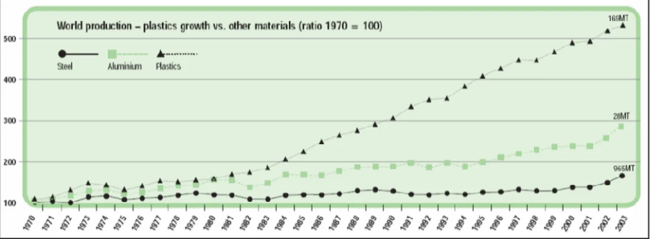
Figure 1.7: Growth of polymer production compared with steel and aluminium ... 9
Figure 1.8: Yearly polymer consumption per capita in the EU-15... 9
Figure 1.9: Development and tendency of margins for commodity polymers (e.g. polypropylene) ... 12
Figure 1.10: Development of margins for engineering plastics (e.g. PBT, POM, and PA) ... 13
Figure 1.11: Share from the GDP of the Spanish chemical industry... 18
Figure 2.1: General production scheme ... 21
Figure 2.2: Polymerisation by the opening of a double bond (e.g. ethylene) ... 23
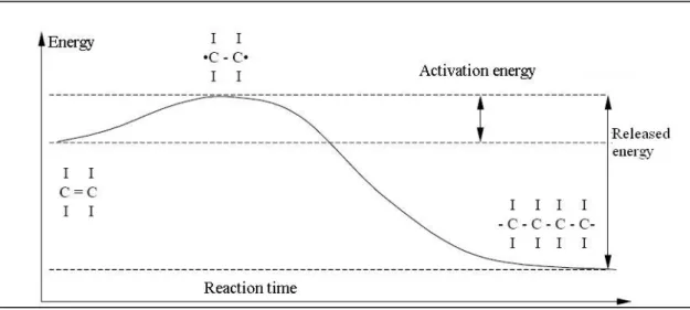
Figure 2.3: Energy curve of homopolymerisation... 24
Figure 2.4: Schematic view of a polycondensation reaction ... 25
Figure 2.5: Schematic view of a polyaddition reaction ... 26
Figure 3.1: Molecular structure of LDPE... 32
Figure 3.2: Molecular structure of HDPE ... 33
Figure 3.3: Molar mass distributions of HDPE ... 33
Figure 3.4: Molecular structure of LLDPE ... 34
Figure 3.5: Base unit of polypropylene ... 34
Figure 3.6: Molecular structures of polypropylene ... 35
Figure 3.7: Flow diagram showing LDPE production ... 40
Figure 3.8: Flow diagram of an HDPE STR ... 45
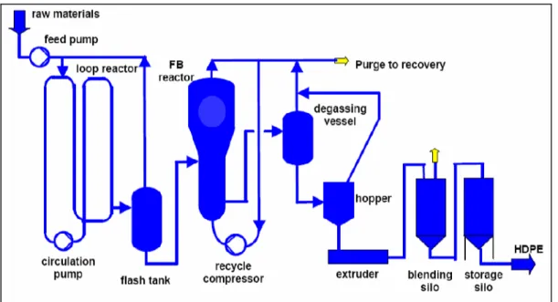
Figure 3.9: Flow diagram of an HDPE loop... 47
Figure 3.10: Flow diagram showing the HDPE gas phase process ... 48
Figure 3.11: Flow diagram showing the HDPE suspension/gas phase process... 49
Figure 3.12: Flow diagram showing the LLDPE solution process... 51
Figure 3.13: Generic flow diagram showing the traditional suspension (‘slurry’) process... 54
Figure 3.14: Flow diagram of the Spheripol polypropylene process... 55
Figure 3.15: Flow diagram of the polypropylene fluidised bed gas phase process ... 58
Figure 3.16: Flow diagram of the polypropylene vertical reactor gas phase process... 59
Figure 3.17: Flow diagram of the polypropylene horizontal reactor gas phase process... 60
Figure 3.18: Interpretation scheme for emission and consumption data in this section ... 61
Figure 4.1: Molecular structure of polystyrene ... 69
Figure 4.2: Molecular structure of high impact polystyrene ... 70
Figure 4.3: Chain propagation in the polystyrene process ... 73
Figure 4.4: Flow diagram showing the GPPS process ... 75
Figure 4.5: Flow diagram showing the HIPS process ... 79
Figure 4.6: Flow diagram showing the EPS process ... 81
Figure 5.1: Flow diagram of an S-PVC process... 96
Figure 5.2: Flow diagram of an E-PVC process... 97
Figure 6.1: Basic condensation reaction scheme for producing unsaturated polyester resins... 105
Figure 6.2: Flow diagram of the UP production process... 109
Figure 7.1: Production share of synthetic rubbers... 119
Figure 7.2: Main applications of ESBR ... 121
Figure 7.3: Flow diagram of the ESBR production process... 122
Figure 8.1. Principal flow scheme – solution polymerisation ... 131
Figure 9.1: Basic reaction of AB type polyamides... 137
Figure 9.2: Basic reaction of AA-BB type polyamides... 138
Figure 9.3: Main applications for polyamides... 138
Figure 9.4: Flow diagram of the continuous PA 6 process ... 140
Figure 9.5: Flow diagram of discontinuous PA 6 process... 141
Figure 9.6: Flow diagram of the salt concentration process for PA 66 production ... 143
Figure 9.7: Flow diagram of continuous PA 66 process ... 144
Figure 9.8: Flow diagram of the batch PA 66 polycondensation process ... 146
Figure 9.9: Flow diagram of the spinning process for textile yarns ... 148
Figure 9.10: Flow chart of the spinning process for technical yarns... 149
Figure 9.11: Flow diagram of the processing of staple fibres ... 150
Figure 10.2: Flow chart of the PET DMT process...162 Figure 10.3: Flow chart of the PET TPA process ...162 Figure 10.4: Flow diagram of continuous solid state polymerisation ...164 Figure 10.5: Schematic view of the batch solid state process...165 Figure 10.6: Flow diagram of the DMT-BPU process...166 Figure 10.7: Flow diagram of the production of spinning chips...167 Figure 10.8: Flow diagram of the spinning of staple fibres ...168 Figure 10.9: Flow diagram of the finishing of staple fibres...168 Figure 10.10: Flow chart of the production of filament yarns ...169 Figure 11.1: Flow diagram of viscose fibre production process ...175 Figure 11.2: Flow diagram of the Lyocell process ...180 Figure 12.1: Schematic view of a gear pump...203 Figure 12.2: Schematic view of the condensation of CS2from viscose fibre production...240
Figure 12.3: Schematic view of biological waste water treatment ...249 Figure 14.1: Desulphurisation and H2SO4production with double catalysis...277
List of tables
Table 1.1: Thermoplastics and thermosets consumption for Western Europe for 2001, 2002 and 2003 ... 10 Table 1.2: Plastic processors’ consumption by country, new Member States and new accession countries,
2003 ... 11 Table 1.3: Polymer consumption in New Member States and accession countries by type of plastic ... 11 Table 1.4: Raw material costs 1993 - 1999 ... 12 Table 1.5: Commodity production for EU-25 + Norway + Switzerland ... 12 Table 1.6: Production capacity for commodity plastics in 2003 for Western Europe... 13 Table 1.7: Structure of the German polymer industry in 1998... 14 Table 1.8: German commodity polymer production in 2003 ... 14 Table 1.9: Number of German producers for commodity polymers ... 15 Table 1.10: Key economic figures of the French polymer production industry in 2000... 16 Table 1.11: Basic data from the French polymer industry in 2000 ... 17 Table 1.12: Production data from the Spanish polymer industry in 2002 ... 19 Table 1.13: Belgian main polymer production data (capacities in 2003)... 20 Table 2.1: Dependency of the degree of polymerisation on the conversion rate in a step growth reaction 25 Table 2.2: Product – process matrix for some polymers ... 30 Table 3.1: Growth of polyethylene consumption ... 31 Table 3.2: Main Western European polyethylene production sites in 2001... 32 Table 3.3: Western European polypropylene production 2000 – 2002 ... 34 Table 3.4: Technical parameters of LDPE ... 42 Table 3.5: Process overview HDPE ... 43 Table 3.6: Technical parameters of HDPE... 50 Table 3.7: Technical parameters of LLDPE... 51 Table 3.8: Technical parameters of PP... 60 Table 3.9: Emission and consumption data of LDPE plants ... 62 Table 3.10: Emission and consumption data per tonne of EVA copolymer... 63 Table 3.11: Emission and consumption data of HDPE plants... 64 Table 3.12. Emission data of HDPE plants in Germany ... 64 Table 3.13: Emission and consumption data of LLDPE plants... 65 Table 3.14: Economic parameters of polyethylene production ... 67 Table 4.1: Development of worldwide polystyrene usage in Mt/yr ... 69 Table 4.2: PS (GPPS + HIPS) producers in EU-15 in 2000... 71 Table 4.3: EPS producers in the EU-15 in 2000 ... 71 Table 4.4: Technical parameters of GPPS... 76 Table 4.5: Summary of the GPPS process... 77 Table 4.6: Technical parameters of HIPS... 79 Table 4.7: Summary of the HIPS process ... 80 Table 4.8: Technical paramters of EPS ... 82 Table 4.9: Summary of the EPS process ... 83 Table 4.10: Emission and consumption data per tonne of product from GPPS plants... 84 Table 4.11: Sources of emissions in the GPPS process... 85 Table 4.12: Emission and consumption data per tonne of product of HIPS plants ... 86 Table 4.13: Sources of emissons in the HIPS process... 87 Table 4.14: Emission and consumption data per tonne of product from EPS plants... 88 Table 4.15: Sources of emissons in the EPS process ... 89 Table 5.1: Western European PVC production ... 92 Table 5.2: European production sites and capcities in kilotonnes for the year 1999... 93 Table 5.3: Typical features of E-PVC processes... 98 Table 5.4: VCM emissions according to OSPAR and ECVM ... 101 Table 5.5: Emission data from S-PVC in g/tonne as submitted by ECVM... 102 Table 5.6: Dust and VCM emissions from German S-PVC reference plants... 102 Table 5.7: Emission data from E-PVC in g/tonne as submitted by ECVM... 102 Table 5.8: Dust and VCM emissions from German E-PVC reference plants ... 103 Table 5.9: Typical energy consumption of PVC processes... 103 Table 5.10: Consumption data from the S-PVC plant... 103 Table 5.11: VCM emissions from different sources... 103 Table 5.12: Emissions to water from the S-PVC plant... 104 Table 6.1: Western European UP production 2000 - 2002... 106 Table 6.2: UP producing sites in Europe... 106 Table 6.3: Raw material overview of UP production processes... 107
Table 6.5: Good practice industry values for emission and consumption levels ...116 Table 6.6: Energy and water consumption data for UP plants...117 Table 6.7: Emission data for UP plants ...117 Table 7.1: European ESBR producers, locations and capacity...120 Table 7.2: Technical parameters of the ESBR process ...125 Table 7.3: Emission and consumption data from ESBR plants (per tonne of product) ...126 Table 8.1: production volume share of the major types of synthetic rubber...127 Table 8.2. Companies and capacities of the 15 plants in Europe producing solution rubber...128 Table 8.3 Technical parameters for typical solution plants ...135 Table 8.4. Emission levels reported from 16 plants within the EU ...136 Table 9.1: Western European polyamide production 2000 - 2002 ...138 Table 9.2: Waste water data from the manufacture of polyamide ...152 Table 9.3: Emissions and consumptions from polyamide production processes ...154 Table 9.4: Emissions and consumptions from polyamide processing ...155 Table 9.5: Emission and consumption data from the continuous PA6 production process ...156 Table 9.6: Emission and consumption data from the batch PA6 production process ...156 Table 9.7: Emission and consumption data from the continuous PA66 production process ...156 Table 9.8: Emission and consumption data from the batch PA66 production process ...157 Table 9.9: Emission and consumption data from the textile yarn process ...157 Table 9.10: Emission and consumption data from the BCF PA yarns and staple fibres processes...158 Table 10.1: European PET production 2000 - 2002 ...159 Table 10.2: Technical parameters of continuous solid state post condensation...164 Table 10.3: Technical parameters of batch solid state post condensation...165 Table 10.4: Emission and consumption data of PET producing processes...170 Table 10.5: Emission and consumption data of post condensation processes ...171 Table 10.6: Emission and consumption data of PET processing techniques ...171 Table 11.1: Emission and consumption data for viscose staple fibre production ...181 Table 11.2: Emission and consumption data for viscose filament yarn production...182 Table 12.1: Information breakdown for each technique as described in this chapter ...183 Table 12.2: Cost factors for equipment design ...192 Table 12.3: Cost situation for the implementation of a new pump ...192 Table 12.4: Efficiency and cross-media effects of VOC treatment techniques ...198 Table 12.5: Energy efficiency of cogeneration systems of different size ...202 Table 12.6: Comparison of costs for a conventional system and pigging pipeline system...207 Table 12.7: Monomer content in EVA copolymer with and without the use of devolatilisation equipment
...217 Table 12.8: Operational costs per tonne of homopolymer product (2 MFI) with (B) and without (A)
devolatilisation extrusion ...217 Table 12.9: Rating scheme for emission reduction techniques in PS processes ...222 Table 12.10: Techniques used in GPPS processes...222 Table 12.11: Techniques used in HIPS processes...223 Table 12.12: Techniques used in EPS processes ...224 Table 12.13: Techniques used in ESBR processes ...237 Table 13.1: How to combine the BAT described in this chapter for the different polymers ...253 Table 13.2: BAT associated emission and consumption levels (BAT AEL) for the production of LDPE
...259 Table 13.3: BAT associated emission and consumption levels (BAT AEL) for the production of LDPE
copolymers. ...260 Table 13.4: BAT associated emission and consumption levels (BAT AEL) for the production of HDPE
...260 Table 13.5: BAT associated emission and consumption levels (BAT AEL) for the production of LLDPE
...261 Table 13.6: BAT associated emission and consumption levels (BAT AEL) for the production of GPPS263 Table 13.7: BAT associated emission and consumption levels (BAT AEL) for the production of HIPS 264 Table 13.8: BAT associated emission and consumption levels (BAT AEL) for the production of EPS ..265 Table 13.9: BAT associated emission and consumption levels for the production of PVC...268 Table 13.10: Split view – VCM emissions related to BAT techniques ...268 Table 13.11: BAT associated emission and consumption levels for the production of UP ...269 Table 13.12: BAT associated emission and consumption levels for the production of ESBR per tonne of
product ...271 Table 13.13: BAT associated emission and consumption levels for the production of viscose staple fibres
...276 Table 15.1: Timing of the work for this document ...279
SCOPE
In Annex I to the IPPC Directive, the categories of industrial activities referred to in Article 1 of the Directive are defined. Section 4 of Annex I addresses the chemical industry. This document focuses on the production of polymeric materials in plants on an industrial scale. Specifically, this document addresses parts of the following sections from Annex 1 to the IPPC Directive: 4.1. Chemical installations for the production of basic organic chemicals, such as:
(a) basic plastic materials (polymers, synthetic fibres and cellulose-based fibres) (b) synthetic rubbers
(c) oxygen-containing hydrocarbons such as alcohols, aldehydes, ketones, carboxylic acids, esters, acetates, ethers, peroxides, epoxy resins.
The scope covers an enormous variety of produced substances. Therefore, this document describes the production of polymers selected according to production volume and potential environmental impact of their manufacture as well as availability of data, and deals with environmentally relevant unit processes and unit operations, along with the usual infrastructure found at a typical site. The present document cannot, and is not intended to replace the chemical textbooks on ‘green chemistry’ and indeed it gives only general guidance for the early stages of process design – but deals mainly with process modifications, plant operation and maintenance and especially with the management of unavoidable waste streams.
The further processing of polymers to produce final products is not included in the scope of this document. However, processing techniques such as the production of fibres or compounding are included when they are technically connected to the production of the polymer and carried out on the same site, and when they have an effect on environmental impact of the installation. The treatment of waste gas and waste water is also a subject included in this document, where sector specific conditions require this – but more in terms of applicability and performance in the polymer sectors than in terms of the technical description of individual treatment techniques. On this subject, the reader may find useful information in the BREF on ‘Common waste gas and waste water treatment/management systems in the chemical sector’.
1 GENERAL INFORMATION ON THE PRODUCTION OF
POLYMERS
[1, APME, 2002, 16, Stuttgart-University, 2000]
The most important specific terms and abbreviations used in this document can be found in the glossary at the end.
1.1 Definition
Polymers – from Greek ‘poly’ (many) and ‘meros’ (parts) – are a group of chemical products which have a common building principle. They consist of so-called macromolecules which are long chain molecules, containing large numbers of smaller constitutional repeating units. Molecules consisting of a small number of monomers often are called ‘oligomers’ which means ‘some parts’.
There are different types of polymers: natural polymers (for example wool, silk, wood, cotton), half synthetic polymers (natural polymers which are chemically modified, for example casein plastics, cellulose plastics) and synthetic polymers [27, TWGComments, 2004].
Monomers which mostly belong to the group of large volume organic products are nowadays usually produced from petrochemical feedstock (crude oil or gas). Exemptions are the cellulosic materials which are produced from cotton or wood fibres or biodegradable products produced from renewable raw materials.
1.2 Structure
Macromolecules can be linear or branched (containing sidechains) and may be cross-linked, linking one chain with another. Examples of these three types of macromolecules are shown in Figure 1.1.
Figure 1.1: Basic structures of polymers A) linear polymer
B) branched polymer
Polymers can be composed from just one type of monomer (homopolymer) or from different types (copolymer). In the case of a linear copolymer consisting of two different monomers (e.g. A and B), the different monomers can basically be arranged in three different ways:
• random copolymer: there is no regularity in the arrangement of the two different monomers in the polymer
• block copolymer: blocks of pure A oligomer alternate with blocks of pure B oligomer
• alternating copolymer: the monomers A and B alternate within the composition of the polymer.
The composition and arrangement of the different monomers in a copolymer strongly influences its physico-chemical properties. Figure 1.2 shows the structure of a linear homopolymer and the three types of linear copolymer mentioned above.
Figure 1.2: Chemical composition of linear AB copolymers. 1) homopolymer
2) random copolymer
3) block copolymer
4) alternating copolymer
Apart from the linear copolymers, branched coploymers can be produced by grafting sidechains (consisting of monomer B) onto an existing homopolymeric mainchain (consisting of monomer A) (Figure 1.3).
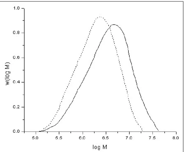
The polymerisation reactions are statistically driven processes. Therefore, unlike some natural polymers such as DNA, synthetic polymers always show, due to the reaction mechanisms involved in the production processes, a certain distribution of molar mass and not a distinct molecular weight. The molar mass of synthetic polymers can range from some thousand g/mol up to some million g/mol. As an example, Figure 1.4 shows the normalised molar mass distribution (MMD) curves of two different polyethylene samples.
Figure 1.4: Normalised molar mass distribution curves of two different polyethylene samples [29, M. Parth, et al., 2003]
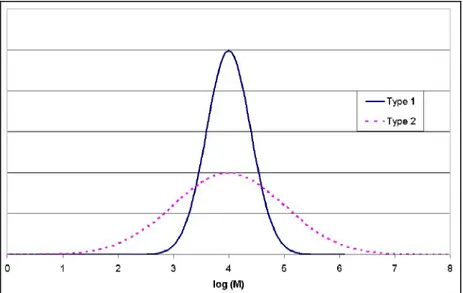
Apart from molar mass and chemical composition, the properties of a polymeric material can be influenced by the shape of the MMD. The samples shown in Figure 1.4 both show a unimodal MMD, but to achieve some special mechanical properties, in some cases it is necessary to produce polymers with bimodal or multimodal MMD, as in natural polymers such as natural rubber (NR). This can be achieved by two subsequent polymerisation steps.
1.3 Properties
1.3.1 General
properties
The underlying building principle is very flexible so that polymers with an extensive range of properties and property combinations can be produced. Polymers in the shape of objects, fibres or films may be:
• rigid or flexible
• transparent, translucent or opaque
• hard or soft
• weather resistant or degradable
• resistant to either high or low temperature.
In addition, they may be compounded with fillers, blended with other products (e.g. glass fibres) forming so-called composites or with other polymers yielding polymer blends.
A certain polymer is usually not the only material which can be used in any given field of application. Alternative materials exist and polymers have to be successful in a competitive market. Polymers often bring advantages to numerous applications, for example:
• weight reductions and consequent transport and fuel savings
• electrical insulating properties suitable for wiring, switches, plugs, power tools and electronics
• optical transparency suitable for packaging, lighting and lens applications
• corrosion resistance which is important for plumbing, irrigation, rainwear and sports articles
• resistance to chemicals, fungi and mildew
• ease of processing making complicated shapes possible
• cost savings over alternative solutions.
1.3.2 Thermal
properties
Usually, substances can exist in three possible physical states: solid, liquid and gas. In polymeric materials, things are not so straightforward. For example, most polymers will decompose before they boil, and cross-linked polymers decompose before they melt.
According to their basic thermal properties, four different types of polymers are distinguished.
1.3.2.1 Thermoplastics
Thermoplastics are polymeric materials, which are more or less rigid at room temperature and can be melted by heat.
1.3.2.2 Thermosets
Thermosets are also rigid at room temperature, but due to the cross-links in their molecular structure, they cannot be melted.
1.3.2.3 Rubbers or elastomers
Rubbers are flexible at room temperature. Most of them are amorphous materials and do not show a melting point. They have a glass transition point instead which is well below room temperature. Below this glass transition temperature they are rigid.
1.3.2.4 Thermoplastic elastomers
Thermoplastic elastomers are block copolymers or polymer blends that are flexible and show properties similar to vulcanised rubbers at room temperature, but which can be softened or melted by heat. This process is reversible, so the products can be reprocessed and remoulded.
1.4 Main
uses
1.4.1
Fields of application
Polymeric materials are used in simple household items like plastic bags as well as in advanced optical or electronic components or in medical applications. The main fields of application for Western Europe are shown in Figure 1.5. which does not include data about elastomers and cellulosic fibres. For 2003, the total amount of consumed thermoplastics and thermosets in Western Europe was 48788 kilotonnes.
1.4.2 Processing
technologies
A range of processing technologies are used to convert raw polymers into the required shape of the final product. This conversion step is normally entirely separate from the manufacturing site of polymer pellets. The processing step itself is mainly a physical transformation step using different technologies such as:
• extrusion for pipes, profiles, sheets and cable insulation
• injection moulding for products of different, often very complex shapes like machine parts, electrical plugs and medical equipment such as syringes; thermoplastics and thermosets
• blow moulding for bottles, containers and films
• calendering for films and sheeting
• rotomoulding for large shapes
• pultrusion for rods, tubes, etc.
• blown film for thermoplastics
• cast film for thermoplastics
• coating for thin layers on different substrates
• pressing for resins
• spinning for fibres
• transfer moulding for thermosets
• compression moulding for thermosets
• vulcanisation for rubbers
• blending generally applicable technique.
Usually, chemical reactions do not occur during these processing steps, except during the vulcanisation of rubber, during the in-process cross-linking of certain types of cable insulations made from polyethylene and when processing certain resins with in-situ polymerisations. Such special processing steps are described in literature [14, Winnacker-Kuechler, 1982].
1.5 Main
products
1.5.1
Polymers based on crude oil
Different market requirements have resulted in a wide range of polymeric materials which are grouped into:
structural materials where the polymer is the main and most visible structural component with the subgroups:
• commodity polymers (polyethylene, polypropylene, polystyrene, polyvinyl chloride, ESBR, etc.). Such polymers are used in large quantities at relatively low costs for major applications like tubes, films, profiles, containers, bottles, sheets, tyres, etc.
• engineering polymers and speciality rubbers (ABS, polyamides, polyesters, polyacetals, polymethyl methacrylates, EPDM, NBR, etc.). Such polymers are used for special requirements at an intermediate cost level often for very small parts (clips, valves, special machine parts, etc.)
• high performance products (polyimide, polytetrafluoroethylene, polysulfone, polyetherketone, fluorinated and silicone rubbers, etc.). Such low volume, high priced materials are used to meet extreme requirements like high temperature, weather or solvent resistance, special wear or optical properties, extreme purity for critical medical applications, etc.)
• thermosetting polymers (polyesters, epoxies, phenolics and alkyd resins) often used as coating resins and binders for fibrous reinforcements in a range of applications from boats to brake linings.
and functional materials where polymers are used as an aid to achieve a special function. They mostly constitute a small and often invisible part of the total system only with the following subgroups:
• commodity applications like dispersants, detergents, flocculants, thickeners, superabsorbers or adhesives and glues. Here, large volume polymers based on polyvinyl acetate, polyacrylic acid and its derivatives, and polyvinyl alcohol are used
• special technical applications like membranes, optical fibres, products with electrical conductivity, and light emitting products. Here, high priced materials are used in small amounts where the functionality, and not predominantly the mechanical properties, is important.
A classification of thermoplastic products (not including elastomers and thermosetting resins) is shown in Figure 1.6. Amorphous Crystalline Commodity plastics Engineering plastics Speciality polymers P ri ce an d p er fo rm an ce Incr ea se in v o lu m e (t/ yr ) PS PVC SAN PE-LD PE-HD PP
SMA ABS PMMA
ASA PPO/PS PC PET PA6-6,6 POM PVDF PPSPA 12 PA 11 PTFE PEEK PVDC PES PEI PPS PI
Figure 1.6: Classification of thermoplastic polymers
Generally, amorphous polymers have a disordered structure, have a softening point and are very often transparent, while crystalline polymers have an ordered structure, have a softening and a melting point and are mostly opaque.
Amongst the polymers based on crude oil, seven groups of polymers – polyolefins (PE and PP), polystyrene (PS), polyvinyl chloride (PVC), polyethylene terephthalate (PET), emulsion polymerised styrene butadiene rubber (ESBR), polyamides (PA) and unsaturated polyester resins (UP) constitute approximately 80 % of the total consumption of polymers.
Within each product group, there exists a wide variety of individual product grades optimised for the specific application (tailor-made).
For example:
• PE with good flow properties for injection moulding or, for instance, boxes or containers
• PE with excellent long-term stability for pipes
• PE with good blow moulding properties for petrol tanks in automobiles.
They are not interchangeable for these specific applications. Some have a low molecular weight; some have a high molecular weight, and while some have a narrow molecular weight distribution, others offer an extremely wide molecular weight distribution. The final mechanical, rheological and other physical properties depend on these parameters.
1.5.2
Polymers based on renewable resources
Historically, the first polymers were produced from renewable resources:
• fibres from cellulose (cotton) or derivatives (cellulose acetate)
• fibres from polypeptides (wool)
• plastics from cellulose acetate
• rubber from tree resin (polyisoprene).
While some of these products stayed competitive (rubbers, viscose fibres), others – especially in the field of thermoplastic material applications – did not, mainly for economic reasons or insufficient properties but sometimes also due to high environmental costs.
Newer attempts to develop wood-based plastics (‘synthetic wood’) remained limited to niche applicati

![Figure 3.15: Flow diagram of the polypropylene fluidised bed gas phase process [15, Ullmann, 2001]](https://thumb-us.123doks.com/thumbv2/123dok_us/76349.2508666/84.892.84.728.76.414/figure-flow-diagram-polypropylene-fluidised-phase-process-ullmann.webp)
![Figure 3.16: Flow diagram of the polypropylene vertical reactor gas phase process [15, Ullmann, 2001] A) primary reactor B) copolymeriser C) compressors D) condensers E) liquid pump F) filters G) primary cyclone H) deactivation/purge](https://thumb-us.123doks.com/thumbv2/123dok_us/76349.2508666/85.892.207.761.76.458/figure-polypropylene-vertical-ullmann-copolymeriser-compressors-condensers-deactivation.webp)
![Figure 3.17: Flow diagram of the polypropylene horizontal reactor gas phase process [15, Ullmann, 2001]](https://thumb-us.123doks.com/thumbv2/123dok_us/76349.2508666/86.892.104.708.77.410/figure-flow-diagram-polypropylene-horizontal-reactor-process-ullmann.webp)
