Effect of Tempering on Cyclic Loading of Medium Carbon
Steel
A thesis submitted in partial fulfilment of the
requirements for the degree of
Master of Technology
in
Mechanical Engineering
[Steel technology]
By
Gaurav Kumar Gupta
Roll No- 213MM2482
Department of Metallurgical and Materials Engineering
National Institute of Technology
Rourkela-769008
May 2015
Effect of Tempering on Cyclic Loading of Medium Carbon
Steel
A Thesis submitted in partial fulfilment of the requirements for the degree of
Master of Technology
in
Mechanical Engineering
[Steel technology]
By
Gaurav Kumar Gupta
Roll No- 213MM2482
Under the Guidance of
Prof. Sudipta Sen
Metallurgical & Materials Engineering Department National Institute of Technology
Rourkela -769008
Department of Metallurgical and Materials Engineering
National Institute of Technology
Rourkela-769008
May 2015
Department of Metallurgical and Materials Engineering
National Institute of Technology
Rourkela- 769008
CERTIFICATE
This is to certify that the work in this thesis report entitled “Effect of Tempering on Cyclic Loading of Medium Carbon Steel” which is being submitted by Mr. Gaurav Kumar Gupta, National Institute of Technology, Rourkela has been carried out under my guidance and supervision in partial fulfilment of the requirements for t h e d e gr e e of M a s t e r o f T e c h n o l o g y in M e c h a n i c a l Engineering (Steel technology) and is bonafide record of work.
To the best of my knowledge, the matter embodied in the thesis has not been submitted to any other University / Institute for the award of any Degree or Diploma.
Prof. Sudipta Sen
Date: Dept. of Metallurgical and Materials Engineering
Place: NIT, Rourkela National Institute of Technology
ACKNOWLEDGEMENT
With deep regards and profound respect, I avail this opportunity to express my deep sense of gratitude and indebtedness to Prof. Sudipta Sen, Associate Professor, Department of Metallurgical and Materials Engineering for introducing the present research topic and for his inspiring guidance, constructive criticism and valuable suggestion throughout in this research work. It would have not been possible for me to bring out this thesis without his help and constant encouragement.
I am sincerely thankful to Prof. S. C. Mishra, Head, Department of Metallurgical and Materials Engineering, for his advice and providing necessary facility for my work.
I would also like to thank Prof. P. K. Ray, Department of Mechanical Engineering for his help.
Special thanks to Mr. Rajesh Pattnaik, Mr. Hembram, of the department for being so supportive and helpful in every possible way.
I am highly grateful to all staff members of Department of Metallurgical and Materials Engineering, NIT Rourkela, for their help during the execution of experiments and also thank to my well wishers and friends for their kind support.
Contents
Abstract ... i List of figures ... ii List of tables... vi Chapter 1 ... 1 Introduction ... 1 Chapter 2 ... 3 Literature review ... 3 2.1 Introduction to Steel ... 4 2.2 Classification of Steel ... 42.2.1 Plain Carbon Steel ... 5
2.2.2 Kinds of Plain Carbon Steel ... 6
2.2.3 Alloy steels ... 11
2.2.4 Effects of alloying elements ... 11
2.3 Heat Treatment ... 13
2.3.1. Annealing ... 16
2.3.2. Normalizing ... 17
2.3.3. Quenching and Tempering ... 17
2.4. Fatigue of steel ... 19 2.4.1. Fundamentals of Fatigue ... 20 2.4.2. Stress Cycles ... 21 2.4.3. S-N Curve ... 22 2.4.4. Fatigue Mechanism ... 23 Chapter 3 ... 25 Experimental Techniques ... 25 3.1. Specimen preparation ... 27
3.2. Heat treatment (quenching and tempering) ... 28
3.3. Investigation of Mechanical properties ... 29
3.3.1 Hardness test ... 30
3.3.2 Tensile test ... 30
3.4. Microstructural analysis and Fractographical studies ... 32
3.5. Fatigue test ... 33
Chapter 4 ... 35
Results and discussions ... 35
4.1 Introduction ... 36
4.3 Mechanical properties ... 39
4.3.1 Hardness test ... 39
4.3.2 Tensile test results ... 42
4.4 Fractographical studies after tensile test. ... 53
4.5 Fatigue life estimation ... 54
4.6 Fractographical studies after fatigue test ... 63
Chapter 5 ... 65
Conclusion ... 65
5.1 Conclusion ... 66
i
Abstract
The utility of Medium Carbon steel is well known now-a-days. It has got such a variety of uses in distinctive commercial ventures because of its moderately low cost and great mechanical properties. The failure due to cyclic loading or dynamic loading is a crucial topic in the field of mechanical behaviour of materials since cyclic loading counts about ninety percent of the failures resulted from mechanical causes. In this work the cyclic loading behaviour of Medium Carbon Steel has been studied. The properties of steel are greatly influenced by various heat treatment techniques and tempering is the most common and important heat treatment technique. In the present work the effect of tempering on microstructure, tensile properties, hardness and most importantly on cyclic loading behaviour has been studied. The emphasis is given to the endurance limit. Attempts have been made to find out the best set of tempering conditions. The Medium Carbon Steel specimens were first austenitized at 850oC, hold for 1hr for soaking and then quenched in water bath maintained at room temperature. The quenched specimens were then tempered at three different temperatures 200oC, 400oC and 600oC the duration of tempering treatment was 60min., 90min., and 120min. for all of the above temperatures. Attempts have been made to correlate the microstructure with the mechanical properties of Medium Carbon Steel.
The cyclic loading test was carried out in R.R. Moore Rotating Beam Testing Machine with a completely reversed stress pattern. Here the maximum stress and minimum stress are equal in magnitude but opposite in sense so the stress ratio i.e. the ratio of maximum stress to minimum stress becomes R= -1, the mean stress becomes zero.
From this work, it may be concluded that tempering significantly improves the mechanical properties as well as the fatigue life of the material, and the best results have been seen for low temperature tempering at 2000C, for 60 min.
ii
List of figures
Page no.
Fig 2.1 Classification of Steels (Lovatt and Shercliff, 2002) 5
Fig 2.2 Classification of plain carbon steel 7
Fig 2.3 SEM micrographs of the microstructure of 0.05%wt C steel 8
ferrite(dark) andpearlite(light)
Fig 2.4 Optical micrograph of 0.4% wt. Carbon steel in 1100X .. 9
Fig 2.5 Optical micrograph of a 0.8% wt. carbon steel in 1000X. 10 Fig 2.6 (a) Microstructure of AISI 1020 Steel (Etching: Nital 0.3%)
(b) Microstructure of the AISI 1020 Steel heat treated at 750 0C
for 150 min. 13
Fig 2.7 Iron-Carbon Phase Diagram 14
Fig 2.8 Microstructure of 1045 Steel Bar 16
Fig 2.9 Heat Treated Microstructures 19
Fig 2.10 Different types of Fatigue Fractures 20
Fig 2.11 Stress Cycles (a) Completely Reversed loading,
(b) Repeated loading, and (c) Random loading 21
Fig 2.12 Typical Fatigue Curve for Ferrous and Non-Ferrous materials 22
Fig 2.13 Slip Mechanism 24
Fig 3.1 Experimental layout 26
Fig 3.2 Specimen specification for fatigue and tensile test 28
iii
Fig 3.4 Optical microscope. 32
Fig 3.5 Scanning electron microscope (SEM) 32
Fig 3.6 R.R. Moore rotating beam testing machine.
33
Fig 4.1 Optical micrograph of as-received specimen (medium carbon steel) in 200X 37
Fig 4.2 Optical micrograph of medium carbon steel tempered at 2000C
(a) 100X, (b) 200X. 37
Fig 4.3 Optical micrograph of medium carbon steel tempered at 4000C
(a) 100X, (b) 200X. 38 Fig 4.4 Optical micrograph of medium carbon steel tempered at 6000C
(a) 100X, (b) 200X 38
Fig 4.5 Comparison of hardness between as-received
and tempered conditions 40
Fig 4.6 Comparison of hardness between different tempering
conditions. 41
Fig 4.7 Engineering stress vs. strain curve, Tempering at 2000C, 60 min. 42
Fig 4.8 Engineering stress vs. strain curve, Tempering at 2000C, 90 min. 42
Fig 4.9 Engineering stress vs. strain curve, Tempering at 2000C, 120 min. 43
Fig 4.10 Engineering stress vs. strain curve, Tempering at 4000C, 60 min. 44 Fig 4.11 Engineering stress vs. strain curve, Tempering at 4000C, 90 min. 44
Fig 4.12 Engineering stress vs. strain curve, Tempering at 4000C, 120 min. 45
Fig 4.13 Engineering stress vs. strain curve, Tempering at 6000C, 60 min. 46 Fig 4.14 Engineering stress vs. strain curve, Tempering at 6000C, 90 min. 46 Fig 4.15 Engineering stress vs. strain curve, Tempering at 6000C, 120 min. 47
iv
Fig 4.16 Comparison of Yield stress between as-received and tempered
conditions. 49 Fig 4.17 Comparison of Yield stress between differently tempered
conditions 49 Fig 4.18 Comparison of Ultimate tensile stress between as-received and
tempered conditions 50
Fig 4.19 Comparison of Ultimate tensile stress between differently
tempered conditions 50
Fig 4.20 Comparison of % Elongation between as-received and
tempered conditions 51
Fig 4.21 Comparison of % Elongation between differently tempered
conditions 51
Fig 4.22 Fractograph after tensile test, 2000C Tempering,
(a) 2000X, (b) 3000X 53
Fig 4.23 Fractograph after tensile test, 4000C Tempering,
(a) 2000X, (b) 3000X 53
Fig 4.24 Fractograph after tensile test, 6000C Tempering,
(a) 2000X, (b) 3000X 54
Fig 4.25 S-N Curve, Tempered at 200 0C, 60 min. 55
Fig 4.26 S-N Curve, Tempered at 200 0C, 90 min. 55
Fig 4.27 S-N Curve, Tempered at 200 0C, 120 min. 56
Fig 4.28 S-N Curve, Tempered at 400 0C, 60 min. 56
Fig 4.29 S-N Curve, Tempered at 400 0C, 90 min. 57
v
Fig 4.31 S-N Curve, Tempered at 600 0C, 60 min. 58
Fig 4.32 S-N Curve, Tempered at 600 0C, 90 min. 58
Fig 4.33 S-N Curve, Tempered at 600 0C, 120 min 59
Fig 4.34 Comparison of fatigue limit between differently tempered
conditions. 59 Fig 4.35 (a)S-N curves for tempering at 2000C, for different time durations. 60
(b)S-N curves for tempering at 4000C, for different time durations. 60
(c)S-N curves for tempering at 6000C, for different time durations. 61 4.36 (a), (b), and (c)Fractograph of specimens after fatigue tests 63
vi
List of tables
Page No.
Table 2.1 Percentage of Weight of Residual Elements in Plain Carbon Steel 6
Table 2.2 Standard Mechanical Properties of Low-Carbon Steel 8
Table 3.1 Composition of specimen 27
Table 4.1 Results of Hardness test 39
Table 4.2 Tensile properties of as-received and differently tempered
1
Chapter 1
2
Introduction
It has been observed by the researchers way back in around 1850, that a material fails at a lower stress when subjected to cyclic or dynamic loading, as compared to the stress required for failure in static loading. Scientists used the term fatigue to indicate a cyclic or dynamic loading. Also it has been found that 90% of the failures occurred due to mechanical reasons are resulted from fatigue. Hence, from research point of view the fatigue failure becomes a very important topic. Since the discovery of fatigue many researchers have conducted different works to study different aspects of failure due to fatigue or cyclic loading and to improve the fatigue life of the materials.In this work the effect of Tempering (at different temperatures and different time durations) on cyclic loading of medium carbon steel has been studied. The steel is a very useful and important material used in different engineering application, and the medium carbon steel is the most commercially used steel. For this work the material selected is the medium carbon steel (0.524% Carbon by wt.), because medium carbon steel has good mechanical properties such as high strength and toughness. Also the properties of medium carbon steel are greatly influenced by various heat treatment techniques and tempering is most common amongst them. The change in microstructure, variation in mechanical properties and fatigue life due to different tempering conditions has been studied in this work.
Attempts have been made to get the relation between microstructure of medium carbon steel and the mechanical properties. Fractographical studies of specimens after tensile and fatigue tests have been carried out in a scanning electron microscope (SEM). Also attempts are made to correlate the tensile properties of the medium carbon steel with the endurance limit.
3
Chapter 2
4
Literature review
2.1 Introduction to Steel
Steel is an interstitial solid solution of carbon in iron with a maximum carbon content of 2.1% by weight [1]. Steel is a crucial alloy which finds its vast application in different industries and structures. In most recent twenty years, there have been tremendous advances in steelmaking process. Which makes steel most versatile and essential material. The properties of steel can be altered by different heat treatment techniques to suit the requirements. The microstructure can be related with the mechanical properties of steel and the microstructure of most of the steels are well known.
Lacktin [1] studied that carbon goes into the interstitial space in the iron and due to size of carbon atom it is the only useful material to make solid solution with iron to form an alloy. Also by varying the amount of carbon in steel the properties like ductility, hardness, and strength can be altered. An increase in percentage of carbon gives more hard material with increased strength [2].
In steel some other elements such as Molybdenum, Silicon, Cobalt, Copper, Phosphorus, Sulphur, Chromium, Manganese etc. may present and termed as alloying elements. The variation in amounts of these alloying elements can alter the properties of steel significantly. The steel which has only carbon as alloying element is called Plain Carbon Steel.
2.2 Classification of Steel
On the basis of alloying conditions the steel can be classified as: Plain Carbon Steels and alloy steels. Further the plain carbon steel are subdivided into Low Carbon Steels (mild steel), Medium Carbon Steels, and High Carbon Steels.
5
There are a variety of alloy steels properties of which depends upon the alloying elements added to the steel. Fig. 1 shows the classification of steels.
Fig 2.1: Classification of Steels (Lovatt and Shercliff, 2002)
2.2.1 Plain Carbon Steel
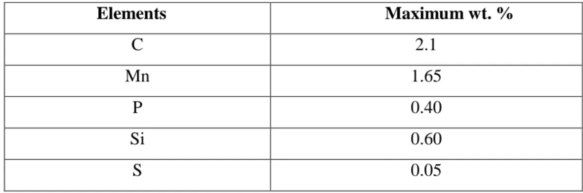
Plain carbon steel is a solid solution of carbon in iron. In considerably low amounts some other elements are also present in Plain Carbon Steel. According to AISI (American iron and steel institute) Plain Carbon Steel should contain less than 1.65% weight Mn, a maximum of 0.6% weight Si, and lower than 0.6% weight Cu. The Carbon content controls the property of steel, an increase in carbon content increases the hardness as well as strength of the steel at the cost of loss of ductility and weldability. Also high carbon content generally decreases the melting point of steel and impairs the temperature resistance [3].
The Plain Carbon Steels contain a maximum carbon content of 2.1% by wt. in addition to some more elements such as silicon, vanadium, cobalt, phosphorus, molybdenum, tungsten, nickel,
Steel
Alloy Steel Carbon Steel
Low Carbon Steel Medium Carbon
6
titanium etc. The carbon content plays an important role in deciding the properties in these steels and other elements have a lower influence on properties comparatively. The maximum weight % of elements in plain carbon steel are shown in Table 2.1
Table 2.1: Percentage of Weight of Residual Elements in Plain Carbon Steel Elements Maximum wt. % C 2.1 Mn 1.65 P 0.40 Si 0.60 S 0.05
Advantages of Plain Carbon Steel
- Significant weldability and formability. Ductile and tough.
Good wear resistance.
Disadvantages of Plain Carbon Steel
- Low hardenability.
Loss of physical properties (strength and embrittlement) by both high and low temperatures and subject to corrosion in most environments.
2.2.2 Kinds of Plain Carbon Steel
Based on carbon percentage the plain carbon steel can be categorised in three different groups as shown in figure 2.2
7
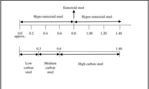
Fig. 2.2 Classification of plain carbon steel
Low carbon steel
Low Carbon Steel contains maximum carbon of 0.3% by weight. Low carbon steel is refined in basic oxygen or open hearth furnace. Low carbon steel lacks in tensile strength but possesses good ductility. Low carbon steel finds its application in forging works, riveting, and making low strength machine parts. To improve tensile strength, dimensional tolerances, and surface finish low carbon steels are cold rolled between polished rollers under very high pressure and the product is called cold rolled steel.
Akay S.K. et al. [4] studied the microstructure of 0.05% wt. carbon steel as shown in fig. 2.3 which has ferrite and pearlite matrix. The dark areas show ferrite and light areas represent pearlite. The pearlite is uniformly distributed in ferrite matrix as irregular shaped volumes. The Fraction of ferrite is very large as compared to pearlite. Ferrite being a softer phase gives significant ductility to the low carbon steel.
0.0 0.2 0.4 0.6 0.8 1.00 1.20 1.40 Hypo-eutectoid steel Hyper-eutectoid steel
Eutectoid steel approx. 0.3 0.6 1.40 Low carbon steel Medium carbon steel
8
Fig. 2.3: SEM micrographs of the microstructure of 0.05%wt C steel ferrite(dark) and pearlite(light) [4].
The standard mechanical properties of low carbon steel is given in table 2.2.
Table 2.2 Standard Mechanical Properties of Low-Carbon Steel (Everett, 1994)
Properties of Low Carbon Steel Value (Unit)
Young‟s Modulus, E 209 GPa
Yield Strength 215 – 250 MPa
Tensile Strength 400 – 500 MPa
Elongation 23%
Medium carbon steel
Medium carbon steel is more strong and tough as compared to low carbon steel. The carbon content varies between 0.3% and 0.6% by weight. Medium carbon steel is difficult to weld, bend, and cut as compared to low carbon steel. It is the most commercially used steel. Medium carbon steel possesses good strength and toughness.
9 0.3-0.4 Axles, lead screws, connecting rods, spindles, drop forging, worms.
0.4-0.5 Gears, rails, tool shanks, boilers, machine parts.
0.5-0.6 sledges, hammers, laminated springs, wire ropes.
Medium carbon steel can be heat treated to get different combinations of properties. Attention of many researchers is focused in this area. Different heat treatments have been studied on medium carbon steel such as annealing, normalizing, and quenching followed by tempering.
The microstructure of Medium carbon steel suggests that it has more amount of pearlite as compared to the amount of pearlite in low carbon steel [5]. The optical micrograph of medium carbon steel is shown in fig. 2.4 the light areas show ferrite and dark areas show pearlite.
Fig. 2.4 Optical micrograph of 0.4% wt. Carbon steel in 1100X [5].
In this work, Medium carbon steel with 0.524% carbon is to be studied for fatigue response, the further studies will be discussed in the upcoming chapters.
High carbon steel
The plain carbon steel having a carbon content between 0.6% and 1.40% by weight is known as High carbon steel. High carbon steel is very hard and generally used in cutting applications. Typical uses of High carbon steel
10 0.6-0.7 screw drivers, table knives, drop hammer dies.
0.7-0.8 anvil faces, band saws, shear blades.
0.8-0.9 cold chisels, springs, rock drills, threading dies.
0.9-1.0 hacksaw blades, taps, small punches, needles.
1.0-1.30 ball bearings, circular tools, twist drills, turning and planning tools.
1.30-1.40 Surgical instruments, razors, boring tools, fine cutters.
The microstructure of a High carbon steel containing 0.8% wt. carbon is shown in fig. 2.5. It is a eutectoid composition and hence pearlite is only phase present.
Fig 2.5 Optical micrograph of a 0.8% wt. carbon steel in 1000X.
Advantages of High carbon steel
High hardness and wear resistance
Good formability.
Disadvantages of High carbon steel
Less tough and brittle
11
2.2.3 Alloy steels
When steel is combined with one or more other elements, alloy steel is formed. Usually metallic elements are added to the steel. These elements are intentionally added to steel to obtain desired properties which are not possible to achieve in plain carbon steels. Generally alloying is done to improve following properties:
1. Corrosion resistance 2. Wear resistance 3. Hardenability 4. Machinability
5. Strength and hardness at high temperature.
The alloy steels are also heat treated to alter the properties as required. The important elements which are added to form alloy steels are Chromium, vanadium, manganese, Nickel, Tungsten, cobalt, and molybdenum.
2.2.4 Effects of alloying elements
The different alloying elements have different effects on properties of steels. Effects of some important alloying elements is discussed in following paragraphs:
Nickel
Nickel improves the corrosion resistance of steel. Nickel and chromium together are used to make stainless steels. It also increases strength and toughness to some extent. Steel with Nickel is significantly hard. It adds some elasticity to the material and the response to vibration and wear is improved. Used to make wire ropes, axles, rails etc.
12
Chromium hardens the steel and increases its toughness. It makes the steel rust resistance by making grains finer. It is the main alloying element of stainless steel, stainless steel contains about 11-25% chromium. Chromium is used to make steel for rock crushers and bearings.
Cobalt
The main application of cobalt is in making cutting tools. The important property of cobalt is that it improves the red hardness or the hardness at high temperature of the alloy. Wear resistance is also improved by use of cobalt.
Manganese
Manganese is very hard and brittle metal it makes. It adds toughness to the steel. Manganese makes steel so hard to cut and generally these steels are cast shaped. Alloy steel formed by adding Manganese is used in Jaws of rock crushers, chains, gears etc.
Molybdenum
Molybdenum increases strength and hardness of steel. The important property is, it improves the heat and shock resistance. The application of these alloys are in automobile parts and bearings.
Tungsten
Tool steels, High speed steels, and cemented carbide are made by Tungsten as an alloying element. Tungsten makes the alloy hard and increases the melting point. It allows the alloy to withstand heat. These steels are also used in armor plates.
Vanadium
Vanadium makes steel shock resistance. Vanadium makes the steel tough, increases the strength and corrosion resistance. Due to good damping properties these steels are used in springs, automobile gears and axles.
13
2.3 Heat Treatment
Heat treatment is an important tool by which the properties of the steels can be altered depending on the requirement. By distinct heat treatment processes a steel with wide range of properties can be made [6]. Heat treatment is the process of heating and cooling of materials in controlled atmosphere to alter their mechanical and physical properties as per the work requirements. The heat treatment processes is carried out in following three stages:
1. Heating the material to a required temperature 2. Holding at this temperature for soaking
3. Cooling at different rates to get different physical and mechanical properties.
Microstructural change, phase change and crystallographic change occurs during the heat treatment process [7]. Fig. 2.6 shows the microstructural variation of AISI 1020 steel before and after heat treatment at 7500C for 150min. air cooled.
Fig 2.6 (a) Microstructure of AISI 1020 Steel (Etching: Nital 0.3%)
14
The carbon steels are heat treated to get different combination of mechanical properties such as ductility, toughness, hardness, tensile strength, impact strength etc. Heat treatment processes have less impact on properties like corrosion resistance and thermal conductivity. In steels, depending upon the heat treatment process different microstructures such as ferrite and pearlite, martensite, tempered martensite, and bainite can be obtained. Martensite is a very hard and brittle phase and generally has no application so the martensitic steels are usually tempered at relatively low temperatures to retain some ductility and toughness.
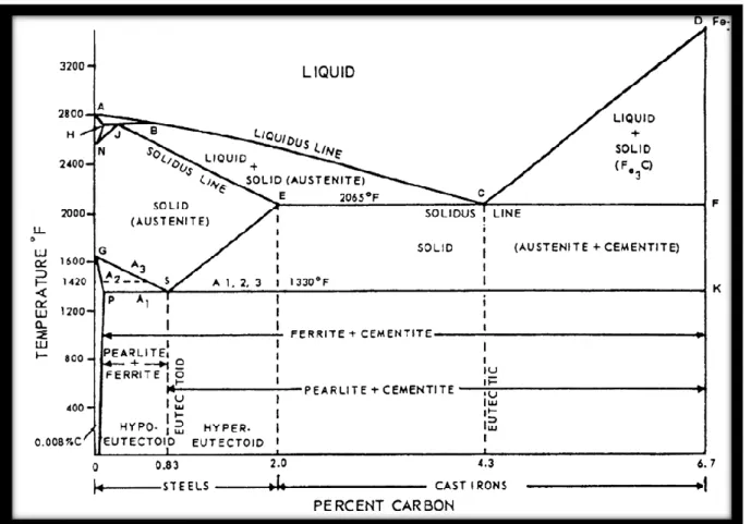
When subjected to carbon steels, before going for a heat treatment process one should precisely know the temperature, composition and other parameters. The temperature for the heat treatment is decided by the Iron-carbon equilibrium diagram given that the composition of carbon steel is well known. Fig. 2.7 shows the Iron-carbon diagram.
15
It is well known that iron is an allotropic material (it can exist in more than one lattice structure depending upon temperature). In Fig 2.7, it can be seen that at 28000F when iron solidifies, the iron in body centred cubic delta ()-ferrite form [6]. On further cooling to a temperature of 25540F, again phase change occurs and the atoms rearrange themselves into the f a c e c a n t e r e d c u b i c gamma () form, which is non-magnetic. Again, on cooling up to a temperature of 1666 0F, phase change occurs from face centred non-magnetic g a m m a ( iron to body-centred non-magnetic iron. Finally, the iron becomes magnetic without a change in lattice structure at a temperature of 1414 0F called Curie temperature.
The carbon composition is responsible for variation in the temperature at which allotropic changes occur. The iron-carbon alloy system is shown in the figure Fig 2.5. It is that part between pure iron and iron-carbide (cementite), containing 6.67% carbon by weight. This diagram is not a true equilibrium diagram, since equilibrium means phase will not change with time. It is a fact that the cementite will decompose into iron and carbon (graphite). This decomposition is a very long process at room temperature, and even at 1300 0F it will take several years to form graphite. Cementite is a metastable phase. Therefore, this diagram rightly can be called an iron-cementite diagram instead of iron-carbon diagram. The plain carbon steel having less than 0.8% carbon by wt. has a ferrite-pearlite structure [8]. On quenching martensite will be formed and tempered martensite is obtainable by quenching and tempering. Fig. 2.8 shows microstructure of a 0.45% carbon steel.
16
Fig 2.8 Microstructure of 1045 Steel Bar [9] 2.3.1. Annealing
Annealing is a heat treatment process which is used in order to obtain some amount of softness in material and to refine the grains. Annealing generally consists of three stages:
1. Heating to a specific temperature 2. Soaking for sufficient time
3. Slow cooling (usually in furnace).
Carbon steels are generally heated to upper critical temperature to form austenite, the soaking time is given to homogenise austenite grains.
Spherodizing
The main purpose of this heat treatment is to induce significant softness in high carbon steels. Spherodite forms when p l a i n carbon steel is heated to approximately 7000C and hold at this temperature to more than 30hours. The purpose is to allow more formability. The steel becomes very ductile and soft after spherodizing.
Full Annealing: -
Full annealing is a heat treatment process which is used to relieve the internal stresses and to get soft and ductile steel. The material is heated above the upper recrystallization temperature,
17
soaking at this temperature for sufficient time and then cooling in furnace (normally at a rate 30-500C per hour) This results in a coarse pearlite structure.
Process Annealing: -
The Process Annealing is done to relive stresses in a cold worked carbon steel. The process consists of heated to a temperature close or below to the lower critical temperature, soaking at this temperature for some time and then cooling slowly.
2.3.2. Normalizing
Objectives of Normalizing:
To refine the grains of as-cast steel
To get improvement in the mechanical properties of carbon steels To eliminate the microstructural irregularities
To enhance machinability
To break the cementite network in hypereutectoid steels.
The Normalizing temperatures are a bit higher than annealing temperatures for hypoeutectoid steels, considering the fact that, austenite for normalizing should be more homogeneous so that it can be cooled to a much lower temperature to form fine pearlite. The process consists of heating of metal to a temperature 20-300C more than upper critical temperature, soaking for sufficient time and then air cooling.
The resulting structure is fine pearlite and ferrite for a hypo eutectoid steel, and that is harder and stronger than the as-cast product.
2.3.3. Quenching and Tempering
18
By tempering the as-quenched steel, significant amount of ductility can be induced with good strength and toughness. The process quenching and tempering consists of reheating the hardened martensitic steel which is water quenched from the soaking temperature to usually room temperature at a higher rate for getting a high hardness value [10]. The purpose is to induce some softness, reliving internal stress, and to induce toughness so that the steel can resist shock and fatigue. Conventional quenching followed by tempering heat treatment processes have been applied to get good combination of toughness and strength. [11].
The quenching can be done in water as well as in oil. The water quenched steels possess good tensile properties while the oil quenched steels have good impact strength [12].
Aims of Tempering
To relieve the internal stresses (during hardening internal stresses are developed)
To regain ductility and toughness
To decompose retained austenite so that dimensional stability can be improved
To transform non-magnetic retained austenite hence magnetic properties will be enhanced
By different heat treatment techniques different microstructures are evolved for different instances.
Each microstructure gives unique properties. Some of the typical microstructures that evolve during the various heat treatments are shown in fig. 2.9
19
Fig 2.9 Heat Treated Microstructures
2.4. Fatigue of steel
In 1830, it was discovered that when a metal is subjected to cyclic stress (dynamic loading) it would fail at a considerably lower stress as compared to the stress that will cause a failure in case of static loading. It has been seen that these failures take place after a considerable service span and called fatigue failures [13]. The fatigue failure is more prominent in aircrafts, automobiles, turbines, and other machineries that are subjected to repeated loading or vibration. Also, 90% of the mechanical failures are due to fatigue [14]. Since its discovery, the fatigue has been a very crucial topic in the field of mechanical behaviour of materials and many researchers have carried out research in order to study the mechanism of fatigue, factors affecting fatigue behaviour, and other aspects of fatigue. In this work, a brief discussion on the factors, the effects on mechanical properties and physical properties associated with the quenching and tempering heat treatment have been incorporated with the most common techniques used in fatigue.
20
2.4.1. Fundamentals of Fatigue
The fatigue failure occurs immediately and instantly without any warning, and it is a brittle appearing fracture, which has no gross deformation. Here the fracture surface is parallel to a plain which is normal to the direction of the principal tensile stress. The fractured surface shows a very smooth region, probably due to the rubbing action, and a rough region where ductile failure has been occurred when it was not possible for the cross section to carry the load which is shown in the Fig 2.10. Usually the fatigue failure occurs at a point where the stress concentration is higher such as at sharp corners, notches, and intrusions. The progress of fatigue failure can be indicated by “beach marks”, or series of rings going inwards from the initiation point. A tensile stress of high value, large value of fluctuation, or a sufficiently high cycle might be the factors responsible for fatigue failure.
21
2.4.2. Stress Cycles
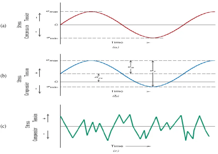
Depending upon the maximum and minimum principle stresses, there are various stress cycles as shown in Fig 2.11.
Fig. 2.11 Stress Cycles (a) Completely Reversed loading, (b) Repeated loading, and (c) Random loading
(a). Completely reversed cycle: I n Completely r e v e r s e d s t r e s s c y c l e t h e m a g n i t u d e o f m a x i m u m s t r e s s (σmax) minimum stress (σmin) are same but the sense is opposite. (b). Repeated stresses cycle: In repeated stress the maximum and minimum stresses are not same neither in magnitude nor in direction.
(c). Irregular or random stress cycle: In this type of stress cycle the variation of stress does not follow a definite pattern as shown in fig. 2.11 (c).
Fluctuating stress cycles are made up of two components:
(a)
(b)
22
1. Mean or steady stress (σm ): σm =(σmax + σmin)2
2. Alternating stress (σa): σa =(σmax − σmin)2
2.4.3. S-N Curve
The fatigue data is represented by using S-N curve. S-N curve is a plot between the bending stress (S) and number of cycles to failure (N) in log scale. Typical S-N curves are shown in fig 2.12 (a) and (b) [16].
Fig 2.12 Typical Fatigue Curve for Ferrous and Non-Ferrous materials.
Most of the fatigue tests of materials have been made in completely reversed cyclic loading where the mean stress (σm) becomes zero and tests are performed in rotating beam test machine. In high cycle fatigue to determine the S-N curve the specimen is first loaded at a high stress, where failure is expected to occur in short number of cycles. Then the stress is decreased subsequently up to a stress where one or two specimens does not fail after the specified number of cycles, which is usually about 106 to 107 cycles.
23
this limiting stress is called fatigue limit or endurance limit. Most nonferrous metals, like copper, aluminium, and magnesium alloys have an S-N curve which slopes gradually downwards with increasing number of cycles. For these materials the S- N curve never becomes horizontal and hence does not have a true fatigue limit.
For the low cycle fatigue test (N<105cycles), tests are conducted with controlled cycles of elastic and plastic strain rather than controlled load or stress. The conventional fatigue problems can be divided into the following kinds according to the number of cycles of fatigue:
Super cyclic fatigue (over 107)
High cyclic fatigue (from 105 to 107)
Low cyclic fatigue (from 103 to 105).
2.4.4. Fatigue Mechanism
Ewing and Humfrey [17] in 1903, studied the fatigue behaviour of Swedish iron. They found that after exceeding proportional limit the metal was deformed by slipping on certain plains. Different theories were put forward and concluded that the fatigue cracking was associated with slip. Gough [18] in 1923 gave another explanation about the fatigue mechanism. He explained that the fatigue failure of the ductile materials are consequence of slip.
Around 1960, the electron microscope observation was a crucial development for fatigue investigations. The Fractographic i m a g e revealed striations marks with respect to every load cycle [19]. Crack formation in fatigue can be studied by interrupting the test and removing the deformed surface by electro-polishing. After polishing several slip bands will be found which are more persistent than the others and they will remain visible while others have been polished away. These slip bands are observed only after 5 percent of the total life of specimen [20]. The persistent slip bands becomes wide cracks when a small tensile strain is
24
applied.
Initially fatigue cracks propagate along slip planes and later they propagate in a direction normal to the maximum tensile stress. The Fatigue crack propagation is ordinarily trans-granular.
An important structural feature appears in the fatigue deformation and that is the formation of ridges and grooves called slip band intrusions and slip band extrusions as shown in fig.2.13 [21].
A careful metallographic study on taper sections thorough the surface of the specimen has shown that the fatigue cracks initiate at intrusions and extrusions [22].
25
Chapter 3
26
Experimental Techniques
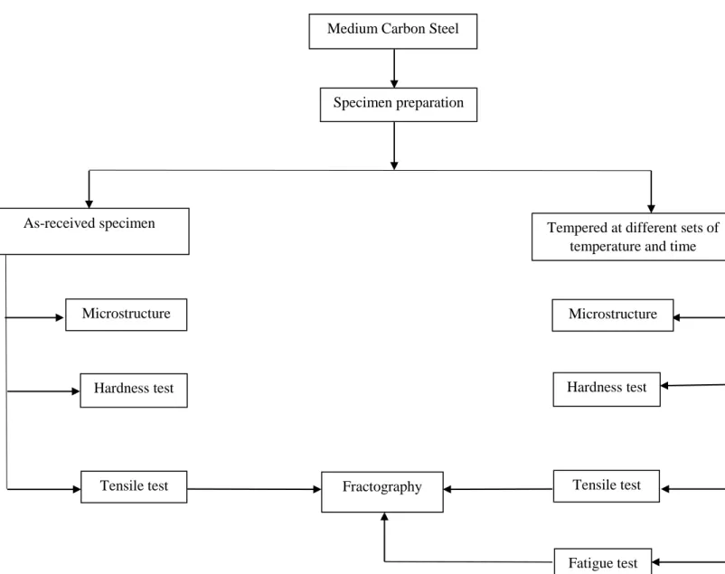
Fig 3.1 shows the experiments involved in this research work. The tests have been done in two groups, in first group the as received specimen is prepared for the different tests according to the required dimensions, and in the second group the specimens are quenched and tempered at different set of conditions and the test have been performed.
Fig 3.1: Experimental layout
Medium Carbon Steel
Specimen preparation
As-received specimen Tempered at different sets of
temperature and time
Microstructure Hardness test Tensile test Microstructure Hardness test Tensile test Fatigue test Fractography
27
The experimental techniques associated with the work are listed below:
1. Specimen preparation
2. Heat treatment (Quenching and tempering) 3. Microstructural analysis
4. Hardness test 5. Tensile test
6. Fatigue life estimation 7. Fractography.
3.1. Specimen preparation
The composition of the as received Medium carbon steel is given in the table 3.1. The microstructure of the Medium carbon steel contains ferrite and pearlite. Medium carbon steel has high hardness and strength with moderate ductility and significant amount of toughness.
Table 3.1: Composition of specimen ( % by weight)
C 0.524 % Mn 0.6903 % P 0.014 % S 0.02 % Ni 0.015 % Si 0.215 % Cr 0.211 % Mo 0.002 % V 0.032 % Cu 0.009 % Fe Balance
28
To carry out the experiments, the first job is to prepare the specimen as per the dimensions and design required. Fig 3.2 shows the design and dimensional specification for fatigue test. The specimen has a round cross section, the length of the specimen is 157 mm. and diameter at neck is 10 mm.
Fig 3.2: Specimen specification for fatigue and tensile test.
The specimens have been designed as per the R.R. Moore Rotating beam testing machine. Prior to the fabrication (machining) the heat treatments were done, keeping in mind that the heat treatment can result in some dimensional changes and scale formation.
For hardness test and microscopic investigations small pieces from rod were cut and polished.
3.2. Heat treatment (quenching and tempering)
Heat treatment is a process of subsequent heating and cooling to get different combinations of mechanical and physical properties. Quenching and tempering is most common and crucial heat treatment technique.
29
In this work tempering heat treatment has been done at three different temperatures 2000C, 4000C and 6000C for different durations of 60 min., 90 min., and 120 min. The austenitizing temperature was selected from Iron carbon diagram. Steps followed in the heat treatment are as follows:
Quenching
1. Specimens were first heated to 8500C, which is the austenitizing temperature for given composition.
2. At the temperature of 8500C the specimens were held for one hour, this is called soaking and this was done to obtain homogeneous austenite.
3. The specimens were then rapidly cooled or quenched in water bath, maintained at room temperature.
Tempering
Tempering was done at three different temperatures 2000C, 4000C, and 6000C.
1. Some specimens were heated at 2000C for 60 min., some for 90 min., and remaining for 120 min.
2. Same procedure was followed at 4000C and 6000C. 3. Heated specimens were then air cooled.
To prevent oxidation the specimens were placed in a charcoal container inside the furnace.
3.3. Investigation of Mechanical properties
The study of mechanical properties is the basic objective of this work. It is essential to compare the mechanical properties of differently tempered medium carbon steel specimens. Hardness test and tensile tests have been carried out to know the properties variation with respect to tempering time and temperature.
30
3.3.1 Hardness test
The hardness of as-received specimens as well as tempered specimens were measured in Vickers micro hardness testing machine (LM248at), as shown in fig. 3.3.
Fig. 3.3. Vickers microhardness testing machine
Procedure-
1. The specimen was placed in the machine
2. Dwell time was 10 sec.
3. 2 kg load was applied
4. The hardness values in HV were noted down.
3.3.2 Tensile test
To determine various tensile properties such as percentage elongation, yield stress, ultimate tensile stress. The as-received as well as differently tempered specimens were tested in Instron 1195.
31
Procedure-
1. The gauge length was calculated and the cross sectional area of the specimen was measured by an electronic slide caliper.
2. The distance between jaws was fixed to gauge length. 3. Specimen was fixed to the gripper
4. Specimen was loaded till failure
5. Engineering stress vs. strain curves were plotted with the help of load vs. displacement diagrams and the values of the yield stress, percent elongation, and ultimate stress were calculated by using following formulae :
% of Elongation =Change in gauge length
Original gauge length × 100
Yield strength = Load at 0.2% offset yield
Initial cross sectional area× 100
Ultimate Tensile Strength = Maximum load
Initial cross sectional area× 100
% Reduction of area =Change in gauge diameter
32
3.4. Microstructural analysis and Fractographical studies
The microstructures of as-received specimens and tempered specimens were studied in optical microscope. For that the specimens with 12mm. diameter and 10 mm. length were polished and etched by 2% Nital solution and then studied by optical microscope. Fig. 3.4 shows an optical microscope.
Fig. 3.4 Optical microscope.
The fractographs of the fractured specimens after tensile and fatigue tests were taken by
Scanning electron microscope, shown in
fig. 3.5.
33
3.5. Fatigue test
Fatigue life estimation is the main objective of this research work. R.R. Moore rotating beam testing machine is used to estimate the fatigue life. The schematic diagram of Rotating beam testing machine is shown in fig. 3.6.
Fig. 3.6 R.R. Moore rotating beam testing machine.
Procedure-
The specimen is clamped between two bearings and rotated by a motor about its longitudinal axis. A constant load is applied with the help of load pan. This results in application of a constant load with pure bending. The completely reversed stress pattern is achieved when specimen is rotated by spindles. In fig. 3.7 a completely reversed stress pattern with stress ratio R= -1 and zero mean stress is shown. In the present work specimens were loaded in the machine at a frequency of 100HZ.
34
Fig. 3.7. Completely reversed stress pattern
Working-
The symmetrically loaded specimen is rotated in the R.R. Moore testing machine. After half revolution the stresses originally below and above the neutral axis interchange their senses. At first the upper fibres are subjected to compression and lower fibres are subjected to tension. The formula of bending is applied to correlate the load and bending stress:
𝑴
𝑰
=
𝛔
𝐘
Where, M = Bending moment N-m I = Moment of inertia m4 σ = Bending stress (pa)Y = Distance from neutral axis.
35
Chapter 4
36
Results and Discussions
4.1 Introduction
The microstructure, mechanical properties, and fatigue life of medium carbon steel have been investigated in this research work. Mechanical properties such as hardness, tensile strength, and percentage elongation of as-received and differently tempered specimens have been measured and compared. The mechanical properties have been correlated with the microstructure.
The Fatigue life of differently tempered specimen have been studied and endurance limit has been calculated. The S-N curves are plotted for each set of Tempering temperature and time. Attempts have been made to correlate the endurance limit with the strength of the medium carbon steel specimens.
4.2 Microstructural analysis
Microstructure of as-received medium carbon steel
Microstructural analysis is essential because the mechanical properties are greatly influenced by the microstructure of the material. The microstructure of as-received medium carbon steel specimen has been studied in optical microscope. The optical micrograph is shown in fig. 4.1. The microstructure of medium carbon steel consists of ferrite (shown in light areas) and pearlite (shown in dark areas).
37
Fig. 4.1 Optical micrograph of as-received specimen (medium carbon steel) in 200X
Microstructure of tempered medium carbon steel
The microstructure of medium carbon steel after tempering has been studied on optical microscope. Fig 4.2, fig. 4.3, and fig. 4.4 show the microstructure of medium carbon steel tempered at 2000C, 4000C, and 6000C respectively.
Fig. 4.2 Optical micrograph of medium carbon steel tempered at 2000C, 200X
In the low temperature tempering i.e. at 2000C the tetragonality of martensite decreases and precipitation of epsilon- carbide occurs [6]. The resulting structure is called tempered martensitic structure.
38
Fig. 4.3 Optical micrograph of medium carbon steel tempered at 4000C, 200X
Fig. 4.4 Optical micrograph of medium carbon steel tempered at 6000C, 200X
In the intermediate temperature tempering at 4000C decomposition of retained austenite occurs and tetragonality of martensite is completely lost, and cementite rods are formed.
The high temperature tempering at 6000C results in coarsening and spheroidisation of cementite. Due to spheroidisation considerable amount of softness is induced in the material [24].
39
4.3 Mechanical properties
The study of mechanical properties comprises of hardness test and tensile test of as-received and tempered specimens. The comparison of properties between as-received and tempered specimens as well as between differently tempered specimens will be discussed later.
4.3.1 Hardness test
The hardness tests have been done under the microhardness testing machine, the test procedure has been already described in section 3.3.1. The results of hardness test has been given in table 4.1.
Table 4.1 Results of Hardness test
Specimen Tempering duration Vickers hardness (HV)
As-received nil 350 Tempered at 2000C 60 min. 778 90 min. 740 120 min. 718 Tempered at 4000C 60 min. 665 90 min. 585 120 min. 560 Tempered at 6000C 60 min. 512 90 min. 490 120 min. 478
40
Fig 4.5 shows the comparison of hardness between as-received and tempered medium carbon steel. It can be seen that the quenched and tempered specimens have higher hardness than the as-received medium carbon steel specimens. It can be seen that, as the tempering temperature is increased some amount of softness is induced in the material.
Fig. 4.5 Comparison of hardness between as-received and tempered conditions
The hardness values for different tempering conditions are compared and shown in Fig. 4.6. The variation of hardness with respect to tempering time and tempering duration is shown in the graph. 0 100 200 300 400 500 600 700 800 900
As-recieved Tempered at 200°C Tempered at 400°C Tempered at 600°C
Vick er s H a rdnes s (H V)
Comparison of Hardness
41
Fig. 4.6 Comparison of hardness between different tempering conditions.
It can be seen that the tempering temperature as well as the tempering duration can alter the hardness of the material. For tempering at any of the three temperatures the hardness is maximum for the specimens tempered for 60 min. and minimum for 120 min. this is due to the fact that the phase which is tempered for lower time duration has a finer structure [25-26].
The decrease in hardness with increase in tempering temperature is due to the formation of low tetragonality tempered martensitic structure which was martensitic after quenching. Martensite has a BCT structure and is a very hard phase in which carbon is occupied in the tetrahedral voids. The transformation of martensite is diffusion less and called athermal transformation. On tempering of martensite carbon diffuses from the tetrahedral voids which reduces the tetragonality of the martensite, due to this the hardness of tempered martensite becomes less than the original martensite [27].
0 100 200 300 400 500 600 700 800 900
Tempered at 200°C Tempered at 400°C Tempered at 600°C
Vick ers H a rdn es s (H V)
Comparison of Hardness for Tempering
60 min. 90 min. 120 min.
42
4.3.2 Tensile test results
The tensile test and its procedure has been discussed in section 3.3.2. Tensile test is essential to study the static loading behaviour as well as strength and ductility of the material. The Engineering stress vs. strain curves for different tempering conditions are shown in Fig. 4.7 to 4.15. 0.00 0.02 0.04 0.06 0.08 0.10 0 200 400 600 800 1000 En in e e ri n g st re ss (Mp a ) Engineering strain Tempering at 2000C, 60 min.
Fig. 4.7 Engineering stress vs. strain curve, Tempering at 2000C, 60 min.
0.00 0.02 0.04 0.06 0.08 0.10 0 200 400 600 800 1000 En g in e e ri n g st re ss (Mp a ) Engineering strain Tempering at 2000C, 90 min.
43 0.00 0.02 0.04 0.06 0.08 0.10 0.12 0.14 0.16 0 200 400 600 800 1000 En g in e e ri n g st re ss (Mp a ) Engineering strain Tempering at 2000C, 120 min.
Fig. 4.9 Engineering stress vs. strain curve, Tempering at 2000C, 120 min.
Fig. 4.7, fig 4.8, and fig 4.9 show the engineering stress vs. strain curve for tempering at 2000C with tempering duration of 60 min., 90 min., and 120 min. respectively. The yield strength and ultimate tensile strength of the specimens tempered at 2000C, 60 min. are maximum. The yield strength is 830.21 Mpa and U.T.S. is 989.38 Mpa which is more than Y.S. and U.T.S. for 90 min. and 120 min. with a minimum value for 120 min.
Another important property is the ductility. The percentage elongation is maximum for the specimens tempered for a duration of 120 min. and minimum for the 90 min. For tempering at 2000C, 120 min. the percentage elongation is found to be 15 while it is 10 for tempering duration of 90 min. and 9 for 60 min. tempering duration. So it can be seen that with increase in tempering duration the strength is decreased and the ductility is increased.
44 0.00 0.05 0.10 0.15 0.20 0 200 400 600 800 1000 En g in e e ri n g st re ss (Mp a ) Engineering stress Tempering at 4000C, 60 min.
Fig. 4.10. Engineering stress vs. strain curve, Tempering at 4000C, 60 min.
0.00 0.05 0.10 0.15 0.20 0 200 400 600 800 1000 En g in e e ri n g st re ss (Mp a ) Engineering strain Tempering at 4000C, 90 min.
45 0.00 0.05 0.10 0.15 0.20 0 200 400 600 800 En g in e e ri n g st re ss (Mp a ) Engineeing strain Tempering at 4000C, 120 min.
Fig. 4.12 Engineering stress vs. strain curve, Tempering at 4000C, 120 min.
The Engineering stress vs. strain curves for medium carbon steel tempered at 4000 for 60 min., 90 min., and 120 min are shown in fig. 4.10, fig. 4.11, and fig. 4.12 respectively. Here we can see that the medium carbon steel tempered at 4000C has more ductility than the specimens tempered at 2000C. The maximum percentage elongation is 19.5 for tempering at 4000C, 120 min., this indicates significant amount of softness has been induced in the material after tempering at 4000C. For tempering at 4000C, 60 min. the percentage elongation is 18.5 which is lowest for this temperature but still higher than the maximum percentage elongation at 2000C range. The Y.S. and U.T.S has been decreased due to tempering at 4000C as compared to tempering at 2000C. At 2000C, 60 min. the Y.S. was 830.21 Mpa and the U.T.S. was 989.38 Mpa, which decreased to 650 Mpa and 940 Mpa respectively, when tempered at 4000C, 60 min. Even at 4000C the best results as per the strength are for 60 min. duration. The tempering at 4000C for 120 min. leads to loss of strength but increase in ductility.
46 0.00 0.05 0.10 0.15 0.20 0 200 400 600 800 En g in e e ri n g st re ss (Mp a ) Engineering stress Tempering at 6000C, 60 min.
Fig. 4.13 Engineering stress vs. strain curve, Tempering at 6000C, 60 min.
0.00 0.05 0.10 0.15 0.20 0.25 0 100 200 300 400 500 600 700 En g in e e ri n g st re ss (Mp a ) Engineering strain Tempering at 6000C, 90 min.
47 0.00 0.05 0.10 0.15 0.20 0.25 0 100 200 300 400 500 600 700 En g in e e ri n g st re ss (Mp a ) Engineering strain Tempering at 6000C, 60 min.
Fig. 4.15 Engineering stress vs. strain curve, Tempering at 6000C, 120 min.
Tempering at 6000C follows the same trend as 2000C and 4000C as far as the tensile properties are concerned. The ductility is highest for the tempering at 6000C for any duration. This may be due to the formation of spheroidal cementite. The maximum percent elongation is 22 when tempered at 6000C, 120 min. For tempering at 6000C the minimum percentage elongation is 20.5, which is higher than percentage elongation for tempering at both the 2000C and 4000C range. As the material tempered at 6000C is very soft, it lacks in strength. The maximum Y.S. for 6000C tempering is 470 Mpa and maximum U.T.S. is 794.12 Mpa when tempered for a duration of 60 min., which is less than the Y.S. and U.T.S. of medium carbon steel tempered at 2000C and 4000C range.
The values of yield strength, Ultimate tensile strength, and percentage elongation were taken from the engineering stress vs. strain curves. These values are tabulated with respect to different tempering conditions in table 4.2.
48
Table 4.2 Tensile properties of as-received and differently tempered medium carbon steel
Specification of Specimen Tempering duration Yield Stress (YS) in MPa Ultimate Tensile Stress in MPa % of Elongation Maximum Load in KN As-received --- 410.61 597.78 19.5 46.94 Tempered at 2000C 60 min. 830.21 989.38 9 77.70 90 min. 818 974.31 10 76.52 120 min. 739 959.78 15 75.38 Tempered at 4000C 60 min. 650 940 18.5 73.82 90 min. 527 907.71 19 71.29 120 min. 489.28 812.14 19.5 63.78 Tempered at 6000C 60 min. 470 794.12 20.5 62.37 90 min. 457 720 21 56.54 120 min. 443 698.73 22 54.87
49
Fig. 4.16 Comparison of Yield stress between as-received and tempered conditions.
Fig. 4.17. Comparison of Yield stress between differently tempered conditions.
0 100 200 300 400 500 600 700 800 900
As-recieved Tempered at 200°C Tempered at 400°C Tempered at 600°C
Yield st re ss ( M pa )
Comparison of Yield stress
0 100 200 300 400 500 600 700 800 900
Tempered at 200°C Tempered at 400°C Tempered at 600°C
Yield st re ss ( M pa )
Comparison of Yield stress for tempering
60 min. 90 min. 120 min.
50
Fig. 4.18 Comparison of Ultimate tensile stress between as-received and tempered conditions
Fig. 4.19. Comparison of Ultimate tensile stress between differently tempered conditions.
0 200 400 600 800 1000 1200
As-recieved Tempering at 200°C Tempering at 400°C Tempering at 600°C
Ult im a te tens ile st re ss ( M pa )
Comparison of Ultimate tensile stress
0 200 400 600 800 1000 1200
Tempered at 200°C Tempered at 400°C Tempered at 600°C
Ult im a te tens ile st re ss ( M pa )
Comparison of Ultimate tensile stress
for tempering
60 min. 90 min. 120 min.
51
Fig. 4.20 Comparison of % Elongation between as-received and tempered conditions.
Fig. 4.21. Comparison of % Elongation between differently tempered conditions.
0 5 10 15 20 25
As-recieved Tempered at 200°C Tempered at 400°C Tempered at 600°C
% E lo ng a tio n
Comparision of % elongation
0 5 10 15 20 25Tempered at 200°C Tempered at 400°C Tempered at 600°C
% E lo ng a tio n
Comparison of % elongation for
tempering
60 min. 90 min. 120 min.
52
From the results of tensile tests it can be seen that there exists a structure-property relationship. Some observations have been made as follows:
1. Quenching followed by tempering improved the mechanical properties of the medium carbon steel.
2. The microstructural analysis indicated that the medium carbon steel specimens tempered at low temperatures have tempered martensitic structure [28-30]
3. Low temperature tempering gave the best results, the microstructure of specimens tempered at low temperature(2000C) are tempered martensite, which is comparatively harder than the structures obtained during intermediate(4000C) and high temperature(6000C) tempering.
4. The ductility is maximum for the high temperature (6000C) tempering while hardness and tensile strength are maximum for low temperature (2000C) tempering.
5. With an increase in tempering duration at same tempering temperature, the ductility is increased with significant decrease in hardness and tensile strength.
53
4.4 Fractographical studies after tensile test.
Fig 4.22 Fractograph after tensile test, 2000C Tempering, (a) 2000X, (b) 3000X
Fig 4.23 Fractograph after tensile test, 4000C Tempering, (a) 2000X, (b) 3000X
(a) (b)
54
Fig 4.24 Fractograph after tensile test, 6000C Tempering, (a) 2000X, (b) 3000X
The fractographs of fractured surfaces after tensile test are shown in Fig. 4.22, 4.23, and 4.24. The medium carbon steel specimens tempered at 2000C show a mixed pattern of fracture, may be due to presence of comparatively hard and brittle phase tempered martensite. The medium carbon steel specimens tempered at comparatively high temperatures show mainly a ductile fracture. In Fig. 4.24 tensile fractograph of medium carbon steel tempered at 6000C is shown which indicates a ductile fracture with dimpled structure [11]. It shows that considerable amount of ductility is induced in the material.
4.5 Fatigue life estimation
The procedure and working principle of R.R. moore rotating beam testing machine is already discussed in section 3.5. S-N curves of differently tempered specimens have been plotted and shown in fig.4.25 to fig.4.33.
55
Fig 4.25 S-N Curve, Tempered at 200 0C, 60 min.
Fig 4.26 S-N Curve, Tempered at 200 0C, 90 min.
105 106 107 600 650 700 750 800 850 Tempering at 2000C, 60 min. Al te rn a tin g st re ss (Mp a )
No. of cycles to failure, (N)
105 106 107 550 600 650 700 750 800 850 Tempering at 2000C, 90 min. Al te rn a tin g st re ss (Mp a )
56 105 106 107 400 450 500 550 600 650 700 750 800 850 Tempering at 2000 C, 120 min. Al te rn a tin g st re ss (Mp a )
No. of cycles to failure, (N)
Fig 4.27 S-N Curve, Tempered at 200 0C, 120 min.
105 106 107 500 520 540 560 580 600 620 640 660 Tempering at 4000C, 60 min. Al te rn a tin g st re ss (Mp a )
No. of cycles to failure, (N)
57 105 106 107 440 460 480 500 520 540 Tempering at 4000 C, 90 min. Al te rn a tin g st re ss (Mp a )
No. of cycles to failure, (N)
Fig 4.29 S-N Curve, Tempered at 400 0C, 90 min.
105 106 107 380 400 420 440 460 480 500 Tempered at 4000C, 120 min. Al te rn a tin g st re ss (Mp a )
No. of cycles to failure, (N)
58 105 106 360 380 400 420 440 460 480 Tempring at 6000 C, 60 min. Al te rn a tin g st re ss (Mp a )
No. of cycles to failure, (N)
Fig 4.31 S-N Curve, Tempered at 600 0C, 60 min.
105 106 107 360 380 400 420 440 460 Tempering at 6000 C, 90 min. Al te rn a tin g st re ss (Mp a )
No. of cycles to failure, (N)
59 106 107 340 360 380 400 420 440 460 Tempering at 6000 C, 120 min. Al te rn a tin g st re ss (Mp a )
No. of cycles to failure, (N)
Fig 4.33 S-N Curve, Tempered at 600 0C, 120 min.
S-N curve is very useful in showing the variation of stresses with respect to number of cycles to failure. In fig. 4.34 comparison of fatigue limits of medium carbon steel tempered at different sets of temperature and time is shown.
Fig. 4.34 Comparison of fatigue limit between differently tempered conditions
0 100 200 300 400 500 600 700
Tempered at 200°C Tempered at 400°C Tempered at 600°C
Fatig u e lim it (Mp a)
Comparison of fatigue limit for tempering
60 min. 90 min. 120 min.
60
Some comparisons of S-N curves are shown in Fig. 4.35 (a), (b), and (c),
105 106 107 450 500 550 600 650 700 750 800 850 Tempering at 2000 C, 60 min. Tempering at 2000 C, 90 min. Tempering at 2000 C, 120 min. Al te rn a tin g st re ss (Mp a )
No. of cycles to failure, (N)
Fig. 4.35 (a) S-N curves for tempering at 2000C, for different time durations.
105 106 107 380 400 420 440 460 480 500 520 540 560 580 600 620 640 660 Tempering at 4000 C, 60 min. Tempering at 4000 C, 90 min. Tempering at 4000 C, 120 min. Al te rn a tin g st re ss (Mp a )
No. of cycles to failure, (N)
61 105 106 107 340 360 380 400 420 440 460 480 Tempering at 6000 C, 60 min. Tempering at 6000 C, 90 min. Tempering at 6000 C, 120 min. Al te rn a tin g st re ss (Mp a )
No. of cycles to failure, (N)
Fig. 4.35 (c) S-N curves for tempering at 4000C, for different time durations.
From the S-N curves it is clear that the medium carbon steel specimens tempered at 2000C have the maximum endurance limit, when compared to specimens tempered at 4000C and 6000C. For any temperature the maximum endurance limit is reached when the specimen is tempered for 60 min. which shows that the variation of endurance limit follows the same trend as yield stress.
The highest fatigue limit for tempering at 2000C is 625 Mpa, for tempering at 4000C is 520 Mpa, and for tempering at 6000C is 375 Mpa. The low temperature tempering shows the best result in terms of fatigue limit. Also fatigue limit is higher for specimens with high yield stress.
From fig. 4.34 it can be seen that, while keeping the tempering temperature constant the endurance limit varies for different tempering durations. If variatio
![Fig. 2.3: SEM micrographs of the microstructure of 0.05%wt C steel ferrite(dark) and pearlite(light) [4]](https://thumb-us.123doks.com/thumbv2/123dok_us/74013.2508438/20.894.221.672.104.386/fig-sem-micrographs-microstructure-steel-ferrite-pearlite-light.webp)
![Fig. 2.4 Optical micrograph of 0.4% wt. Carbon steel in 1100X [5].](https://thumb-us.123doks.com/thumbv2/123dok_us/74013.2508438/21.894.278.618.512.813/fig-optical-micrograph-wt-carbon-steel-x.webp)