AUTOMATED ELECTRICAL INSTALLATION DESIGN
USING JAVA SCRIPT PROGRAM
M. S. Othman
Faculty of Electrical Engineering Universiti Teknologi MARA
Shah Alam, 40450 MALAYSIA [email protected]
ABSTRACT
This paper describes a case study how electrical installation is design in a building that is based on IEE regulation and Jabatan Kerja Raya (JKR) standard specification. The study demonstrates the design of lighting, socket outlet, air condition, system protection, cable sizing and generator sizing. The load estimation of maximum demand and total connected load was calculated. From load estimation main switch board (MSB) Sub Switch Board (SSB), Essential Switch Board (EMSB) and Distribution Board (DB) which is the back bone of the electrical installation are designed. A software using JAVA script program is also developed for all calculation used.
Keywords: MCB (Main Circuit Breaker), RCCB (Residual Current Circuit Breaker), MCCB (Moulded Case Circuit Breakers), MSB (Main Switch Board), LDL (Lighting Design Lumen). TPN (Three pole Neutral), SPN (Single Pole Neutral)
1.0 INTRODUCTION
Electrical installation covers almost every aspect of our national life from domestic, recreational, medical, commercial and industrial.[1] Electrical installation is an essential requirement for conveying, safely and efficiently, electrical energy from the paint of supply to the current using devices such as lamp, heaters and motors. According to Michael Neidle Electrical installation must confirm to the safety rule: "All apparatus and conductors shall be sufficient in sizes and power for the work they are called upon to do, and so constructed, installed, protected, worked and maintained as to prevent danger as far is reasonably practicable ". [2]. The reason to have safety electrical installation is to reduce the hazards posed by unsafe domestic electrical installations and thereby help to reduce injuries from electrical shocks, burns, overheating or arcing. [3]
This project presents the development of electrical design and installation using Java Script program at the “Multipurpose Hall ". Electrical installation and 1oad estimation was calculated. The sizes of MSB, EMSB, SSB and DB were also determined. The voltage drop and protection system was also included in the study. The design drawing was implemented using AutoCAD 2008 version. All standard and specification are referred to IEE regulation, JKR standard, British Standard (BS) and Illumination Engineering UK Code Practice [4].
2.0 SCOPE OF WORK
This project focus on developed and designs the electrical installation design for multipurpose hall using Java Script program. The load is estimated by calculation of maximum demand (MD) and total connected load (TCL).The Protection system from short circuit, overload, earth fault and earth leakage and lightning protection was determined after inserting electrical devices. Final electrical drawing was draw and is goes through final checking to must be not ‘overdesign’.
3.0 DESIGN METHODOLOGY
This project focus on developing an electrical installation designs for multipurpose hall. In general, the scope of work was focus on new software tool developed, which is Automated Electrical installation Design Using Java Script Program. The Detail scopes are:
1. Drawing and design a schematic diagram and equipment using Auto CAD 2008. The drawing includes the schematic diagram, switch socket outlet and lighting design. AutoCAD
software make the drawing task is much easier and nicer.
2. Develop a program to calculate for all design tasks likes lighting design, MCCB design and voltage drop design using Java Script program. 3. Develop a website for all electrical
design using Microsoft Notepad.
Figure 1 shows the flowchart for the development of the user interface to locate the source of the installation relative to monitoring point. In the figure, four steps are to be taken before the results are displayed. The first step is to open program for choosing the lighting, MSB and voltage drop design. After that zero crossing is performed on these data source to enable the calculation. The third step is to calculate the indices for each particular. The fourth step is to perform the analysis as whether of data applicable for design the electrical installation and will later be displayed on the screen.
The procedure to locate the electrical installation design can be explained as follows:
Figure 1.0 Flowchart of the automated software.
3.1 TOTAL CONNECTED LOAD (TCL) DAN MAXIMUM DEMAND (MD
)
Total connected load is a total electrical power needed when all the lamps and socket outlet used in bulding. Maximum load is maximum power needed to the installation (buildings, complexs etc). This maximum power actually not to be same and rarely same to the power needed by total connected load. The differences or ratio between the maximum load to the total connected load known as diversity factor. Maximum demand can be calculated by this formula :-
Maximum demand (MD) = total connected load(TCL) x diversity factor (DF)
or
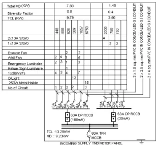
M.D.= T.C.L. x D.F. ---(1) In finding the maximum demand for every new building, every factor should be calculated pricisely so that the system that will be design is not overdesign or under-designed. Figure 4.1 below shows the example for calculating the TCL and MD.
Figure 1.1 Simple Calculations in Drawing Figure 1.1 is show the important drawing and used as a main reference in design stage for electrical installation in multipurpose hall by referring to the this drawing it provided all the important information for the project such as voltage supply (high voltage or low voltage), total connected load (TCL) in a project, distribution board (DB), Sub Switch Board (SSB), Main Switch Board (MSB).
START
Select the menu
Insert the data
Calculate the indices for each particular
Analysis the installation design
Display result
4.0 SOFTWARE RESULT AND DISCUSSIONS
The results of the automated electrical installation design are presented for each program menu.
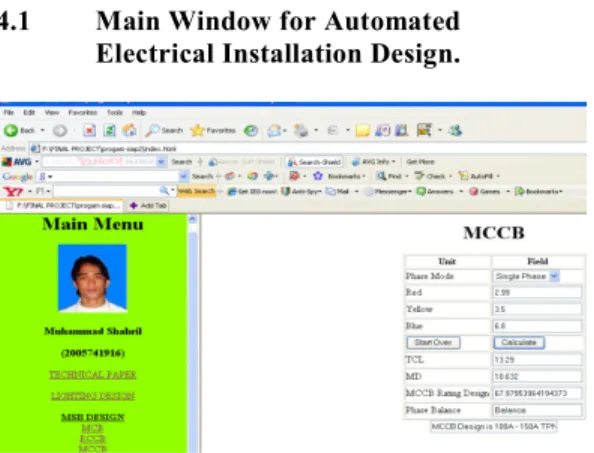
4.1 Main Window for Automated Electrical Installation Design.
Figure 2 Interface using Java Script Program. Figure 2 show the electrical design website that provides program menu and table for reference. A user can select a program by clicking any programs under program menu.
5.0 LIGHTING DESIGN
The purpose of light design is to get a suitable lux level for specific places. There are a three specification to be determined, Room index, installed flux and no of light used in those places. [2]
5.1 LUMENS METHOD CALCULATION The purpose of lumens calculation is to determine the total lights needed in a correct quantity according to the specification provided. Before begin the calculation, several aspects must be identified such as:-
• Room length (L)
• Room width (W)
• Mounting Height (Hm)
• Types of room
• Ceiling and wall color
After the above matter is considered, the type of light can only be determined such as fluorescent lights, decorative lights or domestic and industrial lights. However, the most important aspect is the distribution of lights of the luminaries.
Table 1 a) The standard Lumen level
5.1.1 Example of Calculation
Assuming that a designer wants to design the interior lighting system for an office that has length of 24.4 meter, width of 14.6 meter and the ceiling height is 7.3 meter. The designer wanted to use a standard 250W Metal halide luminaire that needs to be fitted into the ceiling (pyramid recessed shallow fitting with diffusing sides, optically design downward reflecting surface). The designer knows that the JKR standard illuminance for general office is 250 lux and the wall and ceiling color is white.
Calculation of the room index; R.I = Length x Width --- (1)
Height (Length + Width) R.I = 24.4 x 14.6 7.3 (24.4 + 14.6)
= 1.25
To obtain the Utilization Factor (Uf), the reflection factor table is use. Because of the color of wall and ceiling is white, thus the reflection factor of 70% (ceiling) and 30% (walls) must be used;
From the table Uf = 0.36.
With maintenance factor 0.8, the number of the lamp can be calculated by using Lumen Method. Installer flux = Illuminance x Area --- (2) Uf x Mf
= 250 x 24.4x 14.6 0.36 x 0.8
= 309236 lumens
*The lighting design lumen output of the lamp depends on its color but for particular type might be 20000 lumens.
Number of lamps = Installer flux --- (3) Lighting design lumen
LIGHTING TYPE Lumen
Metal Halide 250W 20000
Fluorescent 1 x 36W 3050
= 309236 20000
= 15 lamps
Table 1(b): Room Index and Room Utility Table (Downward Light Output Ratio 50%)
The table 1 b) show the roam index is 1.25, utilization factor 0.36 and no of light point are 15 lamps.
Figure 3 Lighting Design
Figure 3 show room index and no of light result. With the room length, room width and room height respectively 24.4 and 14.6, the room index is 1.25. The value is all in meter (m) by referring table 1 (b). Using combination of ceiling 70 %, wall 50 % and the Utilization Factor Uf = 0.36. Therefore the accurate Room Index RI is 1.25. After that the lux is 250 with using LDL =20000 by referring table 1 a). Finally the no of light point is equal to 15 lamps.
5.2 Result and Discussion
Table 1 c) shows the summary of lighting design
From result above, a number of lights are influences by a few factors as below:
i. The bigger the room area the more number of lights use.
ii. The bigger the lux the more number of lights use.
iii. The bigger the room utility the more number of lights use.
iv. The bigger the LDL the less no of light
5.3 MCCB, RCCB and MCB design in MSB
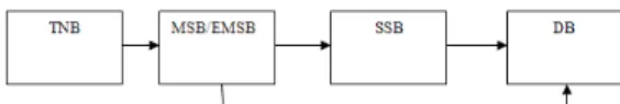
From TNB supply to Main Switch Board (MSB) power will distributed to Sub Switch Board (SSB) and Distribution Board (DB). In MCCB design a data need is power for each phase. The program also calculated the total connected load and maximum demand.
Figure 4.1: Power distribution from service line to building. Reflection Factor % ceiling 70 wall 50 30 10 Room Index 0.60 0.24 021 0.19 0.80 0.30 0.27 0.24 1.00 0.33 0.30 0.27 1.25 0.36 0.33 0.30 1.50 0.39 0.36 0.33
Area Room Installation Number
Index Flux (If) of Lamp
Existing Hall 1.25 309236 15 Entrance Porch 1.17 3327 11 Existing 0.5 7130 2 Store/ Audio Corridor 0.19 10161 3 Existing Toilet 0.5 9507 3
Figure 4.3 a) MCB Design
Figure 4.3 a) show a suitable MCB for this ESSB is 60A TPN. The load is balance between the phases with TCL 6.8kW. After that, the current sensitivity 100A must be using to Residual Current circuit Breaker (RCCB) design. The data need from figure above is a Load Power and MCB Rating.
Figure 4.3 b) RCCB Design
Figure 4.3 b) shows a suitable RCCB design is 40A SPN. The load power with TCL is 2.99kW and maximum demand MD is 2.39kW. The data need from figure above is a TCL and RCCB Rating.
Figure 4.3 c) MCCB Design
Figure 4.2 c) show a suitable for this MCCB design is 60A TPN. The load is balance between the phases with TCL is 13.3kW and MD is 9.25kW. After that, the cables sizes must be determine using voltage drop design. The data need from figure above is a TCL and MCCB Rating.
Table 4.3: TCL and MD Calculation
TYPE POWER ( WATT ) QUANTIT Y T.C.L ( KW ) DIVERSITY FACTOR MAXIMU M DEMAND ( KW) METAL HALIDE 250W 250 X 1.8 15 6.80 0.8 5.44 1 x 36W (F) 36x 1.8 18 1.17 0.8 0.94 KELUAR SIGN LUMINA IRE 8 x 1.8 1 0.02 0.8 0.01 EMERGE NCE LIGHT LUMINA IRE 8 x 1.8 9 0.13 0.8 0.1 WALL FAN 80 12 0.96 0.8 0.77 EXHAUS T FAN 80 4 0.32 0.8 0.26 1 x 13A S/S/O 250 6 1.50 0.4 0.6 2 x 13A S/S/O 500 4 2.00 0.4 0.8 DOWN LIGHT 18 x 1.8 12 0.39 0.8 0.31 Total TCL 13.3 Total MD 9.25
From result above the MCCB design use is TPN (Three Pole Neutral) and SPN (Single Pole Neutral). The maximum demand (MD) is 9.25kw at MSB and the total connected load (TCL) is 13.3kw.The result current design we can gat 60A. The load a suitable MCCB is using TPN. The bigger the power at load, the current design has a bigger in MCCB rating.
5.4 VOLTAGE DROP
There are voltage drop in the cable when the current flow because there is an internal resistance in every cable. The IEE Regulations require that the voltage drop Vd should not be so
excessive that equipment does not function safely. The voltage drop must be no more than 4% of the nominal or supply voltage. The standard permit a 4% voltage drop within an installation from the supply intake to the terminal of current using equipment or a socket outlet. At 230V, the voltage drop is 9.2V and 400V, the voltage drop is 16V. Care need to be taken in the selection of cable, particularly where equipment is voltage sensitive. [4]
5.4.1 Calculation of Design Voltage Drop Then define voltage drop Vd as single phase or three phase. Find milivolt/ampere/meter (mv) by using formula
Vd = mV x I x L --- (1) 1000
Ib<In<Iz
In = the nominal current or current setting of
the device protecting the circuit against over current.
Iz = the current carrying capacity of a cable for continuous service under the particular installation condition concerned.
Ib = The designed current of the circuit. For example current intended to be carried by the circuit in normal service.
Choose In SPN or TPN MCB as protection device. Iz = ூே
Using table 4D4A to find the cable size. Calculate the voltage drop.
Vd = ൈூൈ ଵ
5.4.2Voltage Drop Program
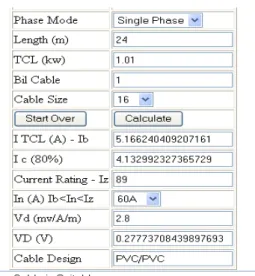
Figure 5.2 Voltage Drop Calculations
Figure 5.1 show the voltage drop must less than 4 % of the nominal supply terminal voltage (230V or 4 00V). Since it is 0.28V and less than 9.2V (4%) it is save to use the cable.
Table 3 Voltage drop Result
From result above, the main parts to determine for a cable sizes is a total power flow inside a cable and the length of a cable to be connected. The bigger power to flow inside a cable the bigger the cable sizes. Beside that, the bigger of cable length the higher the voltage drop.
6.0 CONCLUSION
This project demonstrates the electrical design process in educational building. The electrical design was first calculated manually using EXCELL. Then Java script programming was developed for all calculation to replace EXCELL. After that all program are combine in a website and calculation for the design will be faster and more accurate. The program also can be upgraded to be more informative. The website design is use to combine all program involve and table that need to be refer as stated in IEE and JKR specification. User just can explore using Internet connection without installing other software to excess the program because it use Microsoft Internet explorer to running the program. The program is also suitable to use for any building that using IEE and JKR Specification. The program also helps in drawing schematic diagram such as DB design. User can faster get result using this program, can prevent a careless mistake and it helps to solve electrical design in building for all calculation likes lighting, voltage drop and MCCB Rating.
7.0 FUTURE DEVELOPMENT
For future development, the JAVA script program can be upgrade to be come one main program. The website also can be upgraded by providing a data base system.
8.0 ACNOWLEDGEMENT
Firstly, I would like to express my gratitude to my project supervisor, Assoc. Prof. Noraliza Bt Hamzah for her guidance, advice, support, comment, and kindness given toward completing this project. I also likes to thanks to En Mohd Rudzuan Bin Ariffin (JPPK) En Fadli Bin Ishak (MYNIC) for their help to make this project success.
9.0 REFERENCES
[1] Brian Scaddan "IEE wiring regulation Explained And Illustrated" Heinemann Newnes.
[2] Michael Neidle " Electrical Installation and Regulations. The Macmillan Press LTD 1974.
[3] F. Porges " The Design of Electrical Services for Buildings. London New York E. & F. N. Third Edition 1989.
[4] Jabatan Kerja Raya (JKR)"Panduan Teknik " 2006.
[5] Requirement for Electrical Installations, IEE wiring regulations sixteenth Edition 1997. [6] Deitei Nieto "Internet & world Wide Web
Program How to program" Prentice Hall 2000. [7] A.J Coker and W Turner Revise by
B.Scaddan " Electrical Wiring Domestic" Newness 1992
[8] John E Traister " Industrial Electrical Wiring (Design, Installation, maintenances) Mc Graw Hill 1997.
[9] Peter Jay and John Hemsley "Electrical Services Building " Elsevier Publishing Company
[10] Scaddan, Brian,” The IEE Wiring Regulation, Explained and Illustrated”, Brian Scaddan 1989.