ELECTRICAL ENGINEERING
Design adaptive neuro-fuzzy speed controller
for an electro-mechanical system
B.A.A. Omar
*
, A.Y.M. Haikal, F.F.G. Areed
Computer and Systems Department, Faculty of Engineering, Mansoura University, Mansoura, Egypt Received 24 November 2010; revised 22 June 2011; accepted 9 July 2011
Available online 30 August 2011
KEYWORDS
Adaptive neuro-fuzzy infer-ence;
Chopper circuit; SEDM; Speed control
Abstract In this paper an adaptive neuro-fuzzy inference system (ANFIS) controller using error and derivative of error inputs is proposed for the speed control of a separately excited DC motor (SEDM) using chopper circuit. This paper investigates the design and simulation of an adaptive neuro-fuzzy inference system (ANFIS) controller for the speed of DC motor. The performance of the proposed system has been compared with conventional one, where the conventional PI con-troller (speed concon-troller) in the chopper-fed DC motor drive is replaced by the adaptive neuro-fuzzy controller to improve the dynamic behavior of the model. Computer Simulation is conducted to demonstrate the performance of the proposed controller and results show that the proposed design succeeded over the conventional PI controller where it make reduction of number of ripples and rise time. The entire system has been modeled using MATLAB 2009 toolbox.
Ó2011 Ain Shams University. Production and hosting by Elsevier B.V. All rights reserved.
1. Introduction
Direct current (DC) motors have been widely used in many industrial applications such as electric vehicles, steel rolling mills, electric cranes, and robotic manipulators due to precise,
wide, simple, and continuous control characteristics. So we studied this example of its importance and try to solve its problems in different ways. Traditionally armature control method was widely used for the speed control of low power DC motors. However the controllability, cheapness, higher efficiency, and higher current carrying capabilities of static power converters brought a major change in the performance of electrical drives. The desired torque-speed characteristics could be achieved by the use of conventional proportional integral-derivative (PID) controllers. Since PID controllers require exact mathematical model. The adaptive neuro-fuzzy inference system (ANFIS), developed in the early 1990s by Jang [1], combines the concepts of fuzzy logic and neural networks to form a hybrid intelligent system that enhances the ability to automatically learn and adapt hybrid systems have been used by researchers for modeling and predictions in various engineering systems. The basic idea behind these * Corresponding author.
E-mail address:basmaomar78@yahoo.co.uk(B.A.A. Omar). 2090-4479Ó2011 Ain Shams University. Production and hosting by Elsevier B.V. All rights reserved.
Peer review under responsibility of Ain Shams University. doi:10.1016/j.asej.2011.07.003
Production and hosting by Elsevier
Ain Shams University
Ain Shams Engineering Journal
www.elsevier.com/locate/asej www.sciencedirect.com
neuro-adaptive learning techniques is to provide a method for the fuzzy modeling procedure to learn information about a data.
Set, in order to automatically compute the membership function parameters that best allow the associated FIS to track the given input/output data. The membership function param-eters are tuned using a combination of least squares estimation and back-propagation algorithm. These parameters associated with the membership functions will change through the learn-ing process similar to that of a neural network. Their adjust-ment is facilitated by a gradient vector, which provides a measure of how well the FIS is modeling the input/output data for a given set of parameters. Once the gradient vector is obtained, any of several optimization routines could be applied in order to adjust the output so as to reduce error between the actual and desired outputs. This allows the fuzzy system to learn from the data it is modeling. The approach has the advantage over the pure fuzzy paradigm that the need for the human operator to tune the system by adjusting the bounds of the membership functions is removed. An open loop control system which can predict the dynamic behavior of systems involving mechanic and electronic modules has been successfully designed and implemented to control the speed of a DC motor[2]. The superior performance of artificial intel-ligence (AI) based controllers urged power system and power electronic engineers to replace conventional speed control circuit with intelligent speed controllers[3,4].
2. Modeling of DC motor
The DC motor is the obvious proving ground for advanced control algorithms in electric drives due to the stable and straight forward characteristics associated with it. It is also ide-ally suited for trajectory control applications. From a control systems point of view, the DC motor can be considered as SISO plant, there by eliminating the complications associated with a multi-input drive system[5].
2.1. Dynamics of a DC motor
Dynamics of a DC motor is described by the following equation: KPxðtÞ ¼ RiðtÞ LdiðtÞ dt þVðtÞ ð1Þ KtiðtÞ ¼J dxðtÞ dt þDxðtÞ þT1ðtÞ Tf ð2Þ
where the parameters of the DC motor are shown inTable 1. In order to control a plant, a discrete time model of the plant is required. The following discrete time model of a DC motor is used:
VðKÞ ¼A1xðKþ1Þ þA2xðKÞ þA3xðK1Þ þA4ðK;K1Þ ð3Þ
wherekindicates thekth discrete time moment,A1,A2, andA3
are real constants, and A4is a real parameter which depends
on the load of the motor[3]. 2.2. Chopper-fed DC motor drive
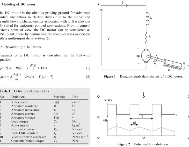
A DC motor consists of stator and armature winding in the rotor as in Fig. 1. The armature winding is supplied with a DC voltage that causes a DC current to flow in the winding.
The field circuit of the motor is excited by a constant source. The steady state speed of the motor can be described as:
x¼ViR K1
ð4Þ wherek1 is the duty cycle. The speed of a DC motor can be
controlled by varying the voltage applied to the terminal. These can be done by using a pulse-width modulation (PWM) technique as shown inFig. 2, whereTis the signal per-iod, tdis the pulse-width, and Vmis the signal amplitude. A
Table 1 Definition of parameters.
No Definition Symbols Unit
1 Rotor speed x(t) rad s1
2 Armature resistance R X
3 Armature inductance L H
4 Armature current i(t) A
5 Armature voltage V(t) v
6 Load torque TL Nm
7 Rotor inertia J kg m2
8 Is torque constant Kt V s rad1 9 Back EMF constant kp V s rad1 10 Viscous friction coefficient D N m s rad1 11 Coulomb friction torque TF N m
Figure 1 Dynamic equivalent circuits of a DC motor.
field voltage signal with varying pulse-width is applied to the motor terminal. The average voltage is calculated from Vag¼ 1 T Z T 0 VðtÞdt¼td TVm¼K1Vm ð5Þ
It can be mentioned from these equation that the average DC component of the voltage signal is linearly related to the pulse-width of the signal, or the duty cycle of the signal, since the period is fixed.
The PWM voltage waveform for the motor is to be obtained by using a special power electronic circuit called a DC chopper. The action done by the DC chopper is supplying a train of unidirectional voltage pulses to the armature wind-ing of the PM-DC motor as shown in Fig. 2. If td is varied
keeping T constant, the resultant voltage wave represents a form of pulse width modulation, and hence the chopper is named as the PWM chopper[6,7].
2.3. Modeling and control of SEDM using MATLAB SimPowerSystems
Fig. 3 shows MATLAB/SimPowerSystems model of a
sepa-rately excited DC motor which has been selected to control
[8]. It consists of a separately excited DC motor fed by a DC source through a chopper circuit. A single GTO thyristor with its control circuit and a free-wheeling diode form the chopper circuit. The motor drives a mechanical load characterized by inertiaJ, friction coefficientB, and load torqueTL. The control
circuit consists of a speed control loop and a current control loop. A proportional-integral (PI) speed control loop senses the actual speed of the motor and compares it with the reference speed to determine the reference armature current required by the motor. One may note that any variation in the actual speed is a measure of the armature current required by the motor. The current control loop consists of a hysteresis current controller (HCC). The block diagram of a hysteresis current controller is shown inFig. 4. HCC is used to generate switching patterns required for the chopper circuit by comparing the actual cur-rent being drawn by the motor with the reference curcur-rent. A
positive pulse is generated if the actual current is less than ref-erence armature current, whereas a negative pulse is produced if the actual current exceeds reference current[9]. In this paper, an adaptive neuro-fuzzy inference system (ANFIS) controller has been proposed for the speed control of separately excited DC motor in the constant torque region, which is detailed in the following part of this paper.
3. Adaptive neuro-fuzzy mode speed controller
3.1. Adaptive neuro-fuzzy principle
A typical architecture of an ANFIS is shown in Fig. 5, in which a circle indicates a fixed node, whereas a square indi-cates an adaptive node. For simplicity, we consider two inputs x,yand one outputz. Among many FIS models, the Sugeno fuzzy model is the most widely applied one for its high inter-pretability and computational efficiency. For a first order Su-geno fuzzy model, a common rule set with two fuzzy if–then rules can be expressed as:
Rule 1: ifxisA1andyisB1, then
z1¼p1xþq1yþr1 ð6Þ
Rule 2: ifxisA2andyisB2, then
z2¼p2xþq2yþr2 ð7Þ
whereAiandBiare the fuzzy sets in the antecedent, andpi,qi
andriare the design parameters that are determined during the
training process. As inFig. 5. The ANFIS consists of five lay-ers[10,11].
The task done by each layer is explained next.
Layer 1: Is composed of a number of computing nodes whose activation functions are fuzzy logic membership functions (triangular functions).
Layer 2: Chooses the minimum value of the inputs. Layer 3: Normalizes each input with respect to the
oth-ers (The ith node output is the ith input divided by the sum of all the other inputs). Layer 4: ith node output is a linear function of the third
layer’sith node output and the ANFIS input signals.
Layer 5: Sums all the incoming signals. The ANFIS structure can be tuned automatically by a least-square estimation (for output member-ship functions) and a back propagation algo-rithm (for output and input membership functions)[11].
3.2. Adaptive neuro-fuzzy controller
The ANFIS controller generates change in the reference volt-ageVref, based on speed erroreand derivate in the speed error Dedefined as:
eðtÞ ¼xrefx ð8Þ
DeðtÞ ¼ ½dðxrefxÞ=dt ð9Þ
wherexrefandxare the reference and the actual speeds. In
this study first order Sugeno type fuzzy inference is used for ANFIS and the typical fuzzy rule is:
IfeisAianddeisBithen z¼fðe;deÞ
where Ai andBi are fuzzy sets in the antecedent and z=f
(e,de) is a crisp function in the consequent. The significances of ANFIS structure are:
Layer 1: Each adaptive node in this layer generates the membership grades for the input vectorsAi,i
= 1, 2, 3. In this paper, the node function is a triangular membership function:
O1i ¼lAiðeÞ ¼ 0 e6ai eai biai ai 6ebi eie eibi bi 6e6ci 0 ei6e 8 > > > < > > > : ð11Þ
Layer 2: The total number of rule is nine in this layer. Each node output represents the activation level of a rule
O1
i ¼Wi¼minðlAiðeÞ lBiðeÞÞ ð12Þ Layer 3: Fixed nodeiin this layer calculates the ratio of the ith rule’s activation level to the total of all activation level:
O3i ¼Wi¼
W Pn
j¼1WJ
ð13Þ Layer 4: Adaptive node i in this layer calculates the contribution of ith rule towards the overall output, with the following node function: O4
i ¼WiZi¼WiðPieþqideþriÞ ð14Þ
Figure 5 Corresponding ANFIS architecture.
Layer 5: The single fixed node in this layer computes the overall output as the sum of each rule’s contribution O5 i ¼ X2 i¼1 WiZi¼ W1Z1þW2Z2 W1þW2 ð15Þ The parameters to be trained areai,biandciof the premise
parameters andpi,qi, andriof the consequent parameters.
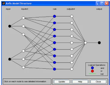
Fig. 6a and b show optimized membership function fore andDeafter raining (Fig. 7). Shows the ANFIS model struc-ture involved in this work.
The number of epochs was 150 for training. The number of MFs for the input variableseanddeis 3 and 3 the number of rules is then 9 (3\3 = 9). The triangular MF is used for two input variables. It is clear from (11) that the triangular MF is specified by two parameters.
Therefore, the ANFIS used here contains a total of 39 fitting parameters, of which 12 (2\3 + 2\3 = 12) are the premise parameters and 27 (3\9 = 27) are the consequent parameters.
4. Simulation results of speed neuro-fuzzy controller
An adaptive neuro fuzzy inference system (ANFIS) controller is simulated for chopper-fed DC motor drive with parameters
as shown inTable 2. The model chosen here for simulation and is taken from[8], where it is simulated and compared to the conventional PI controller. The second section discusses the comparison between conventional PI controller (speed control-ler), fuzzy self tuning PID (FPID) controller (where the
Figure 6 Membership functions for (a) speed error signal and (b) derivative of speed error signal.
conventional PI controller (speed controller) in the chopper-fed DC motor drive was replaced by the self tuning PID controller)[12] and (ANFIS) controller as shown in Fig. 7. The third and last section discusses the effect of increasing temperature on armature resistance of DC motor[13]and its impact on speed (Fig. 8).
4.1. The following observations can be made after demonstration of chopper-fed DC motor drive
Starting the simulation and observing the motor voltage (Va),
current (Ia) and speed (x) on the scope.
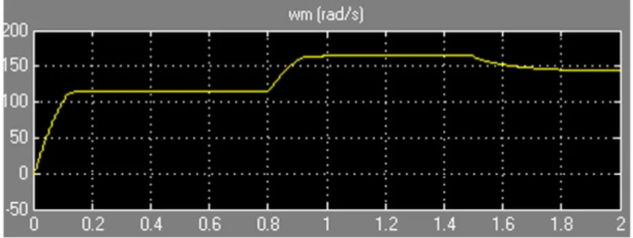
(1) 0 <t< 0.8 s:Starting and steady state operation: Dur-ing this period, the load torque isTL= 5 N m.
(2) t= 0.8 s: Reference speed Step: The reference speed is increased from 120 to 160 rad/s. The PI speed controller regulates the speed in approximately 0.25 s while FPID speed controller regulates the speed in0.07 s and the ANFIS speed controller regulates the speed in0.04 s.
(3) t= 1.5 s:Load torque step:When the load torque is sud-denly increased from 5 to 25 N m[8]the speed is nearly constant for ANFIS, however for PI and FPID the speed is badly affected.
4.2. Comparisons between the conventional PI, FPID and ANFIS controller
The comparisons between the conventional PI, FPID and AN-FIS controller are shown inFigs. 9–11.
Simulation results and comparisons prove that ANFIS per-forms good response where rise time = 0.08 s, at t= 0.8 s (when the reference speed is increased), while for PI speed con-troller = 0.24 s and for FPID speed concon-troller = 0.2 s. 4.3. Temperature effect on SEDM
In all of the electrical machines, the electrical, magnetic and thermal processes are internally coupled together in some sense. The temperature distribution is affected by the proper-ties of the conducting and magnetic materials and the perfor-mance of the electromagnetic force, which is generated from the reaction between stator and rotor. The most temperature sensitive parameters are the winding resistance and the iron core of the stator.
Winding resistance is a major factor in motor selection be-cause it seriously affects Km. Winding resistance and motor
current produce power loss in the form of heat and motor tem-perature rise (TPR). These losses are also referred to as I2R losses and directly degrade motor efficiency.
Most motor windings are copper wire which has a positive temperature coefficient. A winding temperature rise from 25 to 155°C increases wire resistance as much as 50%. Likewise, a proportional decrease in resistance occurs for temperature drops[13].
Table 2 Definition of parameters and its value.
No Definition Symbols Data/unit
1 Shaft power P 5 hp 2 Rated Voltage v 240 (rms)V 3 Armature resistance Ra 0.6 4 Armature inductance La 0.012 H 5 Field resistance Rf 240 H 6 Field inductance Lf 120 7 Moment of inertia J 0.05 kg m2 8 Viscous friction coefficient B 0.2 N m s 9 Coulomb friction torque TF 0.5 N m
The motor resistance increases with temperature as: RaðtÞ ¼Raðt0Þ½1þa0t ð16Þ
where Ra(t) = resistance at 155°C, Ra(t0) = resistance at
25°C, t= rise in temperature and a0= temperature
coeffi-cient of resistance at 0°C = 0.00393 for copper magnet wire. ThenRa(t) = 0.912X.
Figs. 12 and 13show the effect of increasing temperature on speed of DC motor
(1) 0 <t< 0.8 s:Starting and steady state operation: Dur-ing this period, the load torque isTL= 5 N m.
(2)t= 0.8 s: Reference speed step: The reference speed is increased from 120 to 160 rad/s. The PI speed controller regulates the speed in approximately 0.3 s while ANFIS speed controller regulates the speed in0.1 s.
Figure 9 Speed response of pI controller.
Figure 10 Speed response of (FPID) self tuning controller.
Figure 12 Speed response of pI controller under effect of temperature.
(3) t= 1.5 s:Load torque step:When the load torque is sud-denly increased from 5 to 25N m [8] the speed is decreased for both PI and ANFIS but in PI controller the speed is badly affected.
5. Conclusions
Speed controller system based on (ANFIS) controller has been successfully developed using MATLAB (2009) to control the speed of a separately excited DC motor. This paper Lies in the application of (ANFIS) controller to control a separately excited DC motor. This paper also discusses the effect of increasing temperature on armature resistance of DC motor and its impact on speed. The performance of the system has been compared with conventional PI controller and fuzzy self tuning PID controller. An improved speed response has been achieved with the ANFIS than the other techniques men-tioned. The performance has been tested by simulations. There is a reduction in number of ripples as well as steady
state error and rise time and no overshoot appears. Moreover ANFIS controller regulates the speed in time less than previ-ously mentioned controllers and FPID controller as shown in
Table 3.
Actually, the proposed ANFIS speed controller improves the performance in both transient and steady state response in comparison to the conventional PI controller as shown in
Tables 3 and 4.
References
[1] Jang JSR. Adaptive network based fuzzy inference systems. IEEE Trans Syst Man Cybern 1993:665–85.
[2] Santana J, Naredo JL, Sandoval F, Grout I, Argueta OJ. Simulation and construction of a speed control for a DC series motor. Mechatronics 2002;12(9-10):1145–56.
[3] Minkova MD, Minkov D, Rodgerson JL, Harley RG. Adaptive neural speed controller of a dc motor. Electric Power Systems Research 1998;47(2):123–32.
[4] Lima AMN, Cavalcanti JHF, Deep GS. On-line training of adaptive neural network controllers. 20th Int Conf Ind Electron Control Instrum 1994;2(5–9 Sept):1392–5.
[5] Madhusudhana Rao G, Sanker Ram BV. A neural network based speed control for DC motor. Int J Recent Trends Eng 2009;2(6).
[6] Poznyak AS. Adaptive tracking for DC-derivative motor based on motions forgetting. Comput Syst 2001;4(3):205–12.
[7] Rashid MH. Power electronics. New Delhi: Prentic-Hall of India; 1994.
[8] The Mathworks Inc., MATLAB/SimPowerSystems Demos/ Chopper-fed DC Motor Drive version; 2009.
[9] Moleykutty George, Speed control of separately excited DC motor, Faculty of Engineering and Technology, Multimedia University Melaka Campus, 75450 Melaka, Malaysia; 2008. [10] Lin CT, Lee CSG. Neural fuzzy systems: a neuro-fuzzy
synergism to intelligent systems. Upper Saddle River: Prentice-Hall; 1996.
[11] Miloudi1 A, Al-Radadi EA, Draou AD. A variable gain PI controller used for speed control of a direct torque neuro fuzzy controlled induction machine drive. Turk J Elec Eng 2007;15(1):210–5.
[12] Algreer MMF, Kuraz RM. Design fuzzy self tuning of PID controller for chopper-fed DC motor. Drive Al-Rafidain Eng 2008;16(2).
[13] Welch Jr. R, Younkin ., How temperature affects a servomotor’s electrical and mechanical time constants. In Proceedings of the IEEE IAS annual meeting, Pittsburgh, 2002.
Figure 13 Speed response of (ANFIS) under effect of temperature.
Table 3 Comparison results between PI, FPID, and ANFIS controllers.
Control strategies Rise time (s) Time for speed regulation (s) Conventional PI 0.24 0.25
FPID 0.2 0.07
ANFIS 0.08 0.04
Table 4 Comparison results between PI, FPID, and ANFIS controllers. Control strategies Setting time before changing load (s) Setting time after changing load (s) Overshoot Conventional PI 0.58 0.2 Yes FPID 0.2 0.2 No ANFIS 0.09 0.02 No
B.A.A. Omar was working as researcher Assistant, Computer Department and Systems Engineering in Faculty of Engineering, Mansoura University, Egypt from 2005 until now. She got B.Sc. of Computer Engineering and Systems, Faculty of Engineering, Mansoura University in 2005. Her Fields of interest is in Artificial Intelligence, Fuzzy Logics and control systems.
A.Y.M. Haikal was working as researcher, Computer Department and Systems Engi-neering in Faculty of EngiEngi-neering,Mansoura University, Egypt from 1998 to 2002. She worked from 2002 to 2007 as assistant master and she worked as master from 2007 until now. She got B.Sc. of Electronics and Com-munications, Faculty of Engineering, Manso-ura University,Egypt in 1983, M.Sc in Computer and control Systems from Manso-ura University in 2001. She got Ph.D. Engi-neering in Automatic Control from in Faculty of EngiEngi-neering, Mansoura University, Egypt. She supervised many Master degrees in Faculty of Engineering, Mansoura University. Her Fields of interest is in Artificial Intelligence, Fuzzy Logics and control systems.
F.F.G. Areed was working as researcher, Computer Department and Systems Engi-neering in Faculty of EngiEngi-neering, Mansoura University, Egypt from 1970 to 1977. He worked from 1977 to 1982 as assistant master and from 1982 to 1986 he was working as master in Faculty of Engineering, Mansoura University, Egypt. From 1986 to 1993 he worked as assistant professor and from 1993 to 2003 he worked as professor in Faculty of Engineering, Mansoura University, Egypt. In 24/09/2003 he worked as Emeritus Professor. From 1995 to 2004 he worked as Chairman of the Department of Computer and Systems Engineering in Faculty of Engineering, Mansoura University, Egypt. He got B.Sc. in Electrical Power and Machines from Faculty of Engineering, Cairo University in 1970, M.Sc in Computer and control Systems from Mansoura University in 1977. He got Ph.D. Engineering in Automatic Control from Leningrad Russia in 1981. He supervised many Master degrees and Ph.D. in Faculty of Engineering, Mansoura University. His Fields of interest is in Artificial Intelligence, Fuzzy Logics, control systems, Electrical Power and Machines.
![Fig. 3 shows MATLAB/SimPowerSystems model of a sepa- sepa-rately excited DC motor which has been selected to control [8]](https://thumb-us.123doks.com/thumbv2/123dok_us/606551.2572648/3.892.179.708.746.1066/shows-matlab-simpowersystems-model-rately-excited-selected-control.webp)