ISSN: 2302-9285, DOI: 10.11591/eei.v8i1.1399 127
Dynamic evolving neural fuzzy inference system equalization
scheme in mode division multiplexer for optical
fiber transmission
Awab Noori1, Angela Amphawan2, Alaan Ghazi3, S. A. Aljunid Ghazi4 1,2
Optical Computing & Technology Laboratory, School of Computing, University Utara Malaysia, Malaysia 2
Research Laboratory of Electronics, Massachusetts Institute of Technology (MIT), Cambridge, MA, USA 3
School of Human Development & Techno Communication, University Malaysia Perlis, Malaysia 3,4
School of Computer and Communication Engineering, University Malaysia Perlis, Malaysia
Article Info ABSTRACT
Article history: Received Oct 15, 2018 Revised Nov 25, 2018 Accepted Dec 23, 2018
The performance of optical mode division multiplexer (MDM) is affected by inter-symbol interference (ISI), which arises from higher-order mode coupling and modal dispersion in multimode fiber (MMF). Existing equalization algorithms in MDM can mitigate linear channel impairments, but cannot tackle nonlinear channel impairments accurately. Therefore, mitigating the noise in the received signal of MDM in the presence of ISI to recover the transmitted signal is important issue. This paper aims at controlling the broadening of the signal from MDM and minimizing the undesirable noise among channels. A dynamic evolving neural fuzzy inference system (DENFIS) equalization scheme has been used to achieve this objective. Results illustrate that nonlinear DENFIS equalization scheme can improve the received distorted signal from an MDM with better accuracy than previous linear equalization schemes such as recursive‐least‐square (RLS) algorithm. Desirably, this effect allows faster data transmission rate in MDM. Additionally, the successful offline implementation of DENFIS equalization in MDM encourages future online implementation of DENFIS equalization in embedded optical systems.
Keywords: DENFIS Equalization
Inter-symbol interference Mode coupling
Mode division multiplexer Nonlinear
Copyright © 2019 Institute of Advanced Engineering and Science. All rights reserved. Corresponding Author:
Awab Noori,
School of Computing, University Utara Malaysia, 06010 Changlun, Kedah, Malaysia. Email: [email protected]
1. INTRODUCTION
Fibre optic is considered to be the main medium in communication systems that forms the backbone of the Internet [1]. Fibre optic has advantages such as speed of transfer rate. However, single mode fiber transmission capacity is close to its maximum performance limit [2], especially with the increasing demand on cloud computing, social media and big data applications. Therefore improving the performance of multimode fibre using multiplexer is an promising method to transfer huge data to adhere the global demands for the Internet [3]. Multiplexing techniques are used to provide a better performance of multimode fibre and many multiplexing techniques have been implemented in optical system to increase the capacity of transfer rate.
However, most of them have already reached the peak of space limits. An emerging multiplexing technique called Mode Division Multiplexing (MDM) is a promising technique to improve the performance of multimode fiber and increase the rate of data being transferred [3]. However, mode coupling and modal dispersion which causes Inter-Symbol interference (ISI) [1] are inevitable physical issues of mode division
multiplexer that arises because of the imperfection of manufacturing process in multimode fiber [4, 5]. Some modes tend to exchange their powers randomly through spreading inside the fiber, causing inter-symbol interference between modes [3, 6]. This will lead signals to overlap with each other. As a result, at the receiver side, it will be difficult to decode or recover the transmitted signal correctly. Consequently, the error rate increases and the data rate decreases, which causes a huge loss of data throughput. To mitigate the unwanted impact of ISI in MDM, one approach is to reshape the received signal to improve it and mitigate the effect of noise. This method is known as equalization [1]. Furthermore, current equalization techniques in MDM are mostly based on recursive least squares (RLS) and least mean squares (LMS) algorithms.
LMS algorithm is a class of adaptive filter used to mimic a desired filter by finding the filter coefficients that relate to producing the least mean squares of the error signal which is the difference between the desired and the distorted signal [7]. RLS adaptive filter is an algorithm which recursively finds the filter coefficients that minimize a weighted linear least squares cost function relating to the input signals. This in contrast to other algorithms such as LMS that aim to reduce the mean square error. The RLS has fast convergence time. However, this benefit comes at the cost of high computational complexity, and potentially poor tracking performance when the filter to be estimated changes [7, 8]. However, these algorithms can solve the linear distortion but cannot deal with nonlinear distortion beside suffering from several performance limitations such as slow convergence, a large number of iterations and a long training time [9]. This paper proposes an equalization scheme based on dynamic evolving neural-fuzzy inference system (DENFIS) [10] to mitigate the nonlinear dispersion represented by mode coupling and Inter-symbol interference.
DENFIS enhance and inherits the features of other models which make DENFIS suitable for online and offline adaptive systems [11]. DENFIS uses Takagi-Sugeno type of fuzzy inference engine. Because it is more compact and computationally efficient representation than a Mamdani system [28]. DENFIS is recommended for prediction applications [12]. When unknown data becomes available, DENFIS will adapt its structure and extract the output. Moreover, the DENFIS creates rules through the learning process. In DENFIS, clusters of data are created based on a similarity between data samples in the input space. If samples that have a distance to an existing neural node (cluster center, rule node) less than a certain threshold are allocated to the same cluster. For samples that do not fit into existing clusters, these samples will be added to form new clusters. Cluster center continues adjusting itself according to new data samples, and new clusters will be created incrementally. Recently, DENFIS used in numerous domains of scientific research like financial market implementation for Stock trading with series [13], tool wear surveillance [14]. Time-series prediction [15], software reliability prediction [16], solving regression problems using publicly available benchmark datasets for regression analysis from the University of California, Irvine (UCI) machine learning repository and StatLib repository [17], runoff forecasting [18], modelling coagulant dosage in water treatment plant [19]. Although DENFIS has remarkable successes in different fields.
To the best of the authors knowledge, using DENFIS as an equalization scheme in MDM over MMF is the first study in the literature. Therefore, the present study apply DENFIS method in MDM over MMF to mitigate the ISI effects in the received channel impulse response. Section 2 provided a general overview of DENFIS algorithm and literature. Section 3 illustrated the design of mode division multiplexing (MDM) to comprehend its characteristics. The equalization process mentioned in Section 4. Section 5 provides results and discussion of DENFIS equalization scheme. The implementation of RLS and its results beside a comparison with DENFIS results has been illustrated in Section 6. Section 7 conclude this paper.
2. RESEARCH METHOD
Dynamic evolving neural-fuzzy inference system (DENFIS) was introduced by Kasabov and Song [10]. DENFIS evolves through incremental, hybrid learning, and accommodate new input data, including new features, new classes, etc., through local element tuning. New fuzzy rules are produced and updated during the process of the system. Within time interval, the output of DENFIS is calculated through a fuzzy inference system based on m-most activated fuzzy rules, these fuzzy rules are dynamically chosen from a fuzzy rule set. A set of fuzzy rules can be integrated in DENFIS before or during its learning process. Fuzzy rules can also be extracted during or after the learning process [10, 20]. An ECM is utilize DENFIS method to split the input space for the creating the fuzzy rules [21]. DENFIS is utilized for online and offline learning. In the online model of DENFIS, the linear function in the consequent parts are created and updated through learning from data using a least square estimator [10]. In the online mode, the fuzzy rules in the rule set can also be updated as new training data appear in the system [22]. DENFIS offline was proposed together with the online version of DENFIS, which sacrifices the dynamic evolving aspect of the DENFIS algorithm and replaces it with more sophisticated learning algorithm to provide higher accuracy. It has shown improvement in prediction accuracy [23]. The design of mode division multiplexing system has been done by using OptSim 5.2 simulator [24].
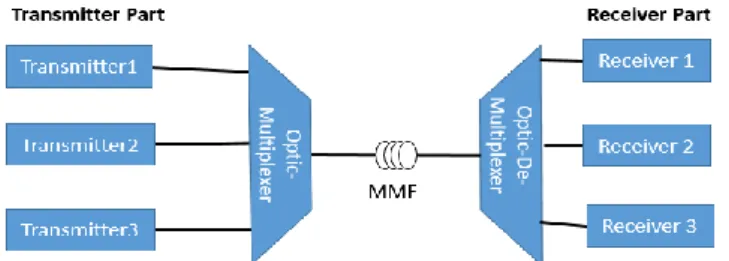
The proposed MDM spot mode model is illustrated in Figure 1. Three channels have been sent with total data rate 90 G/s over 5 km distance. The MDM spot model comprises of three distinct phases the input, processing phase, and the output phase. Furthermore, to determine the reference signal to be used in the DENFIS equalization scheme, distorted signal must be collected from simulated MDM.
Figure 1. Mode division multiplexer model
The design is executed. Three channels have been implemented namely Channel 1, Channel 2 and Channel 3 respectively. These channels are combined and sent to its destination. After modeling the MDM and executing it in the simulation, distorted signal has been gathered from the MDM. Then, has prepared to be suitable for equalization process. The next sections show why performing signal preparation is important and how will be implemented. The collected signal or distorted signal from the MDM model consists of three channels. Each channel has different value range between 0 and 1. This value represents the power coefficient of signal. Moreover, the collected signals have a very severe distortion and the power units scattered overall the input space of each channel. Furthermore, there are overlapping between the channels which lead to Inter-Symbol Interference (ISI) and ISI consider as non-linear dispersion or high order distortion. In other words, each channel interferes with a time interval of another channel.
However, DENFIS equalization scheme cannot function with the distorted signal only. To make DENFIS equalization scheme possible, DENFIS, equalization scheme requires a desired or reference signal. This reference signal will be used in DENFIS equalization to reshape the distorted signal during the equalization running process. The aim of implementing the reference signal is to use it as pulse shaping with DENFIS equalization scheme to mitigate distortion represented by ISI in the received signal as have been mentioned earlier above. The design of ideal status for the received channel impulse response can be done by using the Gaussian pulse shaping filter as illustrated in (1). This pulse shaping filter is one of filters used to represent the ideal signal in communication systems [25]. Furthermore, the Gaussian pulse is used because the optical sources have a distribution of power with a wavelength that is approximately Gaussian distribution in the form [26]. The reference signal is represented as (1).
( )
√
( ) ( )
(1)
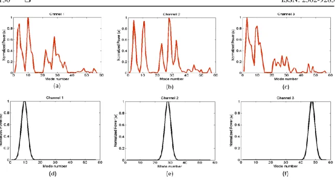
where x is the mode number which will be based on the modes number that arrived at receiver, μ is the mode at which the reference signal is maximum and also it is median of each channel. Moreover, σ is standard deviation which is the reference signal width, in the reference signal, standard deviation is σ = 2, the value of standard deviation has been determined depend on the collected modes number and number of channels. Furthermore, in this scenario the standard deviation value cannot be but 2 because choosing higher or lower value will make the reference signal not accurate enough to include all the data points in the input space. This parameter mentioned above have been implemented in MATLAB r2013b to produce three reference channels and map those channels with the three channels that have collected from the MDM system. As a result, each channel is assigned to its distorted signal as illustrated in Figure 2. Furthermore, each channel has its time interval so it will be no overlapping between these channels.
Data normalization process needed to make this channel impulse response suitable for this study. Data normalization has been applied in both distorted and desired signals. Data normalization is a process where distorted signal, which brought from MDM system model should be fitted with the reference signal or be in same range. In this paper min and max, normalization is used. The min and max of the signal values are 0 and one as shown in (2) where the actual value is x, the minimum value in the range is x_min and x_max is the maximum value in the range [27].
Figure 2. Normalized channels: (a), (b), (c) Distorted signals (d), (e), (f) Reference signals
where x the value of distorted signal or reference signal, x_min is the minimum value in signal and x_max is the maximum value of signal. Figure 2 illustrates the normalized distorted signal and the normalized reference signal after normalization process. Data normalization is an important process which will make sure that no values will be ignored inside the input space.
DENFIS implementation begins with entering the distorted signal along with reference signal to each channel individually. Then the value for Dthr (i.e. Dthr is a threshold value defined at the beginning of the process which will determine the number of clusters that will create parameter has been specified as standard values. DENFIS method was applied by using program codes with an interface written in MATLAB r2013b [28]. This code obtained from the Knowledge Engineering and Discovery Research Institute (KEDRI) (http://www.aut.ac.nz/research/research institutes/kedri/books).
3. RESULTS AND ANALYSIS
Different results from various channels have been discussed and analyzed in term of the shape of signal, RMSE and the time interval for each channel before and after DENFIS equalization. DENFIS equalization scheme simulated for the distorted signal of three different channels. The results of three channels can be summarized in Table 1. The table illustrates the values before DENFIS equalization and after applying DENFIS equalization. Furthermore, RMSE has been used to measure the performance.
Table 1. The results of DENFIS equalization scheme for the three channels
No Dthr N of R Iteration RMSE (before) RMSE (after)
Ch1 0.001 43 30 0.2119 0.0365
Ch2 0.0001 52 30 0.2124 0.0294
Ch3 0.0001 53 40 0.2376 0.0356
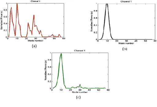
Figure 3(a) presents the distorted signal of Channel 1 before the implementation of DENFIS. DENFIS equalization used reference signal to mitigate the distortion in the Channel 1 as seen in Figure 3(b). The result of the equalized signal for Channel 1 is illustrated in Figure 3(c) after applying the DENFIS equalization scheme. In Figure 3 the equalization process in Channel 1 was performed and the nonlinear distortion represented by ISI is dramatically decreased. This can be noticed by seeing the shape of signal of equalized signal as illustrated in Figure 3(c). Furthermore, the modes or data points of the equalized signal are centered in their proper position, so there is no overlapping with other signals. The results indicated that Channel 1 required less number of rules and fewer iteration numbers because most of Channel 1 values positioned in the Channel 1-time interval or near of it, because the distortion amount in the distorted signal of
Channel 1 before equalization was assembled mostly between 1 and 40 modes period as shown in Figure 3(a).
Figure 3. Effect of equalization on signals: (a) Distorted signal for Channel 1 (b) Reference signal 1 for Channel 1 (c) Equalized signal for Channel 1 using DENFIS
However, the distortion value in the equalized signal of Channel 1 after equalization was focused in Channel 1-time interval as shown in Figure 3(c). However, there was still a little distortion in the equalized signal of Channel 1 and cannot be eliminated. The result of Channel 2 and its improved signal have been illustrated in Figure 4(a) before the equalization, and Figure 4(c) shows the shape of Channel 2 after DENFIS equalization. The equalization process in Channel 2 provides the best RMSE result which indicates a real improvement in the shape of signal and no overlapping between different signals as shown in Figure 4(c).
Figure 4. Effect of equalization on signal (a) Distorted signal for Channel 2 (b) Reference signal 2(c) Equalized signal for Channel 2 using DENFIS
Moreover, the form of equalized signal has almost the same shape as reference signal as seen in Figure 4(b). The result presented that Channel 2 used 52 number of rules which means Dthr has created and updated 52 cluster centers during the equalization process, and 30 iteration numbers because most of Channel 2 values positioned in the Channel 2 modes period. According to the Figure 4(a), the distortion amount in the distorted signal of Channel 2 before equalization was assembled mostly between 1 and 15 modes period from the left side of Channel 2 and from 36 to 50 in the right side of Channel 2. However, the distortion value in the equalized signal of Channel 2 after equalization was centralized in Channel 2 period as can be seen in Figure 4(b). Moreover, there was still a little distortion in the equalized signal of Channel 2 and cannot be totally mimic the reference signal. The result of Channel 3 before equalization and its response after applying the DENFIS equalization as shown in Figure 5(c). The result in numbers can be seen in Table 1 with the values of the parameters that have been used for each channel. Table 1 shows the value of Channel 3 before and after applying DENFIS equalization scheme.
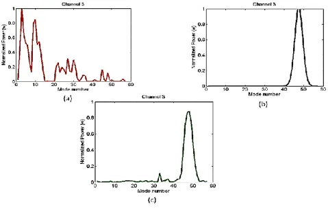
In Figure 5 the equalization process for Channel 3 improved the shape of signal significantly and the points in the input space integrated under the Channel 3-time interval as shown in Figure 5(c). This indicates that the effect if ISI in this channel has been mitigated and no more overlapping between channels. The results illustrate that Channel 3 provide a good RMSE result but at a cost of a high number of rules and many iterations. According to the Figure 5(a), the distortion amount in the distorted signal of Channel 3 before equalization was assembled mostly between 1 modes period and 17 modes period from the left side of Channel 3 and from 20 to 35 for the same side. Furthermore, there was still a little distortion in the equalized signal of Channel 3.
Figure 5. Effect of equalization on signals (a) Distorted signal for Channel 3 (b) Reference signal 3 for Channel 3 (c) Equalized signal for Channel 3 using DENFIS
According to the previous results discussion of channels that have been mentioned above, it can conclude that the scattering of data points in the input space has a significant impact to decrease the RMSE value. That is mean that scattering or spreading of data points in the input space is high, then the RMSE after equalization will be minimized sharply. The reason of this that ECM algorithm will be able to produce a greater number of clusters which will lead to increase the number of rules in DENFIS. So the more spread of data points, the lower root main square error. In other hand, the performance of recursive‐least‐square (RLS) algorithm in terms of convergence rate, and stability depends on the forgetting factor. The parameters that used in this experience to minimize the RMSE are the data collection from the simulation design consist of three channels used with three reference signals for each channel. Number of weights, initialization Parameter and forget factor.
The same for this equalization scheme the distorted signal and reference signal for different three channels have been imported. The imported channels are the same channels that have been used in DENFIS equalization scheme. Although RLS algorithm provides better channel impulse response for the different three channels, yet the values of RMSE is not minimized significantly as can be seen in Table 2. This is
because RLS algorithm work to minimize the weight, whereas DENFIS is working on update the rules or creating new ones. As a result, the appearance of ISI as a nonlinear distortion is resident. Furthermore, the interference between channels is the main obstacle to applying RLS to tackle the nonlinear distortions.
Table 2. Recursive least squares results
No NO. OF WEIGHTS F. Factor Initialization Parameter RMSE (before) RMSE (after)
Ch1 15 0.6 0.612 0.2624 0.1428
Ch2 15 0.9 0.112 0.2898 0.2382
Ch3 9 0.1 0.912 0.3766 0.1932
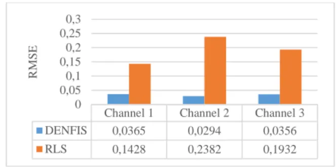
The proposed DENFIS equalization scheme has been evaluated by comparing its results with RLS algorithm results which consider as another similar algorithm. To observe the effect of DENFIS equalization scheme to the RMSE. The results of the comparison show that DENFIS perform better than RLS in term of RMSE rate for Channel 1, Channel 2 and Channel 3 as illustrated in Figure 6. The figure described that DENFIS produced butter results comparing with RLS as shown in Figure 6. Moreover, DENFIS equalization scheme can reshape the signal of the received signal with the appearance of severe ISI in the channels to be almost like the original transmitted signal.
Figure 6. Comparison between RLS and DENFIS results
4. CONCLUSION
ISI is the main obstacle that faces MDM in MMF transmission. Equalization is applied to tackle this challenge. However, the existing equalization schemes has drawbacks too. which it can solve the liner distortion but not non-liner distortion. The main goal of this research is minimizing the unwanted distortion represented by ISI in MDM over MMF. DENFIS is used to fulfil this goal. The research result shows that DENFIS as equalization scheme for the transmitted signal in fiber optic system over multimode fiber is possible. In addition, result indicates that the proposed DENFIS equalization scheme has superior accuracy with an average of RMSE of 0.0338 and outperformed linear RLS equalization schemes with high average RMSE values of 0.1914. For future work, online implementation of DENFIS equalization scheme for MDM will be promising scheme. Because applying offline DENFIS equalization scheme for MDM was successful as shown in the results of this research. This may promise a higher transfer rate in MDM system. Moreover, beside using RMSE for validation, it will be recommended to use another validation method such as: the correlation coefficients (r), coefficient of determination (R2), Variance-Accounted-For (%VAF).
REFERENCES
[1] S. O. Arik, J. M. Kahn, and K.-P. Ho, "MIMO signal processing for mode-division multiplexing: An overview of channel models and signal processing architectures," Signal Processing Magazine, IEEE, vol. 31, pp. 25-34, 2014. [2] D. K. S. Tripathi, Pallavi Shukla, Narendra Krdixit, Hemant Kr, "Investigations with mode division multiplexed
transmission," International Journal of Advances in Engineering Sciences, vol. 4, pp. 1-4, 2014. [3] S. Ö. A. a. J. M. Kahn, "Diversity-multiplexing tradeoff in mode-division multiplexing," 2014.
[4] G. Li, N. Bai, N. Zhao, and C. Xia, "Space-division multiplexing: the next frontier in optical communication," Advances in Optics and Photonics, vol. 6, pp. 413-487, 2014.
[5] K. Shi and B. C. Thomsen, "Sparse Adaptive Frequency Domain Equalizers for Mode-Group Division Multiplexing," Journal of Lightwave Technology, vol. 33, pp. 311-317, 2015.
[6] K.-P. Ho and J. M. Kahn, "Linear propagation effects in mode-division multiplexing systems," Lightwave Technology, Journal of, vol. 32, pp. 614-628, 2014.
Channel 1 Channel 2 Channel 3
DENFIS 0,0365 0,0294 0,0356 RLS 0,1428 0,2382 0,1932 0 0,05 0,1 0,15 0,2 0,25 0,3 R M S E
[7] G. Malik and A. S. Sappal, "Adaptive equalization algorithms: an overview," International Journal of Advanced Computer Science and Applications, vol. 2, 2011.
[8] G. Iliev and N. Kasabov, "Channel equalization using adaptive filtering with averaging," 5th Joint coference on Information Science (JCIS), Atlantic city, USA, vol. 14, p. 2009, 2000.
[9] A. A. Elbibas, I. M. Ellabib, and Y. Hwegy, "Neuro-Fuzzy Network for Equalization of Different Channel Models," channels, vol. 2, p. 3, 2013.
[10]N. K. Kasabov and Q. Song, "DENFIS: dynamic evolving neural-fuzzy inference system and its application for time-series prediction," Fuzzy Systems, IEEE Transactions on, vol. 10, pp. 144-154, 2002.
[11]N. K. Kasabov, "Evolving connectionist systems for adaptive learning and knowledge discovery: Trends and directions," Knowledge-Based Systems, vol. 80, pp. 24-33, 2015.
[12]S. Soltic, S. Pang, N. Kasabov, S. Worner, and L. Peackok, "Dynamic neuro-fuzzy inference and statistical models for risk analysis of pest insect establishment," in Neural Information Processing, 2004, pp. 971-976.
[13]Z. Tan, C. Quek, and P. Y. Cheng, "Stock trading with cycles: A financial application of ANFIS and reinforcement learning," Expert Systems with Applications, vol. 38, pp. 4741-4755, 2011.
[14]A. Gajate, R. Haber, R. Del Toro, P. Vega, and A. Bustillo, "Tool wear monitoring using neuro-fuzzy techniques: a comparative study in a turning process," Journal of Intelligent Manufacturing, vol. 23, pp. 869-882, 2012.
[15]D. Dovžan and I. Škrjanc, "Recursive fuzzy c-means clustering for recursive fuzzy identification of time-varying processes," ISA transactions, vol. 50, pp. 159-169, 2011.
[16]R. Mohanty, V. Ravi, and M. R. Patra, "Software reliability prediction using group method of data handling," in Rough Sets, Fuzzy Sets, Data Mining and Granular Computing, ed: Springer, 2009, pp. 344-351.
[17]M. Farquad, V. Ravi, and S. B. Raju, "Support vector regression based hybrid rule extraction methods for forecasting," Expert Systems with Applications, vol. 37, pp. 5577-5589, 2010.
[18]A. Talei, L. H. C. Chua, C. Quek, and P.-E. Jansson, "Runoff forecasting using a Takagi–Sugeno neuro-fuzzy model with online learning," Journal of Hydrology, vol. 488, pp. 17-32, 2013.
[19]S. Heddam and N. Dechemi, "A new approach based on the dynamic evolving neural-fuzzy inference system (DENFIS) for modelling coagulant dosage (Dos): case study of water treatment plant of Algeria," Desalination and Water Treatment, vol. 53, pp. 1045-1053, 2015.
[20]N. Kasabov, Q. Song, and T. M. Ma, "Fuzzy-neuro systems for local and personalized modelling," in Forging New Frontiers: Fuzzy Pioneers II, ed: Springer, 2008, pp. 175-197.
[21]M. J. Watts, "Evolving connectionist systems: Characterisation, simplification, formalisation, explanation and optimisation," 2004.
[22]N. Kasabov and B. Woodford, "Rule insertion and rule extraction from evolving fuzzy neural networks: algorithms and applications for building adaptive, intelligent expert systems," in Fuzzy Systems Conference Proceedings, 1999. FUZZ-IEEE'99. 1999 IEEE International, 1999, pp. 1406-1411.
[23]Y.-C. Hwang and Q. Song, "Dynamic neural fuzzy inference system," in Advances in Neuro-Information Processing, ed: Springer, 2008, pp. 1245-1250.
[24]RSoft, "Synopsys RSoft Solutions," 2015.
[25]P. Agrawal, R. Mehra, and M. Singh, "Implementation cost & performance analysis of pulse shaping filter," in Green Computing and Internet of Things (ICGCIoT), 2015 International Conference on, 2015, pp. 1168-1172. [26]S. Lawan, M. Ajiya, and D. Shu'Aibu, "Numerical simulation of chromatic dispersion and fiber attenuation in a
single-mode optical fiber system," Signal, vol. 10, p. 3, 2012.
[27]L. A. Y. Alrabady, "An online-integrated condition monitoring and prognostics framework for rotating equipment," 2014.
[28]Matlab, "The Language of Technical Computing," 2014.
BIOGRAPHIES OF AUTHORS
Awab Noori received his Bachelor dgree in Computer Science from the University of Since and thenology (UST), Yemen in 2007 and Master of Science in Information Technology with from University of Northern Malaysia (UUM), Malaysia in 2017. He is currently a PhD candedate in School of Computing of the same university.
Angela Amphawan received her PhD in Engineering from University of Oxford. she is an Associate Professor of optical technology at School of Computing, University of Northern Malaysia (UUM) and Head of the university’s Optical Technology Research Laboratory. She is also a Fulbright Research Fellow at Massachusetts Institute of Technology, Cambridge, USA. Her Research Interest in Optical Fibre, Free-space Optics, Radio-over-Free Space Optics.
Alaan Ghazi Mohammed received his bachelor’s in computer science from the University of Kirkuk, Iraq in 2013 and Master of Science in Information Technology with specialization in (Fiber Optics) from University of Northern Malaysia (Universiti Utara Malaysia), Malaysia in 2016. He is currently a PhD Student in Communication and Information Technology at School of Human Development and Techno-communication, Universiti Malaysia Perlis. His research interests include OCDMA technologies, wavelength division multiplexing, mode division multiplexer, and optical signal processing.
Syed Alwee Aljunid received the B.Eng in Computer and Communication System (First Class Honor) and PhD in Communication and Network Engineering from University Putra Malaysia, Malaysia in 2001 and 2005, respectively. He is currently a Professor and Deputy Dean (Academic and Research) of the School of Computer and Communication Engineering, Northern Malaysia University College of Engineering (KUKUM), Perlis, Malaysia. His research interests include OCDMA technologies and wavelength division multiplexing.