OMNeT++
User Manual
Version 4.6
Chapters
Contents v
1 Introduction 1
2 Overview 3
3 The NED Language 11
4 Simple Modules 47
5 Messages and Packets 119
6 Message Definitions 129
7 The Simulation Library 151
8 Network Graphics And Animation 199
9 Building Simulation Programs 213
10 Configuring Simulations 221
11 Running Simulations 239
12 Result Recording and Analysis 255
13 Eventlog 267
14 Documenting NED and Messages 271
15 Testing 279
16 Parallel Distributed Simulation 293
A NED Reference 321
B NED Language Grammar 349
C NED XML Binding 365
D NED Functions 373
E Message Definitions Grammar 379
F Display String Tags 387
G Configuration Options 391
H Result File Formats 403
I Eventlog File Format 411
References 417
Contents
Contents v
1 Introduction 1
1.1 What Is OMNeT++? . . . 1
1.2 Organization of This Manual . . . 2
2 Overview 3 2.1 Modeling Concepts . . . 3
2.1.1 Hierarchical Modules . . . 4
2.1.2 Module Types . . . 4
2.1.3 Messages, Gates, Links . . . 5
2.1.4 Modeling of Packet Transmissions . . . 5
2.1.5 Parameters . . . 5
2.1.6 Topology Description Method . . . 6
2.2 Programming the Algorithms . . . 6
2.3 Using OMNeT++ . . . 6
2.3.1 Building and Running Simulations . . . 6
2.3.2 What Is in the Distribution . . . 8
3 The NED Language 11 3.1 NED Overview . . . 11
3.2 NED Quickstart . . . 12
3.2.1 The Network . . . 12
3.2.2 Introducing a Channel . . . 14
3.2.3 The App, Routing, and Queue Simple Modules . . . 14
3.2.4 The Node Compound Module . . . 15
3.2.5 Putting It Together . . . 17
3.3 Simple Modules . . . 17
3.4 Compound Modules . . . 19
3.7 Gates . . . 29
3.8 Submodules . . . 30
3.9 Connections . . . 32
3.10 Multiple Connections . . . 34
3.10.1Connection Patterns . . . 36
3.11 Parametric Submodule and Connection Types . . . 37
3.11.1Parametric Submodule Types . . . 37
3.11.2Parametric Connection Types . . . 39
3.12 Metadata Annotations (Properties) . . . 39
3.13 Inheritance . . . 42
3.14 Packages . . . 42
4 Simple Modules 47 4.1 Simulation Concepts . . . 47
4.1.1 Discrete Event Simulation . . . 47
4.1.2 The Event Loop . . . 48
4.1.3 Events and Event Execution Order in OMNeT++ . . . 48
4.1.4 Simulation Time . . . 49
4.1.5 FES Implementation . . . 50
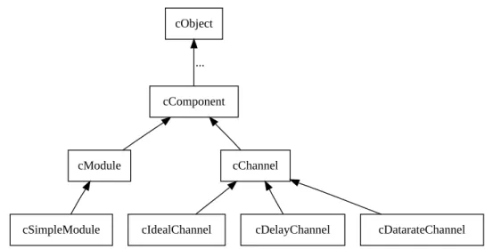
4.2 Components, Simple Modules, Channels . . . 50
4.3 Defining Simple Module Types . . . 52
4.3.1 Overview . . . 52
4.3.2 Constructor . . . 53
4.3.3 Initialization and Finalization . . . 53
4.4 Adding Functionality to cSimpleModule . . . 56
4.4.1 handleMessage() . . . 56
4.4.2 activity() . . . 61
4.4.3 How to Avoid Global Variables . . . 66
4.4.4 Reusing Module Code via Subclassing . . . 66
4.5 Accessing Module Parameters . . . 67
4.5.1 Volatile and Non-Volatile Parameters . . . 67
4.5.2 Changing a Parameter’s Value . . . 69
4.5.3 Further cPar Methods . . . 69
4.5.4 Emulating Parameter Arrays . . . 70
4.5.5 handleParameterChange() . . . 70
4.6 Accessing Gates and Connections . . . 71
4.6.1 Gate Objects . . . 71
4.7 Sending and Receiving Messages . . . 76
4.7.1 Self-Messages . . . 77
4.7.2 Sending Messages . . . 78
4.7.3 Broadcasts and Retransmissions . . . 79
4.7.4 Delayed Sending . . . 80
4.7.5 Direct Message Sending . . . 81
4.7.6 Packet Transmissions . . . 82
4.7.7 Receiving Messages with activity() . . . 84
4.8 Channels . . . 86
4.8.1 Overview . . . 86
4.8.2 The Channel API . . . 86
4.8.3 Channel Examples . . . 88
4.9 Stopping the Simulation . . . 89
4.9.1 Normal Termination . . . 89
4.9.2 Raising Errors . . . 89
4.10 Finite State Machines . . . 90
4.11 Navigating the Module Hierarchy . . . 94
4.12 Direct Method Calls Between Modules . . . 96
4.13 Dynamic Module Creation . . . 97
4.13.1When Do You Need Dynamic Module Creation . . . 97
4.13.2Overview . . . 97
4.13.3Creating Modules . . . 98
4.13.4Deleting Modules . . . 99
4.13.5Module Deletion and finish() . . . 99
4.13.6Creating Connections . . . 100
4.13.7Removing Connections . . . 101
4.14 Signals . . . 101
4.14.1Design Considerations and Rationale . . . 102
4.14.2The Signals Mechanism . . . 102
4.14.3Listening to Model Changes . . . 107
4.15 Signal-Based Statistics Recording . . . 109
4.15.1Motivation . . . 109
4.15.2Declaring Statistics . . . 110
4.15.3Statistics Recording for Dynamically Registered Signals . . . 114
4.15.4Adding Result Filters and Recorders Programmatically . . . 115
4.15.5Emitting Signals . . . 116
5.1 Overview . . . 119
5.2 The cMessage Class . . . 120
5.2.1 Basic Usage . . . 120
5.2.2 Duplicating Messages . . . 121
5.2.3 Message IDs . . . 122
5.2.4 Control Info . . . 122
5.2.5 Information About the Last Arrival . . . 122
5.2.6 Display String . . . 123
5.3 Self-Messages . . . 123
5.3.1 Using a Message as Self-Message . . . 123
5.3.2 Context Pointer . . . 124
5.4 The cPacket Class . . . 124
5.4.1 Basic Usage . . . 124
5.4.2 Identifying the Protocol . . . 124
5.4.3 Information About the Last Transmission . . . 125
5.4.4 Encapsulating Packets . . . 125
5.4.5 Reference Counting . . . 126
5.4.6 Encapsulating Several Packets . . . 126
5.5 Attaching Parameters and Objects . . . 127
5.5.1 Attaching Objects . . . 127
5.5.2 Attaching Parameters . . . 127
6 Message Definitions 129 6.1 Introduction . . . 129
6.1.1 The First Message Class . . . 129
6.2 Messages and Packets . . . 130
6.2.1 Defining Messages and Packets . . . 130
6.2.2 Field Data Types . . . 131
6.2.3 Initial Values . . . 132
6.2.4 Enums . . . 132
6.2.5 Fixed-Size Arrays . . . 133
6.2.6 Variable-Size Arrays . . . 133
6.2.7 Classes and Structs as Fields . . . 134
6.2.8 Pointer Fields . . . 134
6.2.9 Inheritance . . . 135
6.2.10Assignment of Inherited Fields . . . 135
6.3 Classes . . . 136
6.6 Using C++ Types . . . 138
6.6.1 Announcing Types to the Message Compiler . . . 138
6.6.2 Making the C++ Declarations Available . . . 139
6.6.3 Putting it Together . . . 139
6.7 Customizing the Generated Class . . . 140
6.7.1 Customizing Method Names . . . 140
6.7.2 Customizing the Class via Inheritance . . . 141
6.7.3 Abstract Fields . . . 142
6.8 Using Standard Container Classes for Fields . . . 143
6.8.1 Typedefs . . . 143
6.8.2 Abstract Fields . . . 144
6.9 Namespaces . . . 146
6.9.1 Declaring a Namespace . . . 146
6.9.2 C++ Blocks and Namespace . . . 146
6.9.3 Type Announcements and Namespace . . . 147
6.10 Descriptor Classes . . . 148
6.11 Summary . . . 149
7 The Simulation Library 151 7.1 Class Library Conventions . . . 152
7.1.1 Base Class . . . 152
7.1.2 Setting and Getting Attributes . . . 152
7.1.3 getClassName() . . . 152
7.1.4 Object Names . . . 152
7.1.5 Object Full Name and Full Path . . . 153
7.1.6 Copying and Duplicating Objects . . . 154
7.1.7 Iterators . . . 154
7.1.8 Error Handling . . . 154
7.2 Logging from Modules . . . 155
7.3 Simulation Time Conversion . . . 155
7.4 Generating Random Numbers . . . 156
7.4.1 Random Number Generators . . . 156
7.4.2 Random Number Streams, RNG Mapping . . . 157
7.4.3 Accessing The RNGs . . . 158
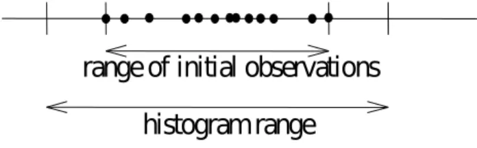
7.4.4 Random Variates . . . 158
7.4.5 Random Numbers from Histograms . . . 159
7.5 Container Classes . . . 159
7.6 Routing Support: cTopology . . . 162 7.6.1 Overview . . . 162 7.6.2 Basic Usage . . . 163 7.6.3 Shortest Paths . . . 165 7.7 Pattern Matching . . . 166 7.7.1 cPatternMatcher . . . 166 7.7.2 cMatchExpression . . . 168
7.8 Statistics and Distribution Estimation . . . 170
7.8.1 cStatistic and Descendants . . . 170
7.8.2 Distribution Estimation . . . 171
7.8.3 The k-split Algorithm . . . 174
7.8.4 Transient Detection and Result Accuracy . . . 176
7.9 Recording Simulation Results . . . 177
7.9.1 Output Vectors: cOutVector . . . 177
7.9.2 Output Scalars . . . 178
7.10 Watches and Snapshots . . . 179
7.10.1Basic Watches . . . 179
7.10.2Read-write Watches . . . 180
7.10.3Structured Watches . . . 180
7.10.4STL Watches . . . 181
7.10.5Snapshots . . . 181
7.10.6Getting Coroutine Stack Usage . . . 183
7.11 Defining New NED Functions . . . 183
7.11.1Define_NED_Function() . . . 184
7.11.2Define_NED_Math_Function() . . . 188
7.12 Deriving New Classes . . . 189
7.12.1cOwnedObject or Not? . . . 189
7.12.2cOwnedObject Virtual Methods . . . 190
7.12.3Class Registration . . . 191
7.12.4Details . . . 191
7.13 Object Ownership Management . . . 194
7.13.1The Ownership Tree . . . 194
7.13.2Managing Ownership . . . 195
8 Network Graphics And Animation 199 8.1 Display Strings . . . 199
8.1.1 Display String Syntax . . . 199
8.1.4 Display String Tags Used in Submodule Context . . . 201
8.1.5 Display String Tags Used in Module Background Context . . . 205
8.1.6 Connection Display Strings . . . 206
8.1.7 Message Display Strings . . . 207
8.2 Parameter Substitution . . . 208
8.3 Colors . . . 208
8.3.1 Color Names . . . 208
8.3.2 Icon Colorization . . . 208
8.4 Icons . . . 209
8.4.1 The Image Path . . . 209
8.4.2 Categorized Icons . . . 209
8.4.3 Icon Size . . . 210
8.5 Layouting . . . 210
8.6 Enhancing Animation . . . 211
8.6.1 Changing Display Strings at Runtime . . . 211
8.6.2 Bubbles . . . 212
9 Building Simulation Programs 213 9.1 Overview . . . 213
9.2 Using gcc . . . 215
9.2.1 The opp_makemake Tool . . . 215
9.2.2 Basic Use . . . 215
9.2.3 Debug and Release Builds . . . 216
9.2.4 Debugging the Makefile . . . 216
9.2.5 Using External C/C++ Libraries . . . 216
9.2.6 Building Directory Trees . . . 217
9.2.7 Automatic Include Dirs . . . 217
9.2.8 Dependency Handling . . . 217
9.2.9 Out-of-Directory Build . . . 217
9.2.10Building Shared and Static Libraries . . . 218
9.2.11Recursive Builds . . . 218
9.2.12Customizing the Makefile . . . 219
9.2.13Projects with Multiple Source Trees . . . 219
9.2.14A Multi-Directory Example . . . 219
10 Configuring Simulations 221 10.1 The Configuration File . . . 221
10.1.3File Inclusion . . . 223
10.2 Sections . . . 223
10.2.1The [General] Section . . . 223
10.2.2Named Configurations . . . 224
10.2.3Section Inheritance . . . 224
10.3 Assigning Module Parameters . . . 226
10.3.1Using Wildcard Patterns . . . 226
10.3.2Using the Default Values . . . 227
10.4 Parameter Studies . . . 228
10.4.1Iterations . . . 230
10.4.2Named Iteration Variables . . . 230
10.4.3Parallel Iteration . . . 232
10.4.4Predefined Variables, Run ID . . . 232
10.4.5Constraint Expression . . . 233
10.4.6Repeating Runs with Different Seeds . . . 233
10.4.7Experiment-Measurement-Replication . . . 234
10.5 Configuring the Random Number Generators . . . 236
10.5.1Number of RNGs . . . 236
10.5.2RNG Choice . . . 236
10.5.3RNG Mapping . . . 237
10.5.4Automatic Seed Selection . . . 237
10.5.5Manual Seed Configuration . . . 238
11 Running Simulations 239 11.1 Introduction . . . 239
11.1.1Running a Simulation Executable . . . 239
11.1.2Running a Shared Library . . . 242
11.1.3Controlling the Run . . . 242
11.2 Cmdenv: the Command-Line Interface . . . 243
11.2.1Example Run . . . 243
11.2.2Command-Line Options . . . 244
11.2.3Cmdenv Ini File Options . . . 244
11.2.4Interpreting Cmdenv Output . . . 244
11.3 Tkenv: the Graphical User Interface . . . 246
11.3.1Command-Line and Configuration Options . . . 246
11.4 Batch Execution . . . 247
11.4.1Using Cmdenv . . . 247
11.5 Akaroa Support: Multiple Replications in Parallel . . . 249
11.5.1Introduction . . . 249
11.5.2What Is Akaroa . . . 249
11.5.3Using Akaroa with OMNeT++ . . . 250
11.6 Troubleshooting . . . 251
11.6.1Unrecognized Configuration Option . . . 251
11.6.2Stack Problems . . . 251
11.6.3Memory Leaks and Crashes . . . 253
11.6.4Simulation Executes Slowly . . . 254
12 Result Recording and Analysis 255 12.1 Result Recording . . . 255
12.1.1Using Signals and Declared Statistics . . . 255
12.1.2Direct Result Recording . . . 256
12.2 Configuring Result Collection . . . 256
12.2.1Configuring Signal-Based Statistics Recording . . . 256
12.2.2Warm-up Period . . . 257
12.2.3Result File Names . . . 258
12.2.4Configuring Scalar Results . . . 258
12.2.5Configuring Output Vectors . . . 259
12.2.6Saving Parameters as Scalars . . . 259
12.2.7Recording Precision . . . 260
12.3 Overview of the Result File Formats . . . 261
12.3.1Output Vector Files . . . 261
12.3.2Scalar Result Files . . . 262
12.4 The Analysis Tool in the Simulation IDE . . . 262
12.5 Scave Tool . . . 263
12.5.1Thefilter Command . . . 263
12.5.2Theindex Command . . . 264
12.5.3ThesummaryCommand . . . 264
12.6 Alternative Statistical Analysis and Plotting Tools . . . 264
12.6.1GNU R . . . 264
12.6.2NumPy, SciPy and MatPlotLib . . . 265
12.6.3MATLAB or Octave . . . 265
12.6.4Gnuplot . . . 265
12.6.5ROOT . . . 265
12.6.6Grace . . . 266
13.1 Introduction . . . 267
13.2 Configuration . . . 267
13.2.1File Name . . . 268
13.2.2Recording Intervals . . . 268
13.2.3Recording Modules . . . 268
13.2.4Recording Message Data . . . 268
13.3 Eventlog Tool . . . 269
13.3.1Filter . . . 269
13.3.2Echo . . . 269
14 Documenting NED and Messages 271 14.1 Overview . . . 271
14.2 Documentation Comments . . . 271
14.2.1Private Comments . . . 272
14.2.2More on Comment Placement . . . 272
14.3 Referring to Other NED and Message Types . . . 273
14.3.1Automatic Linking . . . 273
14.3.2Tilde Linking . . . 274
14.4 Text Layout and Formatting . . . 274
14.4.1Paragraphs and Lists . . . 274
14.4.2Special Tags . . . 274
14.4.3Text Formatting Using HTML . . . 275
14.4.4Escaping HTML Tags . . . 276
14.5 Customizing and Adding Pages . . . 277
14.5.1Adding a Custom Title Page . . . 277
14.5.2Adding Extra Pages . . . 277
14.5.3Incorporating Externally Created Pages . . . 278
14.6 File inclusion . . . 278
15 Testing 279 15.1 Overview . . . 279
15.1.1Verification, validation . . . 279
15.1.2Unit testing, regression testing . . . 279
15.2 The opp_test Tool . . . 280
15.2.1Introduction . . . 280
15.2.2Terminology . . . 283
15.2.3Test file syntax . . . 283
15.2.6PASS criteria . . . 285
15.2.7Extra processing steps . . . 287
15.2.8Unresolved . . . 288
15.2.9opp_test synopsys . . . 288
15.2.10Writing the control script . . . 289
15.3 Implementing various types of tests . . . 289
15.3.1Smoke tests . . . 289
15.3.2Fingerprint tests . . . 290
15.3.3Unit tests . . . 290
15.3.4Module tests . . . 290
15.3.5Statistical tests . . . 291
16 Parallel Distributed Simulation 293 16.1 Introduction to Parallel Discrete Event Simulation . . . 293
16.2 Assessing Available Parallelism in a Simulation Model . . . 294
16.3 Parallel Distributed Simulation Support in OMNeT++ . . . 295
16.3.1Overview . . . 295
16.3.2Parallel Simulation Example . . . 296
16.3.3Placeholder Modules, Proxy Gates . . . 297
16.3.4Configuration . . . 298
16.3.5Design of PDES Support in OMNeT++ . . . 300
17 Plug-in Extensions 303 17.1 Overview . . . 303
17.2 Plug-in Descriptions . . . 304
17.2.1Defining a New Random Number Generator . . . 304
17.2.2Defining a New Scheduler . . . 304
17.2.3Defining a New Configuration Provider . . . 304
17.2.4Defining a New Output Scalar Manager . . . 306
17.2.5Defining a New Output Vector Manager . . . 306
17.2.6Defining a New Snapshot Manager . . . 306
17.3 Accessing the Configuration . . . 306
17.3.1Defining New Configuration Options . . . 306
17.3.2Reading Values from the Configuration . . . 307
17.4 Implementing a New User Interface . . . 308
18 Embedding the Simulation Kernel 311 18.1 Architecture . . . 311
18.2.1The main() Function . . . 313
18.2.2The simulate() Function . . . 314
18.2.3Providing an Environment Object . . . 315
18.2.4Providing a Configuration Object . . . 316
18.2.5Loading NED Files . . . 317
18.2.6How to Eliminate NED Files . . . 317
18.2.7Assigning Module Parameters . . . 317
18.2.8Extracting Statistics from the Model . . . 318
18.2.9The Simulation Loop . . . 319
18.2.10Multiple, Coexisting Simulations . . . 320
18.2.11Installing a Custom Scheduler . . . 320
18.2.12Multi-Threaded Programs . . . 320
A NED Reference 321 A.1 Syntax . . . 321
A.1.1 NED File Name Extension . . . 321
A.1.2 NED File Encoding . . . 321
A.1.3 Reserved Words . . . 321
A.1.4 Identifiers . . . 322
A.1.5 Case Sensitivity . . . 322
A.1.6 Literals . . . 322
A.1.7 Comments . . . 322
A.1.8 Grammar . . . 322
A.2 Built-in Definitions . . . 323
A.3 Packages . . . 324
A.3.1 Package Declaration . . . 324
A.3.2 Directory Structure, package.ned . . . 324
A.4 Components . . . 325
A.4.1 Simple Modules . . . 325
A.4.2 Compound Modules . . . 325
A.4.3 Networks . . . 325
A.4.4 Channels . . . 326
A.4.5 Module Interfaces . . . 326
A.4.6 Channel Interfaces . . . 326
A.4.7 Resolving the C++ Implementation Class . . . 327
A.4.8 Properties . . . 327
A.4.9 Parameters . . . 329
A.4.12Submodules . . . 332
A.4.13Connections . . . 333
A.4.14Conditional and Loop Connections, Connection Groups . . . 337
A.4.15Inner Types . . . 337
A.4.16Name Uniqueness . . . 337
A.4.17Parameter Assignment Order . . . 338
A.4.18Type Name Resolution . . . 340
A.4.19Resolution of Parametric Types . . . 340
A.4.20Implementing an Interface . . . 343
A.4.21Inheritance . . . 343
A.4.22Network Build Order . . . 344
A.5 Expressions . . . 345
A.5.1 Operators . . . 345
A.5.2 Referencing Parameters and Loop Variables . . . 346
A.5.3 TheindexOperator . . . 346
A.5.4 Thesizeof()Operator . . . 346
A.5.5 Functions . . . 346
A.5.6 Units of Measurement . . . 347
B NED Language Grammar 349 C NED XML Binding 365 D NED Functions 373 E Message Definitions Grammar 379 F Display String Tags 387 F.1 Module and Connection Display String Tags . . . 387
F.2 Message Display String Tags . . . 389
G Configuration Options 391 G.1 Configuration Options . . . 391
G.2 Predefined Configuration Variables . . . 400
H Result File Formats 403 H.1 Version . . . 404
H.2 Run Declaration . . . 404
H.3 Attributes . . . 405
H.6 Vector Declaration . . . 406 H.7 Vector Data . . . 407 H.8 Index Header . . . 407 H.9 Index Data . . . 407 H.10Statistics Object . . . 408 H.11Field . . . 409 H.12Histogram Bin . . . 409
I Eventlog File Format 411 I.1 Supported Entry Types and Their Attributes . . . 412
References 417
Chapter 1
Introduction
1.1
What Is OMNeT++?
OMNeT++ is an object-oriented modular discrete event network simulation framework. It has a generic architecture, so it can be (and has been) used in various problem domains:
• modeling of wired and wireless communication networks • protocol modeling
• modeling of queueing networks
• modeling of multiprocessors and other distributed hardware systems • validating of hardware architectures
• evaluating performance aspects of complex software systems
• in general, modeling and simulation of any system where the discrete event approach is suitable, and can be conveniently mapped into entities communicating by exchanging messages.
OMNeT++ itself is not a simulator of anything concrete, but rather provides infrastructure and tools for writing simulations. One of the fundamental ingredients of this infrastructure is a component architecture for simulation models. Models are assembled from reusable components termed modules. Well-written modules are truly reusable, and can be combined in various ways like LEGO blocks.
Modules can be connected with each other via gates (other systems would call them ports), and combined to form compound modules. The depth of module nesting is not limited. Modules communicate through message passing, where messages may carry arbitrary data structures. Modules can pass messages along predefined paths via gates and connections, or directly to their destination; the latter is useful for wireless simulations, for example. Modules may have parameters that can be used to customize module behavior and/or to parameterize the model’s topology. Modules at the lowest level of the module hierarchy are called simple modules, and they encapsulate model behavior. Simple modules are programmed in C++, and make use of the simulation library.
OMNeT++ simulations can be run under various user interfaces. Graphical, animating user interfaces are highly useful for demonstration and debugging purposes, and command-line user interfaces are best for batch execution.
The simulator as well as user interfaces and tools are highly portable. They are tested on the most common operating systems (Linux, Mac OS/X, Windows), and they can be compiled out of the box or after trivial modifications on most Unix-like operating systems.
OMNeT++ also supports parallel distributed simulation. OMNeT++ can use several mecha-nisms for communication between partitions of a parallel distributed simulation, for example MPI or named pipes. The parallel simulation algorithm can easily be extended, or new ones can be plugged in. Models do not need any special instrumentation to be run in parallel – it is just a matter of configuration. OMNeT++ can even be used for classroom presentation of parallel simulation algorithms, because simulations can be run in parallel even under the GUI that provides detailed feedback on what is going on.
OMNEST is the commercially supported version of OMNeT++. OMNeT++ is free only for aca-demic and non-profit use; for commercial purposes, one needs to obtain OMNEST licenses from Simulcraft Inc.
1.2
Organization of This Manual
The manual is organized as follows:
• The Chapters 1 and 2 contain introductory material
• The second group of chapters, 3, 4 and 7 are the programming guide. They present the NED language, describe the simulation concepts and their implementation in OMNeT++, explain how to write simple modules, and describe the class library.
• The chapters 8 and 14 explain how to customize the network graphics and how to write NED source code comments from which documentation can be generated.
• Chapters 9, 10, 11 and 12 deal with practical issues like building and running simula-tions and analyzing results, and describe the tools OMNeT++ provides to support these tasks.
• Chapter 16 is devoted to the support of distributed execution.
• Chapters 17 and 18 explain the architecture and internals of OMNeT++, as well as ways to extend it and embed it into larger applications.
• The appendices provide a reference on the NED language, configuration options, file formats, and other details.
Chapter 2
Overview
2.1
Modeling Concepts
An OMNeT++ model consists of modules that communicate with message passing. The active modules are termed simple modules; they are written in C++, using the simulation class library. Simple modules can be grouped into compound modules and so forth; the number of hierarchy levels is unlimited. The whole model, called network in OMNeT++, is itself a compound module. Messages can be sent either via connections that span modules or directly to other modules. The concept of simple and compound modules is similar to DEVS atomic and coupled models.
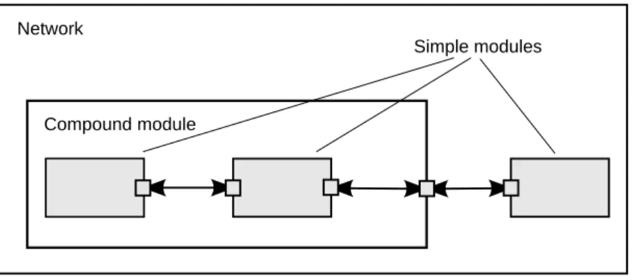
In Fig. 2.1, boxes represent simple modules (gray background) and compound modules. Arrows connecting small boxes represent connections and gates.
Network
Compound module
Simple modules
Figure 2.1: Simple and compound modules
Modules communicate with messages that may contain arbitrary data, in addition to usual attributes such as a timestamp. Simple modules typically send messages via gates, but it is also possible to send them directly to their destination modules. Gates are the input and output interfaces of modules: messages are sent through output gates and arrive through input gates. An input gate and output gate can be linked by a connection. Connections are created within a single level of module hierarchy; within a compound module, corresponding gates of two submodules, or a gate of one submodule and a gate of the compound module can be connected. Connections spanning hierarchy levels are not permitted, as they would hinder model reuse. Because of the hierarchical structure of the model, messages typically
travel through a chain of connections, starting and arriving in simple modules. Compound modules act like "cardboard boxes" in the model, transparently relaying messages between their inner realm and the outside world. Parameters such as propagation delay, data rate and bit error rate, can be assigned to connections. One can also define connection types with specific properties (termed channels) and reuse them in several places. Modules can have parameters. Parameters are used mainly to pass configuration data to simple modules, and to help define model topology. Parameters can take string, numeric, or boolean values. Because parameters are represented as objects in the program, parameters – in addition to holding constants – may transparently act as sources of random numbers, with the actual distributions provided with the model configuration. They may interactively prompt the user for the value, and they might also hold expressions referencing other parameters. Compound modules may pass parameters or expressions of parameters to their submodules.
OMNeT++ provides efficient tools for the user to describe the structure of the actual system. Some of the main features are the following:
• hierarchically nested modules
• modules are instances of module types
• modules communicate with messages through channels • flexible module parameters
• topology description language
2.1.1
Hierarchical Modules
An OMNeT++ model consists of hierarchically nested modules that communicate by passing messages to each other. OMNeT++ models are often referred to as networks. The top level module is thesystem module. The system module containssubmodulesthat can also contain submodules themselves (Fig. 2.1). The depth of module nesting is unlimited, allowing the user to reflect the logical structure of the actual system in the model structure.
Model structure is described in OMNeT++’s NED language.
Modules that contain submodules are termedcompound modules, as opposed tosimple mod-ules at the lowest level of the module hierarchy. Simple modules contain the algorithms of the model. The user implements the simple modules in C++, using the OMNeT++ simulation class library.
2.1.2
Module Types
Both simple and compound modules are instances of module types. In describing the model, the user defines module types; instances of these module types serve as components for more complex module types. Finally, the user creates the system module as an instance of a previously defined module type; all modules of the network are instantiated as submodules and sub-submodules of the system module.
When a module type is used as a building block, it makes no difference whether it is a simple or compound module. This allows the user to split a simple module into several simple modules embedded into a compound module, or vice versa, to aggregate the functionality of a compound module into a single simple module, without affecting existing users of the module type.
Module types can be stored in files separately from the place of their actual usage. This means that the user can group existing module types and create component libraries. This feature will be discussed later, in chapter 11.
2.1.3
Messages, Gates, Links
Modules communicate by exchangingmessages. In an actual simulation, messages can rep-resent frames or packets in a computer network, jobs or customers in a queuing network or other types of mobile entities. Messages can contain arbitrarily complex data structures. Simple modules can send messages either directly to their destination or along a predefined path, through gates and connections.
The “local simulation time” of a module advances when the module receives a message. The message can arrive from another module or from the same module (self-messagesare used to implement timers).
Gatesare the input and output interfaces of modules; messages are sent out through output gates and arrive through input gates.
Each connection (also called link) is created within a single level of the module hierarchy: within a compound module, one can connect the corresponding gates of two submodules, or a gate of one submodule and a gate of the compound module (Fig. 2.1).
Because of the hierarchical structure of the model, messages typically travel through a series of connections, starting and arriving in simple modules. Compound modules act like “card-board boxes” in the model, transparently relaying messages between their inner realm and the outside world.
2.1.4
Modeling of Packet Transmissions
To facilitate the modeling of communication networks, connections can be used to model physical links. Connections support the following parameters: data rate, propagation delay,
bit error rateandpacket error rate, and may be disabled. These parameters and the underlying algorithms are encapsulated into channel objects. The user can parameterize the channel types provided by OMNeT++, and also create new ones.
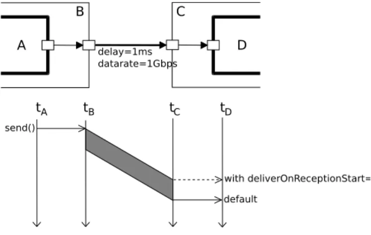
When data rates are in use, a packet object is by default delivered to the target module at the simulation time that corresponds to the end of the packet reception. Since this behavior is not suitable for the modeling of some protocols (e.g. half-duplex Ethernet), OMNeT++ provides the possibility for the target module to specify that it wants the packet object to be delivered to it when the packet reception starts.
2.1.5
Parameters
Modules can have parameters. Parameters can be assigned in either the NED files or the configuration fileomnetpp.ini.
Parameters can be used to customize simple module behavior, and to parameterize the model topology.
Parameters can take string, numeric or boolean values, or can contain XML data trees. Nu-meric values include expressions using other parameters and calling C functions, random variables from different distributions, and values input interactively by the user.
Numeric-valued parameters can be used to construct topologies in a flexible way. Within a compound module, parameters can define the number of submodules, number of gates, and the way the internal connections are made.
2.1.6
Topology Description Method
The user defines the structure of the model in NED language descriptions (Network Descrip-tion). The NED language will be discussed in detail in chapter 3.
2.2
Programming the Algorithms
The simple modules of a model contain algorithms as C++ functions. The full flexibility and power of the programming language can be used, supported by the OMNeT++ simulation class library. The simulation programmer can choose between event-driven and process-style description, and freely use object-oriented concepts (inheritance, polymorphism etc) and design patterns to extend the functionality of the simulator.
Simulation objects (messages, modules, queues etc.) are represented by C++ classes. They have been designed to work together efficiently, creating a powerful simulation programming framework. The following classes are part of the simulation class library:
• module, gate, parameter, channel • message, packet
• container classes (e.g. queue, array) • data collection classes
• statistic and distribution estimation classes (histograms, P2 algorithm for calculating
quantiles etc.)
• transient detection and result accuracy detection classes
The classes are also specially instrumented, allowing one to traverse objects of a running simulation and display information about them such as name, class name, state variables or contents. This feature makes it possible to create a simulation GUI where all internals of the simulation are visible.
2.3
Using OMNeT++
2.3.1
Building and Running Simulations
This section provides insights into working with OMNeT++ in practice. Issues such as model files and compiling and running simulations are discussed.
An OMNeT++ model consists of the following parts:
• NED language topology description(s) (.nedfiles) that describe the module structure with parameters, gates, etc. NED files can be written using any text editor, but the OMNeT++ IDE provides excellent support for two-way graphical and text editing.
• Message definitions (.msg files). You can define various message types and add data fields to them. OMNeT++ will translate message definitions into full-fledged C++ classes. • Simple module sources. They are C++ files, with.h/.ccsuffix.
The simulation system provides the following components:
• Simulation kernel. This contains the code that manages the simulation and the simula-tion class library. It is written in C++, compiled into a shared or static library.
• User interfaces. OMNeT++ user interfaces are used in simulation execution, to facilitate debugging, demonstration, or batch execution of simulations. They are written in C++, compiled into libraries.
Simulation programs are built from the above components. First,.msgfiles are translated into C++ code using theopp_msgc. program. Then all C++ sources are compiled and linked with the simulation kernel and a user interface library to form a simulation executable or shared library. NED files are loaded dynamically in their original text forms when the simulation program starts.
Running the Simulation and Analyzing the Results
The simulation may be compiled as a standalone program executable; thus it can be run on other machines without OMNeT++ being present, or it can be created as a shared library. In this case the OMNeT++ shared libraries must be present on that system. When the program is started, it first reads all NED files containing your model topology, then it reads a con-figuration file (usually calledomnetpp.ini). This file contains settings that control how the simulation is executed, values for model parameters, etc. The configuration file can also pre-scribe several simulation runs; in the simplest case, they will be executed by the simulation program one after another.
The output of the simulation is written into result files: output vector files, output scalar files, and possibly the user’s own output files. OMNeT++ contains an Integrated Development Environment (IDE) that provides rich environment for analyzing these files. Output files are line-oriented text files which makes it possible to process them with a variety of tools and programming languages as well, including Matlab, GNU R, Perl, Python, and spreadsheet programs.
User Interfaces
The primary purpose of user interfaces is to make the internals of the model visible to the user, to control simulation execution, and possibly allow the user to intervene by changing variables/objects inside the model. This is very important in the development/debugging phase of the simulation project. Equally important, a hands-on experience allows the user to get a feel of the model’s behavior. The graphical user interface can also be used to demonstrate a model’s operation.
The same simulation model can be executed with various user interfaces, with no change in the model files themselves. The user would typically test and debug the simulation with a powerful graphical user interface, and finally run it with a simple, fast user interface that supports batch execution.
Component Libraries
Module types can be stored in files separate from the place of their actual use, enabling the user to group existing module types and create component libraries.
Universal Standalone Simulation Programs
A simulation executable can store several independent models that use the same set of simple modules. The user can specify in the configuration file which model is to be run. This allows one to build one large executable that contains several simulation models, and distribute it as a standalone simulation tool. The flexibility of the topology description language also supports this approach.
2.3.2
What Is in the Distribution
If you installed the source distribution, the OMNeT++ directory on your system should con-tain the following subdirectories. (If you installed a precompiled distribution, some of the directories may be missing, or there might be additional directories, e.g. containing software bundled with OMNeT++.)
The simulation system itself:
omnetpp/ OMNeT++ root directory
bin/ OMNeT++ executables
include/ header files for simulation models
lib/ library files
images/ icons and backgrounds for network graphics
doc/ manuals, readme files, license, APIs, etc.
ide-customization-guide/ how to write new wizards for the IDE
ide-developersguide/ writing extensions for the IDE
manual/ manual in HTML
migration/ how to migrate your models from 3.x to 4.0 version
ned2/ DTD definition of the XML syntax for NED files
tictoc-tutorial/ introduction into using OMNeT++
api/ API reference in HTML
nedxml-api/ API reference for the NEDXML library
parsim-api/ API reference for the parallel simulation library
migrate/ tools to help model migration from 3.x to 4.0 version
src/ OMNeT++ sources
sim/ simulation kernel
parsim/ files for distributed execution
netbuilder/files for dynamically reading NED files
envir/ common code for user interfaces
cmdenv/ command-line user interface
tkenv/ Tcl/Tk-based user interface
nedxml/ NEDXML library, nedtool, opp_msgc
scave/ result analysis library
eventlog/ eventlog processing library
layout/ graph layouter for network graphics
common/ common library
test/ regression test suite
core/ tests for the simulation library
anim/ tests for graphics and animation
dist/ tests for the built-in distributions
makemake/ tests for opp_makemake ...
The Eclipse-based Simulation IDE is in theidedirectory.
ide/ Simulation IDE
features/ Eclipse feature definitions
plugins/ IDE plugins (extensions to the IDE can be dropped here) ...
The Windows version of OMNeT++ contains a redistribution of the MinGW gcc compiler, to-gether with a copy of MSYS that provides Unix tools commonly used in Makefiles. The MSYS directory also contains various 3rd party open-source libraries needed to compile and run OMNeT++.
tools/ Platform specific tools and compilers (e.g. MinGW/MSYS on Windows)
Sample simulations are in thesamplesdirectory.
samples/ directories for sample simulations
aloha/ models the Aloha protocol
cqn/ Closed Queueing Network ...
Thecontribdirectory contains material from the OMNeT++ community.
contrib/ directory for contributed material
akaroa/ Patch to compile akaroa on newer gcc systems
jsimplemodule/ Write simple modules in Java
topologyexport/ Export the topology of a model in runtime ...
Chapter 3
The NED Language
3.1
NED Overview
The user describes the structure of a simulation model in the NED language. NED stands for Network Description. NED lets the user declare simple modules, and connect and assemble them into compound modules. The user can label some compound modules asnetworks; that is, self-contained simulation models. Channels are another component type, whose instances can also be used in compound modules.
The NED language has several features which let it scale well to large projects:
Hierarchical. The traditional way to deal with complexity is by introducing hierarchies. In OMNeT++, any module which would be too complex as a single entity can be broken down into smaller modules, and used as a compound module.
Component-Based. Simple modules and compound modules are inherently reusable, which not only reduces code copying, but more importantly, allows component libraries (like the INET Framework, MiXiM, Castalia, etc.) to exist.
Interfaces. Module and channel interfaces can be used as a placeholder where normally a module or channel type would be used, and the concrete module or channel type is determined at network setup time by a parameter. Concrete module types have to “implement” the interface they can substitute. For example, given a compound module type namedMobileHostcontains amobilitysubmodule of the typeIMobility(where IMobilityis a module interface), the actual type ofmobilitymay be chosen from the module types that implemented IMobility (RandomWalkMobility, TurtleMobility, etc.)
Inheritance. Modules and channels can be subclassed. Derived modules and channels may add new parameters, gates, and (in the case of compound modules) new submodules and connections. They may set existing parameters to a specific value, and also set the gate size of a gate vector. This makes it possible, for example, to take aGenericTCPClientApp module and derive an FTPClientApp from it by setting certain parameters to a fixed value; or to derive a WebClientHost compound module from a BaseHost compound module by adding a WebClientApp submodule and connecting it to the inherited TCP submodule.
name clashes between different models. NEDPATH(similar to Java’sCLASSPATH) has also been introduced to make it easier to specify dependencies among simulation models. Inner types. Channel types and module types used locally by a compound module can be
defined within the compound module, in order to reduce namespace pollution.
Metadata annotations. It is possible to annotate module or channel types, parameters, gates and submodules by adding properties. Metadata are not used by the simulation kernel directly, but they can carry extra information for various tools, the runtime environment, or even for other modules in the model. For example, a module’s graphical representation (icon, etc) or the prompt string and measurement unit (milliwatt, etc) of a parameter are already specified as metadata annotations.
NOTE: The NED language has changed significantly in the 4.0 version. Inheritance, interfaces, packages, inner types, metadata annotations, inout gates were all added in the 4.0 release, together with many other features. Since the basic syntax has changed as well, old NED files need to be converted to the new syntax. There are automated tools for this purpose, so manual editing is only needed to take advantage of new NED features. The NED language has an equivalent tree representation which can be serialized to XML; that is, NED files can be converted to XML and back without loss of data, including comments. This lowers the barrier for programmatic manipulation of NED files; for example extracting information, refactoring and transforming NED, generating NED from information stored in other systems like SQL databases, and so on.
NOTE: This chapter is going to explain the NED language gradually, via examples. If you are looking for a more formal and concise treatment, see Appendix B.
3.2
NED Quickstart
In this section we introduce the NED language via a complete and reasonably real-life example: a communication network.
Our hypothetical network consists of nodes. On each node there is an application running which generates packets at random intervals. The nodes are routers themselves as well. We assume that the application uses datagram-based communication, so that we can leave out the transport layer from the model.
3.2.1
The Network
First we’ll define the network, then in the next sections we’ll continue to define the network nodes.
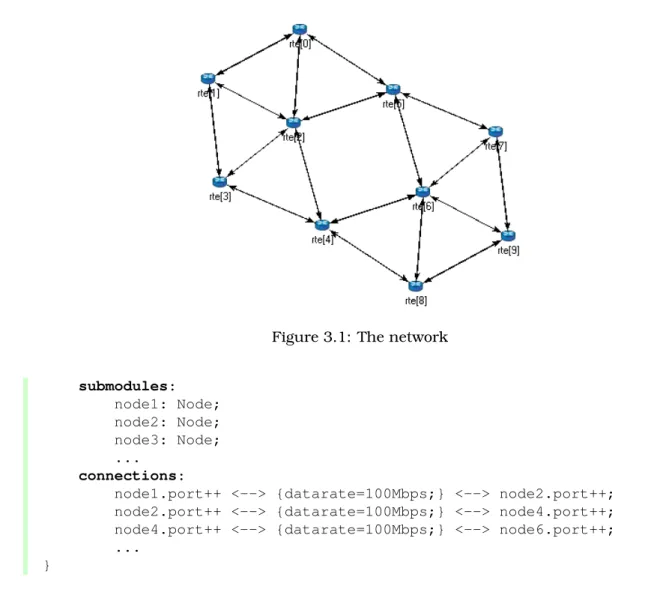
Let the network topology be as in Figure 3.1.
The corresponding NED description would look like this: //
// A network //
network Network {
Figure 3.1: The network submodules: node1: Node; node2: Node; node3: Node; ... connections:
node1.port++ <--> {datarate=100Mbps;} <--> node2.port++; node2.port++ <--> {datarate=100Mbps;} <--> node4.port++; node4.port++ <--> {datarate=100Mbps;} <--> node6.port++; ...
}
The above code defines a network type namedNetwork. Note that the NED language uses the familiar curly brace syntax, and “//” to denote comments.
NOTE: Comments in NED not only make the source code more readable, but in the OMNeT++ IDE they also are displayed at various places (tooltips, content assist, etc), and become part of the documentation extracted from the NED files. The NED documentation system, not unlikeJavaDocorDoxygen, will be described in Chapter 14.
The network contains several nodes, named node1, node2, etc. from the NED module type Node. We’ll defineNodein the next sections.
The second half of the declaration defines how the nodes are to be connected. The double arrow means bidirectional connection. The connection points of modules are called gates, and theport++notation adds a new gate to the port[] gate vector. Gates and connections will be covered in more detail in sections 3.7 and 3.9. Nodes are connected with a channel that has a data rate of 100Mbps.
NOTE: In many other systems, the equivalent of OMNeT++ gates are called ports. We have retained the term gate to reduce collisions with other uses of the otherwise over-loaded wordport: router port, TCP port, I/O port, etc.
The above code would be placed into a file named Net6.ned. It is a convention to put every NED definition into its own file and to name the file accordingly, but it is not mandatory to do so.
One can define any number of networks in the NED files, and for every simulation the user has to specify which network to set up. The usual way of specifying the network is to put the
networkoption into the configuration (by default theomnetpp.inifile): [General]
network = Network
3.2.2
Introducing a Channel
It is cumbersome to have to repeat the data rate for every connection. Luckily, NED provides a convenient solution: one can create a new channel type that encapsulates the data rate setting, and this channel type can be defined inside the network so that it does not litter the global namespace.
The improved network will look like this: // // A Network // network Network { types:
channel C extends ned.DatarateChannel { datarate = 100Mbps; } submodules: node1: Node; node2: Node; node3: Node; ... connections: node1.port++ <--> C <--> node2.port++; node2.port++ <--> C <--> node4.port++; node4.port++ <--> C <--> node6.port++; ... }
Later sections will cover the concepts used (inner types, channels, the DatarateChannel built-in type, inheritance) in detail.
3.2.3
The App, Routing, and Queue Simple Modules
Simple modules are the basic building blocks for other (compound) modules, denoted by the simple keyword. All active behavior in the model is encapsulated in simple modules. Behavior is defined with a C++ class; NED files only declare the externally visible interface of the module (gates, parameters).
In our example, we could defineNodeas a simple module. However, its functionality is quite complex (traffic generation, routing, etc), so it is better to implement it with several smaller
simple module types which we are going to assemble into a compound module. We’ll have one simple module for traffic generation (App), one for routing (Routing), and one for queueing up packets to be sent out (Queue). For brevity, we omit the bodies of the latter two in the code below. simple App { parameters: int destAddress; ... @display("i=block/browser"); gates: input in; output out; } simple Routing { ... } simple Queue { ... }
By convention, the above simple module declarations go into theApp.ned,Routing.nedand Queue.nedfiles.
NOTE: Note that module type names (App,Routing,Queue) begin with a capital letter, and parameter and gate names begin with lowercase – this is the recommended naming convention. Capitalization matters because the language is case sensitive.
Let us look at the first simple module type declaration. Apphas a parameter called destAd-dress(others have been omitted for now), and two gates namedoutandinfor sending and receiving application packets.
The argument of @display() is called a display string, and it defines the rendering of the module in graphical environments;"i=..."defines the default icon.
Generally,@-words like@displayare calledpropertiesin NED, and they are used to annotate various objects with metadata. Properties can be attached to files, modules, parameters, gates, connections, and other objects, and parameter values have a very flexible syntax.
3.2.4
The Node Compound Module
Now we can assembleApp,RoutingandQueueinto the compound moduleNode. A compound module can be thought of as a “cardboard box” that groups other modules into a larger unit, which can further be used as a building block for other modules; networks are also a kind of compound module.
module Node {
Figure 3.2: The Node compound module parameters: int address; @display("i=misc/node_vs,gold"); gates: inout port[]; submodules: app: App; routing: Routing;
queue[sizeof(port)]: Queue;
connections:
routing.localOut --> app.in; routing.localIn <-- app.out;
for i=0..sizeof(port)-1 {
routing.out[i] --> queue[i].in; routing.in[i] <-- queue[i].out; queue[i].line <--> port[i]; }
}
Compound modules, like simple modules, may have parameters and gates. OurNodemodule contains anaddressparameter, plus agate vector of unspecified size, namedport. The ac-tual gate vector size will be determined implicitly by the number of neighbours when we create a network from nodes of this type. The type of port[]is inout, which allows bidirectional connections.
The modules that make up the compound module are listed under submodules. Our Node compound module type has an app and a routing submodule, plus a queue[] submodule vector that contains one Queue module for each port, as specified by [sizeof(port)]. (It is legal to refer to [sizeof(port)]because the network is built in top-down order, and the node is already created and connected at network level when its submodule structure is built out.)
In theconnections section, the submodules are connected to each other and to the parent
module. Single arrows are used to connect input and output gates, and double arrows connect inout gates, and aforloop is utilized to connect theroutingmodule to eachqueuemodule, and to connect the outgoing/incoming link (line gate) of each queue to the corresponding port of the enclosing module.
3.2.5
Putting It Together
We have created the NED definitions for this example, but how are they used by OMNeT++? When the simulation program is started, it loads the NED files. The program should already contain the C++ classes that implement the needed simple modules,App,RoutingandQueue; their C++ code is either part of the executable or is loaded from a shared library. The simu-lation program also loads the configuration (omnetpp.ini), and determines from it that the simulation model to be run is the Network network. Then the network is instantiated for simulation.
The simulation model is built in a top-down preorder fashion. This means that starting from an empty system module, all submodules are created, their parameters and gate vector sizes are assigned, and they are fully connected before the submodule internals are built.
* * *
In the following sections we’ll go through the elements of the NED language and look at them in more detail.
3.3
Simple Modules
Simple modules are the active components in the model. Simple modules are defined with the
simplekeyword.
An example simple module:
simple Queue { parameters: int capacity; @display("i=block/queue"); gates: input in; output out; }
Both theparametersandgatessections are optional, that is, they can be left out if there is no parameter or gate. In addition, theparameterskeyword itself is optional too; it can be left out even if there are parameters or properties.
Note that the NED definition doesn’t contain any code to define the operation of the module: that part is expressed in C++. By default, OMNeT++ looks for C++ classes of the same name as the NED type (so here,Queue).
One can explicitly specify the C++ class with the @classproperty. Classes with namespace qualifiers are also accepted, as shown in the following example that uses the mylib::Queue class:
simple Queue {
parameters:
@class(mylib::Queue); @display("i=block/queue"); gates: input in; output out; }
If you have several modules that are all in a common namespace, then a better alterna-tive to @classis the@namespaceproperty. The C++ namespace given with @namespacewill be prepended to the normal class name. In the following example, the C++ classes will be mylib::App,mylib::Routerandmylib::Queue:
@namespace(mylib); simple App { ... } simple Router { ... } simple Queue { ... }
As you’ve seen, @namespace can be specified at the file level. Moreover, when placed in a file called package.ned, the namespace will apply to all files in the same directory and all directories below.
The implementation C++ classes need to be subclassed from thecSimpleModulelibrary class; chapter 4 of this manual describes in detail how to write them.
Simple modules can be extended (or specialized) via subclassing. The motivation for subclass-ing can be to set some open parameters or gate sizes to a fixed value (see 3.6 and 3.7), or to replace the C++ class with a different one. Now, by default, the derived NED module type will
inherit the C++ class from its base, so it is important to remember that you need to write out @classif you want it to use the new class.
The following example shows how to specialize a module by setting a parameter to a fixed value (and leaving the C++ class unchanged):
simple Queue {
int capacity; ...
}
simple BoundedQueue extends Queue {
capacity = 10; }
In the next example, the author wrote a PriorityQueue C++ class, and wants to have a corresponding NED type, derived fromQueue. However, it does not work as expected:
simple PriorityQueue extends Queue // wrong! still uses the Queue C++ class {
}
The correct solution is to add a@classproperty to override the inherited C++ class:
simple PriorityQueue extends Queue {
@class(PriorityQueue); }
Inheritance in general will be discussed in section 3.13.
3.4
Compound Modules
A compound module groups other modules into a larger unit. A compound module may have gates and parameters like a simple module, but no active behavior is associated with it.1
NOTE: When there is a temptation to add code to a compound module, then encapsulate the code into a simple module, and add it as a submodule.
A compound module declaration may contain several sections, all of them optional:
module Host { types: ... parameters: ... gates: ... submodules: ... connections: ... }
Modules contained in a compound module are called submodules, and they are listed in the submodulessection. One can create arrays of submodules (i.e. submodule vectors), and the submodule type may come from a parameter.
Connections are listed under the connections section of the declaration. One can create connections using simple programming constructs (loop, conditional). Connection behaviour can be defined by associating a channel with the connection; the channel type may also come from a parameter.
Module and channel types only used locally can be defined in the types section as inner types, so that they do not pollute the namespace.
Compound modules may be extended via subclassing. Inheritance may add new submod-ules and new connections as well, not only parameters and gates. Also, one may refer to
1Although the C++ class for a compound module can be overridden with the@classproperty, this is a feature that
inherited submodules, to inherited types etc. What is not possible is to "de-inherit" or modify submodules or connections.
In the following example, we show how to assemble common protocols into a "stub" for wireless hosts, and add user agents via subclassing.2
module WirelessHostBase { gates: input radioIn; submodules: tcp: TCP; ip: IP; wlan: Ieee80211; connections: tcp.ipOut --> ip.tcpIn; tcp.ipIn <-- ip.tcpOut; ip.nicOut++ --> wlan.ipIn; ip.nicIn++ <-- wlan.ipOut; wlan.radioIn <-- radioIn; }
module WirelessHost extends WirelessHostBase { submodules: webAgent: WebAgent; connections: webAgent.tcpOut --> tcp.appIn++; webAgent.tcpIn <-- tcp.appOut++; }
TheWirelessHostcompound module can further be extended, for example with an Ethernet port:
module DesktopHost extends WirelessHost { gates: inout ethg; submodules: eth: EthernetNic; connections: ip.nicOut++ --> eth.ipIn; ip.nicIn++ <-- eth.ipOut; eth.phy <--> ethg; }
3.5
Channels
Channels encapsulate parameters and behaviour associated with connections. Channels are like simple modules, in the sense that there are C++ classes behind them. The rules for
2Module types, gate names, etc. used in the example are fictional, not based on an actual OMNeT++-based model
finding the C++ class for a NED channel type is the same as with simple modules: the default class name is the NED type name unless there is a @class property (@namespace is also recognized), and the C++ class is inherited when the channel is subclassed.
Thus, the following channel type would expect aCustomChannelC++ class to be present:
channel CustomChannel // requires a CustomChannel C++ class {
}
The practical difference compared to modules is that you rarely need to write you own channel C++ class because there are predefined channel types that you can subclass from, inherit-ing their C++ code. The predefined types are: ned.IdealChannel, ned.DelayChannel and ned.DatarateChannel. (“ned” is the package name; you can get rid of it if you import the types with the import ned.* or similar directive. Packages and imports are described in section 3.14.)
IdealChannelhas no parameters, and lets through all messages without delay or any side effect. A connection without a channel object and a connection with anIdealChannelbehave in the same way. Still, IdealChannel has its uses, for example when a channel object is required so that it can carry a new property or parameter that is going to be read by other parts of the simulation model.
DelayChannelhas two parameters:
• delay is a double parameter which represents the propagation delay of the message. Values need to be specified together with a time unit (s,ms,us, etc.)
• disabledis a boolean parameter that defaults tofalse; when set totrue, the channel object will drop all messages.
DatarateChannelhas a few additional parameters compared toDelayChannel:
• datarate is a double parameter that represents the data rate of the channel. Values need to be specified in bits per second or its multiples as unit (bps,kbps, Mbps, Gbps, etc.) Zero is treated specially and results in zero transmission duration, i.e. it stands for infinite bandwidth. Zero is also the default. Data rate is used for calculating the transmission duration of packets.
• ber and per stand for Bit Error Rate and Packet Error Rate, and allow basic error modelling. They expect a double in the[0,1]range. When the channel decides (based on random numbers) that an error occurred during transmission of a packet, it sets an error flag in the packet object. The receiver module is expected to check the flag, and discard the packet as corrupted if it is set. The defaultberandperare zero.
NOTE: There is no channel parameter that specifies whether the channel delivers the message object to the destination module at the end or at the start of the reception; that is decided by the C++ code of the target simple module. See the setDeliverOnReception-Start()method ofcGate.
The following example shows how to create a new channel type by specializing Datarate-Channel:
channel Ethernet100 extends ned.DatarateChannel {
datarate = 100Mbps; delay = 100us; ber = 1e-10; }
NOTE: The three built-in channel types are also used for connections where the channel type is not explicitly specified.
You may add parameters and properties to channels via subclassing, and may modify existing ones. In the following example, we introduce distance-based calculation of the propagation delay:
channel DatarateChannel2 extends ned.DatarateChannel {
double distance @unit(m);
delay = this.distance / 200000km * 1s;
}
Parameters are primarily useful as input to the underlying C++ class, but even if you reuse the underlying C++ class of built-in channel types, they may be read and used by other parts of the model. For example, adding acostparameter (or @costproperty) may be observed by the routing algorithm and used for routing decisions. The following example shows a cost parameter, and annotation using a property (@backbone).
channel Backbone extends ned.DatarateChannel {
@backbone;
double cost = default(1); }
3.6
Parameters
Parameters are variables that belong to a module. Parameters can be used in building the topology (number of nodes, etc), and to supply input to C++ code that implements simple modules and channels.
Parameters can be of type double, int, bool, string and xml; they can also be declared
volatile. For the numeric types, a unit of measurement can also be specified (@unit prop-erty), to increase type safety.
Parameters can get their value from NED files or from the configuration (omnetpp.ini). A default value can also be given (default(...)), which is used if the parameter is not assigned otherwise.
The following example shows a simple module that has five parameters, three of which have default values:
simple App {
parameters:
string protocol; // protocol to use: "UDP" / "IP" / "ICMP" / ...
int destAddress; // destination address
// time between generating packets
volatile int packetLength @unit(byte) = default(100B); // length of one packet
volatile int timeToLive = default(32);
// maximum number of network hops to survive
gates:
input in;
output out; }
Assigning a Value
Parameters may get their values in several ways: from NED code, from the configuration (omnetpp.ini), or even, interactively from the user. NED lets you assign parameters at several places: in subclasses via inheritance; in submodule and connection definitions where the NED type is instantiated; and in networks and compound modules that directly or indirectly contain the corresponding submodule or connection.
For instance, one could specialize the aboveAppmodule type via inheritance with the following definition:
simple PingApp extends App {
parameters:
protocol = "ICMP/ECHO" sendInterval = default(1s); packetLength = default(64byte); }
This definition sets the protocol parameter to a fixed value ("ICMP/ECHO"), and changes the default values of the sendInterval and packetLength parameters. protocol is now locked down inPingApp, its value cannot be modified via further subclassing or other ways. sendInterval and packetLength are still unassigned here, only their default values have been overwritten.
Now, let us see the definition of aHostcompound module that usesPingAppas submodule:
module Host {
submodules:
ping : PingApp {
packetLength = 128B; // always ping with 128-byte packets }
... }
This definition sets the packetLengthparameter to a fixed value. It is now hardcoded that Hosts send 128-byte ping packets; this setting cannot be changed from NED or the configu-ration.
It is not only possible to set a parameter from the compound module that contains the sub-module, but also from modules higher up in the module tree. If you had a network that employed severalHostmodules, it could be defined like this:
{ submodules: host[100]: Host { ping.timeToLive = default(3); ping.destAddress = default(0); } ... }
Parameter assignment can also be placed into theparametersblock of the parent compound module, which provides additional flexibility. The following definition sets up the hosts so that half of them pings host #50, and the other half pings host #0:
network Network { parameters: host[*].ping.timeToLive = default(3); host[0..49].ping.destAddress = default(50); host[50..].ping.destAddress = default(0); submodules: host[100]: Host; ... }
Note the use of asterisk to match any index, and ‘..’ to match index ranges.
If you had a number of individual hosts instead of a submodule vector, the network definition could look like this:
network Network { parameters: host*.ping.timeToLive = default(3); host{0..49}.ping.destAddress = default(50); host{50..}.ping.destAddress = default(0); submodules: host0: Host; host1: Host; host2: Host; ... host99: Host; }
An asterisk matches any substring not containing a dot, and a ‘..’ within a pair of curly braces matches a natural number embedded in a string.
In most assigments we have seen above, the left hand side of the equal sign contained a dot and often a wildcard as well (asterisk or numeric range); we call these assignments pattern assignmentsordeep assignments.
There is one more wildcard that can be used in pattern assignments, and this is the double asterisk; it matches any sequence of characters including dots, so it can match multiple path elements. An example:
network Network { parameters: **.timeToLive = default(3); **.destAddress = default(0); submodules: host0: Host; host1: Host; ... }
Note that some assignments in the above examples changed default values, while others set parameters to fixed values. Parameters that received no fixed value in the NED files can be assigned from the configuration (omnetpp.ini).
IMPORTANT: A non-default value assigned from NED cannot be overwritten later in NED or from ini files; it becomes “hardcoded” as far as ini files and NED usage are concerned. In contrast, default values are possible to overwrite.
A parameter can be assigned in the configuration using a similar syntax as NED pattern assignments (actually, it would be more historically accurate to say it the other way round, that NED pattern assignments use a similar syntax to ini files):
Network.host[*].ping.sendInterval = 500ms # for the host[100] example
Network.host*.ping.sendInterval = 500ms # for the host0,host1,... example **.sendInterval = 500ms
One often uses the double asterisk to save typing. You can write **.ping.sendInterval = 500ms
Or if you are sure that you don’t accidentally assign some other sendIntervalparameter, you can just write
**.sendInterval = 500ms
Parameter assignments in the configuration are described in section 10.3.
One can also write expressions, including stochastic expressions, in NED files and in ini files as well. For example, here’s how you can add jitter to the sending of ping packets:
**.sendInterval = 1s + normal(0s, 0.001s) # or just: normal(1s, 0.001s) If there is no assignment for a parameter in NED or in the ini file, the default value (given with=default(...) in NED) will be applied implicitly. If there is no default value, the user will be asked, provided the simulation program is allowed to do that; otherwise there will be an error. (Interactive mode is typically disabled for batch executions where it would do more harm than good.)
It is also possible to explicitly apply the default (this can sometimes be useful): **.sendInterval = default
Finally, one can explicitly ask the simulator to prompt the user interactively for the value (again, provided that interactivity is enabled; otherwise this will result in an error):
![Figure 3.2: The Node compound module parameters: int address; @display("i=misc/node_vs,gold"); gates: inout port[]; submodules: app: App; routing: Routing; queue[sizeof(port)]: Queue; connections: routing.localOut --> app.in; routing.localIn <](https://thumb-us.123doks.com/thumbv2/123dok_us/1814104.2761332/34.918.358.594.159.385/figure-compound-parameters-address-submodules-routing-connections-localout.webp)