Using Model Driven Architecture to Develop
Multi-Agent Systems
Mohamed Elammari and Zeinab Issa
Faculty of Information Technology, University of Benghazi, Libya
Abstract: In recent years, Multi-Agent Systems (MAS) had started gaining widespread acceptance in the field of information technology. This prompted many researchers to attempt to find ways to facilitate their development process, which typically includes building different models. The transformation of system specifications into models and their subsequent translation into code is often performed by relying on unstandardized methods, hindering adaptation to rapid changes in technology. Furhtermore, there is a big gap between the analysis, the design and the implementation in the methodologies of multi-agent systems development. On the other hand, we have seen that the top-down Model Driven Architecture (MDA) approach can be used to provide an efficient way to write specifications, develop applications and separation of business functions and application from the technical platform to be used. In this work, we propose using the MDA architecture for developing MAS. We demonstrate several different approaches, resulting in a variety of methods for developing MAS. This, in turn, increases the flexibility and ease of the development of MAS, and avoids any previously imposed restrictions.
Keywords:MDA, MAS, web ontology language, XMI.
Received May 4, 2011; accepted July 28, 2011; published online August 5, 2012
1.
Introduction
The importance, the prevalence, the difficulty of management and control of software development processes are the key factors that lead to the need for providing development mechanisms that would shorten project life cycles and make the software components more reusable. This became particularly important with the emergence of new technologies such as agents.
Due to the widespread usage of software in many fields, a software agent should be able to provide designers with a way to structure the applications into the components capable of independently responding to changes in the environment.
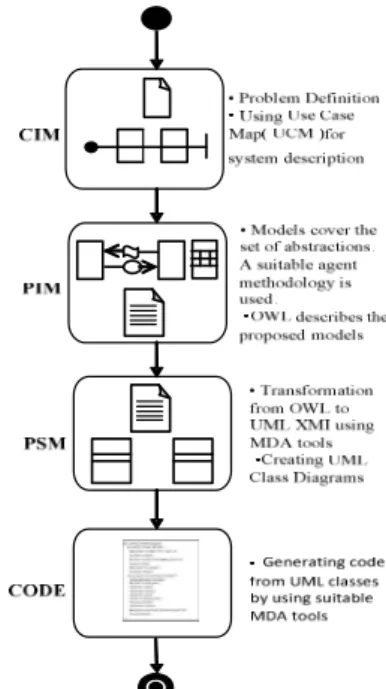
In this paper, we propose using Model Driven Architecture (MDA) [10] for the development of Multi-Agent Systems (MAS). It has been issued by the Object Management Group (OMG) and defined as a way to organize and support project management and architectural models by using tools that define the models and make their communication easy [4]. MDA is comprised of four stages and set of transformations from one stage to another. For example, the Computational Independent Model (CIM) stage does not show the system structure details, and is, thus, sometimes referred to as domain model. The Platform Independent Model (PIM) stage offers a degree of platform independence, making it suitable for a wide range of platforms. The next stage is the Platform Specific Model (PSM) stage; it integrates existing specifications in the PIM with the details that define
how the system uses a particular type of platform. The final stage generates the application code. MDA
objectives are portability, interoperability and
reusability [10]. This paper focuses on using MDA to develop MAS.
The paper is organized as follows. Section 2 describes some related work, and the use of MDA to develop MAS is presented in section 3. Finally, conclusions and future work are given in section 4.
2.
Related Work
Brandão et al. [3] were the first to use MDA to the
development of MAS. In their work, the authors suggested using Web Ontology Language (OWL) in the CIM stage, the TXL programming language in the transition from this stage to PIM stage, followed by the use of MAS-ML modeling language. Finally, they advocate for relying on MAS-ML grammar in the transition to XMI and then using JADE platform for the transition to UML models, considered a PSM stage.
De-Maria et al. [6] subsequently used MDA for the
development of MAS, which can be considered as an extension of their previous work. They started the PIM stage by using the MAS-ML modeling language, and translated these models into the MAS-ML XMI, followed by translation to the UML XMI. These two steps were based on ASF framework. In the final stage, the authors generated Java code from UML models by using the MDA tools.
Using MDA, Amor et al. [1] bridged the gap
oriented systems. They demonstrated how the MDA could be used to derive practical applications of Agents from Agent oriented design. The authors proposed an independent form, derived from any selected methodologies and agent platforms, in addition to the partial automatic support to the derivation of the applications of MAS. Their major contributions were in the definition of a common, agent-neutral model that applies to all the concepts required by the FIPA-compliant agent platform. They also pioneered the use
of MDA mechanisms for the definition of
transformations between design models produced by the agent oriented methodologies and Malaca model. They implemented some aspects of their expertise in the derivation and application of these conversions to Tropos methodology.
In a similar work, Nikraz et al. [11] developed
methodology for developing MAS using JADE platform, which primarily focuses on analysis and design phases. They used FIPA-compliant JADE Platform in the design phase.
DeLoach and Wood [7] proposed developing MAS using Multiagent Systems Engineering (MaSE) methodology and agent tool. The methodology focused on capturing goals and combing them to form roles, including tasks that specify how the roles satisfy their goals. In the design phase, the roles are combined to define agent classes, whilst tasks are used to identify conversations between the classes. The authors used object-oriented principles as a basis for their methodology, and relied on UML deployment diagram in run-time system structure. MaSE and agent tool has been designed to develop five to ten small to medium
sized multi-agent systems. Dikenelli et al. [8]
developed MAS by using framework called
SEAGENT, which works in the semantic web environment.
Xuet et al. [12] proposed role-based methodology
for multi-agent systems to separate the conceptual roles and their practical instances. In this work, role organization is defined for modeling roles as well as their relationships. The inheritance relationship is explicitly defined using Object-Z formalization. Role space is then defined as a set of role instances (created at runtime), and serves to provide services for software agent. Thus, agents can dynamically take or release role instances from a role space.
3.
The Use of MDA to Develop MAS
Our proposal focuses on applying the top-down MDA architecture to build MAS and-based on its characteristics-define the MDA stages, and the transitions between them. In this work, we focus on the representation of CIMs, their transformation into PIMs, and the definition of MAS PIMs. We also present transformations from these models into PSMs, their specification and subsequent transformations into code.
Figure 1 illustrates the conceptual overview of the proposed solution.
Figure 1. Conceptual overview of the proposed solution.
3.1.Computational Independent Models
Definition of CIMs requires the following steps: problem definition and description of system requirements, achieved by defining the functions the system performs (i.e., what, rather than how). The use case diagram is proposed to clarify the main system functions, whereas the scenarios will be described by using Use Case Map (UCM).
“The UCM notation aims to link behavior and structure in an explicit and visual way.” It provides a powerful visual notation for a review and the ability to efficiently design of complex systems. Furthermore, this approach allows for detailed critique of the design [2, 9]. Figure 2 illustrates the conceptual overview of the CIM stage.
Figure 2. Conceptual overview of the CIM stage.
The UCM illustrated in Figure 3 describes part of the system's scenarios of an example system referred to as EU-Rent. The first step in the UCM is the Cus_Agent request for a car reservation. The Rent_Agent performs a search, and, unless the customer is found in the
company’s black list, the customer is prompted to specify the car type, model and duration of the reservation. In the next step, the Rent_Agent checks car on site availability, or requests an order from another branch, and subsequently issues the reservation document.
Figure 3. UCM (Car Reservation).
3.2.Transforming CIMs into PIMs
The first transformation from CIM to PIM will be done manually. Each path defined in UCM represents agents' goals, where each precondition and post-condition represents agents' beliefs, while the responsibilities represent agents' tasks. Figure 4
illustrates the conceptual overview of the
transformation operation from CIMs into PIMs.
Figure 4. Conceptual overview of the transformation from CIMs into PIMs.
3.3.Platform Independent Models
In this stage, the MAS structural aspects (the abstractions, their properties and their relationships) and the MAS dynamic aspects (interactions between the abstractions and their internal executions) are modeled. The implementation of the proposed models is not restricted to a specific platform. Furthermore, some models are modified models available within the HLIM methodology.
3.3.1.Structure Model
The term organization is used to represent partitions and groups of entities, such as departments, communities and societies [6]. Similar to agents, organizations are autonomous, interactive and adaptive entities that have goals, beliefs, plans and actions.
Agents, organizations and objects comprise
environments, where they are executed and interact
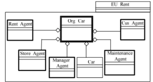
with each other. The aggregation relationship is used to represent the relationship between entities and the environments that they inhabit. An object is an interactive entity, rather than an autonomous one. Thus, the autonomy property is one of the most important differences between an agent and an object, given that objects are reactive and passive entities. The organization diagram illustrated in the Figure 5 depicts models of the above example of EU-Rent Car Rentals, defined in the previous stage. The roles of Agents and objects defined by the organization are represented by the model.
The Org_Car defines roles played by the Cus_Agent agent (the customers in the systems) and Rent_Agent agent (the employee who is responsible for the rental
procedures in the system). Furthermore, the
organization also defines the negotiations among agents about the object (car).
Figure 5. Conceptual overview of the structural model. In order to exemplify some properties of Cus_Agent, they are defined in an entity. The properties of an agent are defined as goals, beliefs, plans, and tasks and are detailed in Table 1 below.
Table 1. Cus_Agent properties.
Agent name: Cus_Agent
Goal Plan Tasks Beliefs
car rent use internet
Task name Task
description •Car information •Credit card validity •Driver license validity •Sending order to rent a car •Sending personal data •Sending driver’s additional data •Determine payment method •Sending insurance details •Signing rent agreement Finishing the car return procedures Use credit card •Sending credit card data •Rent value •Branch information •Delivering insurance Use bank data •Sending bank account data •Delivering insurance Extending Rent Order extended rental •Sending request to extend rental period •Period of rent Agent Beliefs 1.Car information 2. Branch information 3. Credit card validity 4. Driver license validity 5. Rent value 6. Period of rent
3.3.2.Dynamic Model
The purpose of the dynamic model is to represent the interactions among agents, their policies and commitments to each other. It comprises both the commitment and the conversation model. The Commitment model illustrates the commitments between agents and as shown in Table 2 below is comprised of four parts: the committed participants, authorizations that specify the services that the agents are committed to provide to each other, policies that specify the service quality and capacity, and relevant information regarding their importance to an application as well as their usage policy [9]. Table 2 describes commitments between Cus_Agent and Rent_Agent from the previous example.
Table 2. Example of a commitment model.
Cus_Agent CONTRACT Rent_Agent
Authorizations request of car rent()
request of extending rent()
determine period of rent() issuing scrip of receiving() determine the end of rental period () extending rent()
Obligations Provide: determine payment
method()
Provide: sending insurance details()
Provide: issuing receiving model ( ) when receiving car
Provide: insurance returning when receiving rent value
Policies •Determine car set and car model
when making rent order.
•Check of car procedures before car rent •Check car date for maintenance before
renting car
•Informing Police and Insurance Company on failure to return the car after three days Beliefs
•Car information •Branch information •Credit card validity •Rent value
•Customer information •Driver license validity •Car condition
3.3.3. Conversations Between Cus_Agent and Rent_Agent
The conversation model illustrates the messages exchanged between agents, depicted by UML sequence diagram (see Cus_Agent and Rent_Agent in Figure 6).
Figure 6. Conversation model.
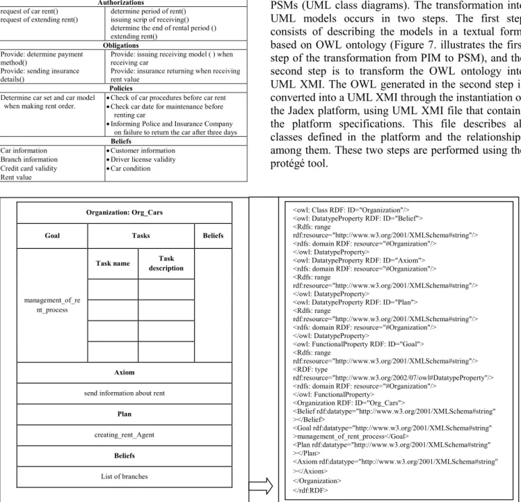
3.4.Transforming PIMs into PSMs
After PIMs modeling, the models are transformed into PSMs (UML class diagrams). The transformation into UML models occurs in two steps. The first step consists of describing the models in a textual form, based on OWL ontology (Figure 7. illustrates the first step of the transformation from PIM to PSM), and the second step is to transform the OWL ontology into UML XMI. The OWL generated in the second step is converted into a UML XMI through the instantiation of the Jadex platform, using UML XMI file that contains the platform specifications. This file describes all classes defined in the platform and the relationships
among them. These two steps are performed using the
protégé tool.
Figure 7. Transformation from PIM into OWL.
Organization: Org_Cars
Goal Tasks Beliefs
management_of_re nt_process
Task name Task
description
Axiom
send information about rent
Plan
creating_rent_Agent
Beliefs
List of branches
<owl: Class RDF: ID="Organization"/> <owl: DatatypeProperty RDF: ID="Belief"> <Rdfs: range
rdf:resource="http://www.w3.org/2001/XMLSchema#string"/> <rdfs: domain RDF: resource="#Organization"/>
</owl: DatatypeProperty>
<owl: DatatypeProperty RDF: ID="Axiom"> <rdfs: domain RDF: resource="#Organization"/> <Rdfs: range
rdf:resource="http://www.w3.org/2001/XMLSchema#string"/> </owl: DatatypeProperty>
<owl: DatatypeProperty RDF: ID="Plan"> <Rdfs: range
rdf:resource="http://www.w3.org/2001/XMLSchema#string"/> <rdfs: domain RDF: resource="#Organization"/>
</owl: DatatypeProperty>
<owl: FunctionalProperty RDF: ID="Goal"> <Rdfs: range rdf:resource="http://www.w3.org/2001/XMLSchema#string"/> <RDF: type rdf:resource="http://www.w3.org/2002/07/owl#DatatypeProperty"/> <rdfs: domain RDF: resource="#Organization"/> </owl: FunctionalProperty> <Organization RDF: ID="Org_Cars"> <Belief rdf:datatype="http://www.w3.org/2001/XMLSchema#string" ></Belief> <Goal rdf:datatype="http://www.w3.org/2001/XMLSchema#string" >management_of_rent_process</Goal> <Plan rdf:datatype="http://www.w3.org/2001/XMLSchema#string" ></Plan> <Axiom rdf:datatype="http://www.w3.org/2001/XMLSchema#string" ></Axiom> </Organization> </rdf:RDF>
3.5.Platform Specific Models
The generated UML XMI represents the application PSM. By using of the Poseidon tool, the UML XMI is imported to generate the application's UML model. This is a class diagram that contains the Jadex platform classes and the classes related to the application that instantiates the platform. Figure 8 illustrates an example of the PSM stage.
Figure 8. An example of the PSM stage.
All entities, properties and relationships of our application are modeled using the structural diagrams
(the abstractions, their properties and their
relationships) during the PIM stage, whereas, in the
PSM stage, these models are represented by UML class diagram.
3.6.Transforming PSMs into Code
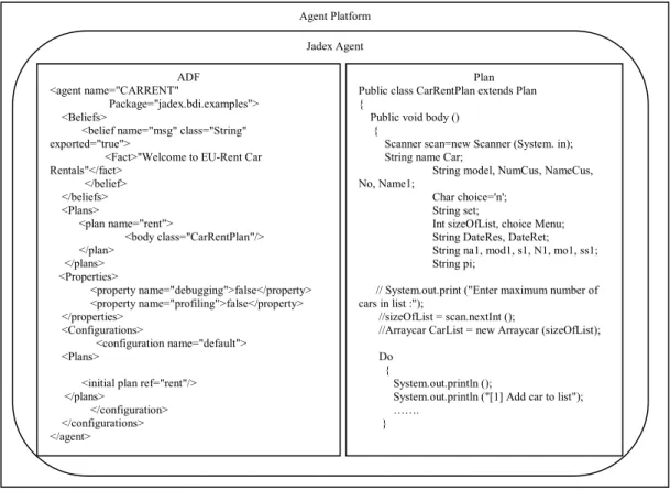
According to the MDA top-down approach, this stage corresponds to the transformation of PSMs into application code. Using the Poseidon tool, the UML models that represent the MAS are automatically transformed into object-oriented code. This process corresponds to the last stage of the MDA approach that transforms PSMs into code. However, it is worth noting that the generated code requires some modifications in order to be run on the Jadex platform, as it contains only the main classes and their methods. Furthermore, the methods contain only basic instructions, which are insufficient for the code execution as shown in Figure 9.
Figure 9. An example of the Jadex platform.
4.
Conclusions
In this paper, the MAS development process has been presented, as an effective and efficient approach to modeling and implementing MAS using MDA. The proposed process consists of four stages.
In the first stage, the approach based on UML uses case diagram to describe the main system functions,
and describes the system's scenarios by using UCM. UCM provides a powerful visual notation for a review and ability efficiently depict complex system designs. In addition, it enables detailed critique of that design, which allows for further modifications, if necessary.
In the second stage, the UCMs are transformed manually into PIM models by describing the system at an Agent oriented level, whereby agent goals are
Agent Platform ADF <agent name="CARRENT" Package="jadex.bdi.examples"> <Beliefs>
<belief name="msg" class="String" exported="true">
<Fact>"Welcome to EU-Rent Car Rentals"</fact> </belief> </beliefs> <Plans> <plan name="rent"> <body class="CarRentPlan"/> </plan> </plans> <Properties> <property name="debugging">false</property> <property name="profiling">false</property> </properties> <Configurations> <configuration name="default"> <Plans>
<initial plan ref="rent"/> </plans>
</configuration> </configurations> </agent>
Plan Public class CarRentPlan extends Plan {
Public void body () {
Scanner scan=new Scanner (System. in); String name Car;
String model, NumCus, NameCus, No, Name1;
Char choice='n'; String set;
Int sizeOfList, choice Menu; String DateRes, DateRet; String na1, mod1, s1, N1, mo1, ss1; String pi;
// System.out.print ("Enter maximum number of cars in list :");
//sizeOfList = scan.nextInt ();
//Arraycar CarList = new Arraycar (sizeOfList);
Do {
System.out.println ();
System.out.println ("[1] Add car to list"); …….
} JadexAgent
represented by paths, responsibilities correspond to agent's tasks, and preconditions and post-conditions relate to agent's beliefs.
In the third stage, the PIM models are transformed into UML models according to the Jadex platform, by describing the system as an Object oriented level. Here, the automatic transformation was performed by using the protégé tool to transfer the models of PIM into OWL, followed by the transfer of OWL into UML XMI. Finally, the UML XMI is transferred into UML class diagram by using the Poseidon tool.
In the fourth and final stage, the UML models are automatically transformed into code using the Poseidon tool.
The proposed MAS development process has three main characteristics that can be summarized as follows:
1. Using UCM in the CIM stage: UCM is a visual notation that helps in understanding the system requirements in the form of high-level system overview. This approach allows the user to describe the system without focusing on its detailed structure.
2. Portability and reusability: Separating the implementation details from design models is the fundamental prerequisite of any system. In the present work, the models used to define the design models are portable; consequently, they can be used by different implementing platforms. This is due to the fact that MAS can be described without including the implementation details. Thus, these models can be reused by several developers to implement the system on different platforms. 3. Interoperability: Interoperability between PIM and
PSM models is achieved by the use of OWL to describe models created during the development process. Furthermore, PIM models and UML models are interoperable due to the use of OWL and UML XMI.
4. Low coupling: Owing to the intrinsic characteristics of MDA, conceptual models (PIM) and computation models (PSM) are low coupling. In the present work, PIM models do not include details related to a specific platform, as they are present in PSMs only (UML models).
5.
Future Work
• More empirical applications are needed for
thorough assessment and evaluation of the proposed approach. Practical evaluations allow for immediate identification of issues that can be taken into consideration when improving the effectiveness of the proposed approach.
• The present work, more specifically the PIM stage,
was based on HLIM methodology, albeit with some modifications. Thus, it is necessary to conduct an
evaluation of the proposed approach when other existing methodologies for multi-agent system development are used. This may be useful in the enhancement of the proposed approach.
• A work on replacing many tools currently, needed
to cover MDA stages with a single tool for developing MAS-which covers all the MDA stages and the transformations between them-may be developed to simplify and enhance the process of developing MAS.
References
[1] Amor M., Fuentes L., and Vallecillo A.,
“Bridging the Gap Between Agent-Oriented
Design and Implementation Using MDA,” in
Proceedings of the 5th International Workshop on Agent-Oriented Software Engineering, New York, vol. 3382, pp. 93-108, 2004.
[2] Amyot D., “Use Case Maps Quick Tutorial,”
Version 1.0. SITE, University of Ottawa,
available at: http://cserg.site.uottawa.ca/ucm/
pub/UCM/VirLibTutorial99/UCMtutorial.pdf last visited 1999.
[3] Brandão A., Alves F., Da-Silva V., and
De-Lucena C., A Model Driven Approach to Develop
Multi-Agent Systems, RIO De Janeiro, Brasil, 2005.
[4] Brown A., “An Introduction to Model Driven
Architecture,” avalabile at: http://www.ibm.com/
developerworks/rational/library/3100.html, last
visited 2010.
[5] Dastani M., Hulstijn J., Dignum F., and Meyer J.,
“Issues in Multiagent System Development,” in
Proceedings of the 3rd International Joint Conference on Autonomous Agents and Multi-Agent Systems, USA, vol. 2, pp. 922-929, 2004.
[6] De-Maria B., da-Silva V., and de-Lucena C., “An
MDA-Based Approach for Developing
Multi-Agent Systems,” in Proceedings of the CAiSE
Forum, Portugal, 2005.
[7] De-Loach S. and Wood M., Developing
Multiagent Systems with agentTool, Lecture Notes in Artificial Intelligence, Springer-Verlag, Berlin, 2001.
[8] Dikenelli O., Erdur R., Kardas G., Gümüs Ö.,
Seylan I., Gürcan Ö., Tiryaki A., and Ekinci E., “Developing Multi Agent Systems on Semantic Web Environment using SEAGENT Platform,”
in Proceedings of the 6th International Conference on Engineering Societies in the Agents World, Berlin, pp. 1-13, 2005.
[9] Elammari M. and Lalonde W., “An
Agent-Oriented Methodology: High-Level and
Intermediate Models,” in Proceedings of the 1st
International Workshop on Agent-Oriented Information Systems, Germany, pp. 1-8, 1999.
[10] Miller J. and Mukerji J., MDA Guide Version 1.0.1.OMG, avalibale at: http://www.omg.org/ docs/omg/03-06-01.pdf, last visited 2003.
[11] Nikraz M., Caire G., and Bahri P., “A
Methodology for the Analysis and Design of
Multi-Agent Systems using JADE,” International
Journal of Computer Systems Science and Engineering,” vol. 21, no. 2, pp. 1-40, 2006.
[12] Xu H., Zhang X., and Patel R., “Developing
Role-Based Open Multi-Agent Software
Systems,” International Journal of
Computational Intelligence Theory and Practice, vol. 3, pp. 246-253, 2007.
Mohamed Elammari received his BSc and MSc degrees in computer science from Acadia University in Nova Scotia, Canada and a PhD degree in computer science from the Carleton University in Ottawa, Canada. Currently, he is Dean of the Faculty of Information Technology at the University of Benghazi, where he is also a professor in the Department of Software Engineering. His research interests include software engineering, agent systems, and e-government.
Zeinab Issa received his BSc and MSc degrees in computer science from University of Benghazi in Benghazi, Libya. Currently, she is working towards PhD degree in software engineering. Her general research interests include software engineering and Multi-agent systems.