Intraplex®
DA-191B
Four-Port Asynchronous
Data Module
Version 1
Publication Information
©2014 GatesAir, Inc. . Proprietary and Confidential.
GatesAir considers this document and its contents to be proprietary and confidential. Except for making a reasonable number of copies for your own internal use, you may not reproduce this publication, or any part thereof, in any form, by any method, for any purpose, or in any language other than English without the written consent of GatesAir. All others uses are illegal.
This publication is designed to assist in the use of the product as it exists on the date of publication of this manual, and may not reflect the product at the current time or an unknown time in the future. This publication does not in any way warrant description accuracy or guarantee the use for the product to which it refers.
GatesAir reserves the right, without notice to make such changes in equipment, design, specifications, components, or documentation as progress may warrant to improve the performance of the product. GatesAir reserves the right, without notice to make such changes in equipment, design, specifications, components, or documentation as progress may warrant to improve the performance of the product.
Trademarks
AudioLink PLUS™, HD Link™, IntraGuide®, Intraplex®, NetXpress™, NetXpress LX™, STL PLUS®, SynchroCast®, and
SynchroCast3™ are trademarks of GatesAir Corporation. Other trademarks are the property of their respective owners.
Customer Service Contact Information
www.gatesair.com GatesAir
3200 Wismann Lane Quincy, Il 62305 USA
For Technical Support including Service, Training, Repair and Service Parts:
www.gatesair.com/services/technical-support.aspx Americas:
24/7 Technical Support +1 217 222 8200
Email [email protected]
Europe, Middle East and Africa:
24/7 Technical Support +1 217 222 8200
Email [email protected]
Asia:
24/7 Technical Support +1 217 222 8200
*Version numbers usually correspond to software releases. If the manual versions differ in number from the release, the front page shows both the manual version and the release version.
TABLE OF CONTENTS
Section 1 Introduction ... 1
Section 2 Functional Description and Setup ... 2
2.1 General ... 2
2.2 Transmit Side... 4
2.3 Receive Side ... 4
2.4 Alerts/Alarms ... 4
2.5 Drop and Insert Operation ... 5
2.6 Compatibility With Earlier DA-191 Module Versions ... 5
2.7 Controls and Indicators ... 6
2.7.1 Configuring the Data Ports ... 8
2.7.2 Time Slot Selection ... 8
2.7.3 Other Configuration Options ... 9
2.6 Remote Control Interface ... 10
2.6.1 P Codes ... 11
2.6.2 S Code ... 15
Section 3 Installation Procedure ... 16
Section 4 Testing ... 18
Section 5 Specifications ... 19
Appendix A Module Adapters - DA-191B ... 1
A.1 MA-404 Module Adapter ... 2
A.2 MA-418 Module Adapter ... 3
List of Figures Figure 2-1: DA-191B Data Module, Block Diagram ... 3
List of Tables
Table 2-1: Data Rate and Time Slot Usage ... 2
Table 2-2: LED Indicators ... 8
Table 2-3: Data Port Configuration - S1, Positions 1 - 3 ... 8
Table 2-4: Time Slot Selection - S1, Positions 4 - 8 ... 9
Table 2-5: Configuration Switches - S2... 10
Table 2-6: Card Address Setting - S3 ... 11
Table 2-7: Remote Configuration Settings (P Codes) ... 13
Table 2-8: Time Slot Selection Via Remote Access ... 14
Table 2-9: Data Port Configuration Via Remote Access ... 15
Section 1
Introduction
This manual describes the setup and installation procedures for the Intraplex Products DA-191B Four-Port Asynchronous Data Module, Rev. A and above. Experienced users may refer directly to the tables in Section 2 for configuration data.
Additional information about this system is contained in your Intraplex multiplexer operation manual.
The DA-191B is a four-port data module, designed for use in the Intraplex Terminal and Drop/Insert Multiplexers. The module provides transmission of one to four asynchronous data channels over T1, E1 and other digital communications facilities, with either an RS-232C or an RS-449 data interface.
The maximum data rate is 38.4 kbps for one-, two-, or four-channel operation. The module uses one to eight time slots depending on the number of channels used and the data rates of the channels being transmitted.
User-adjustable switches allow configuration of several parameters: Maximum data rate
Time slot use
Transmit/receive direction for drop and insert operation T1 or E1 (2 Mbps) system compatibility
Starting time slot selection Data loopback for testing Local or remote control access Remote control access address
Section 2
Functional Description and Setup
2.1
General
Figure 2-1 shows a simplified block diagram of the DA-191B.
The green SRVC LED lights when service is turned on for the module, even if no channel is actually transmitting or receiving data. (SRVC will go off in an E1 multiplexer if timeslot 16 is selected for use in a CAS formatted signal.)
The T1 switch allows the user to set the module for use in a T1 or E1 multiplexer, and the CAS switch, used in an E1 multiplexer only, determines whether time slot 16 is reserved for CAS signaling.
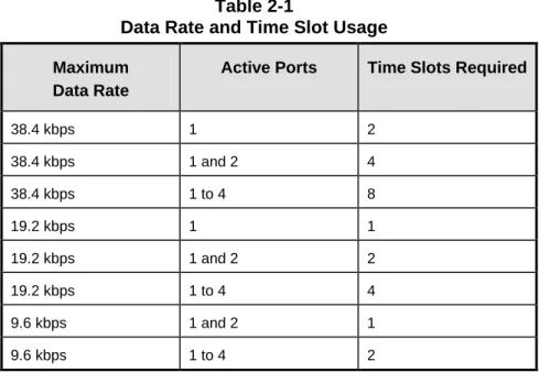
The TERM switch determines whether the module is set up for use in a terminal multiplexer or a drop/insert multiplexer. In a drop/insert multiplexer, it also determines whether the module communicates via the DI-A port or the DI-B port (see Section 2.5, Drop and Insert Operation). RATE and MODE switches set the maximum data rate and whether the module uses one, two, four, or eight time slots. Table 2-1 shows the relation between the data rate, which data ports are activated, and the number of time slots required. The TIME SLOT SELECT switches determine which time slot(s) are used.
Table 2-1
Data Rate and Time Slot Usage
Maximum Data Rate
Active Ports Time Slots Required
38.4 kbps 1 2 38.4 kbps 1 and 2 4 38.4 kbps 1 to 4 8 19.2 kbps 1 1 19.2 kbps 1 and 2 2 19.2 kbps 1 to 4 4 9.6 kbps 1 and 2 1 9.6 kbps 1 to 4 2
TDM BUS
BUS DRIVERS AND RECEIVERS
INTRAPLEX LOGIC ARRAY
SERIAL CONTROL BUS RS232 LINE DRIVERS AND RECEIVERS S2 1 2 3 4 5 6 CAS T1 LOOP TERM REMOTE SRVC DATA IN DATA OUT S3 1 2 3 4 5 6 SET CARD ADDRESS S1 1 2 3 4 5 6 7 8 SELECT TIME SLOT(S) C H2 C H3 C H4 MODULE ADAPTER C H2 C H3 C H4 T X D AT A ( R S-2 3 2 ) SEN D D AT A A/ B ( R S-4 4 9 ) C T S ( R S -23 2 onl y ) CA RR IE R DE T E CT ( R S -232 o nl y ) GR OU N D CH 1 CH 1 SRVC F R A M E L O SS T X D (S D) RX D (RD) LOOP BACK (SET MAX DATA RATE) (SET # OF TIME SLOTS) RATE 1 RATE 0 R X D A T A ( R S-2 3 2 ) R X D AT A A/ B (R S-4 4 9 ) MODE T X D ( SD ) R X D (R D) Figure 2-1
2.2
Transmit Side
The DA-191B converts asynchronous data to a format appropriate for transmission over T1, E1 (2 Mbps), or other digital circuits made up of 64 kbps time slots. Data interface can be either RS-232C or RS-449/422, depending on the module adapter installed (see Appendix A).
The Intraplex Logic Array contains four transitional coders, one for each port. When a coder detects a change in the state of the data, it generates a three-bit word containing information about that transition. The transmit data is sampled at 256 kHz for 38.4 kbps, 128 kHz for 19.2 kbps operation, or 64 kHz for 9.6 kbps operation.
The resulting bitstream passes via the shelf backplane to the common logic module, which multiplexes the data into the aggregate signal for transmission.
When used with an RS-232 module adapter, the transmit side of the module has a Clear to Send (CTS) lead for each of the four ports. This signal is always on, and cannot be controlled by RTS. A green DATA IN LED lights when active transmission begins on any active channel and remains lit while transmission continues.
2.3
Receive Side
The multiplexer common module demultiplexes the aggregate receive signal and passes the data for the selected time slot to the DA-191B module.
When used with an RS-232 module adapter, each port has a Carrier Detect lead which is on during normal operation. While Carrier Detect is on, the module performs transitional decoding, retimes the data, and separates the data channels if more than one data port is active. If the multiplexer loses frame synchronization, all Carrier Detect leads are turned off, and all data ports are set to MARK.
Each channel then goes to an RS-232 line driver, which converts it to RS-232 level and passes it to the module adapter. On an RS-232 module adapter, the RS-232C output signal is sent to the output connector. On an 449 module adapter, the 232 signal is first converted to RS-449/422 and then sent to the output connector.
When the LOOP switch is activated, the receive data coming out of the Intraplex Logic Array is looped back to the transmit input. A green DATA OUT LED lights when on any active channel begins receiving data and remains lit while reception continues.
2.4
Alerts/Alarms
2.5
Drop and Insert Operation
A drop and insert multiplexer operates at a central point on a three (or more) site system. In the example shown in Figure 2-2, Site 2 has a drop and insert multiplexer whose DI-A port is
connected to the transmission line to Site 1, and whose DI-B port is connected to the transmission line to Site 3. Individual payload channels may connect Sites 1 and 2, 1 and 3, or 2 and 3.
Note: In the drop and insert multiplexer at Site 2, a DA-191B module can be set to transmit and receive either via the DI-A port (toward Site 1) or via the DI-B port (toward Site 3), but not both. When a DA-191B is installed in a terminal multiplexer (Site 1 or Site 3), its TERM switch must be set DOWN.
However, when it is installed in a drop and insert multiplexer (Site 2), set the TERM switch DOWN to transmit and receive via the DI-A port (toward Site 1) and UP to transmit and receive via the DI-B port (toward Site 3).
Site 2
Drop and Insert Multiplexer
Through Channels Site 3 Terminal Multiplexer To/From Site 1 (TERM Switch DOWN) To/From Site 3 (TERM Switch UP) Drop and Insert Channels T1 or Other Aggregate Circuit D/I A D/I B Site 1 Terminal Multiplexer To/From Site 2 (TERM Switch DOWN) T1 or Other Aggregate Circuit To/From Site 3 (TERM Switch DOWN) To/From Site 1 (TERM Switch DOWN) To/From Site 2 (TERM Switch DOWN) D A 1 9 1 B D A 1 9 1 B D A 1 9 1 B D A 1 9 1 B D A 1 9 1 B D A 1 9 1 B Figure 2-2
Example of a Three-Site System Using Drop and Insert
2.6
Compatibility With Earlier DA-191 Module Versions
The DA-191B is compatible with all earlier DA-191, DA-191A, and DA-191E versions.However, DA-191 and DA-191E modules can use only one time slot, and can operate in only two modes: one channel with a maximum rate of 19.2 kbps, or two channels with a maximum rate of 9.6 kbps per channel. DA-191A modules have a maximum rate of 19.2 kbps, and can use a
To establish a circuit with a DA-191B at one end and a DA-191, DA-191E, or DA-191A at the far end, configure the DA-191B to match the settings of the older module.
In a system with two DA-191 or DA-191E modules at the far end, a single DA-191B module may be set to use two time slots and establish circuits with both of them.
2.7
Controls and Indicators
The DA-191B has three sets of switches and three LED indicators, as shown on Figures 2-2 and 2-3. The functions of these switches and indicators are described in the following tables.
1 2 3 4 5 6 1 2 3 4 5 6 7 8 TX IN LED SERVICE LED DA-191B RX OUT LED CAS T1 LOOP TERM REMOTE OFF MODE RATE 0 RATE 1 TIME SLOT SELECT Figure 2-3
D AT A IN SR V C R AT E 1 R AT E 0 MO D E TIME SLOT SELECT S2 S1 S3 1 2 ON 3 4 5 6 SCB ADDRESS D AT A O UT
IMPORTANT!!!
All modules must be inserted so that the white eject tab is at the bottom in a full size (5 1/4" high) shelf, and at the right in a compact (1 3/4" high) shelf. C AS T1 L O OP T ER M R E M OT E O FF Figure 2-4
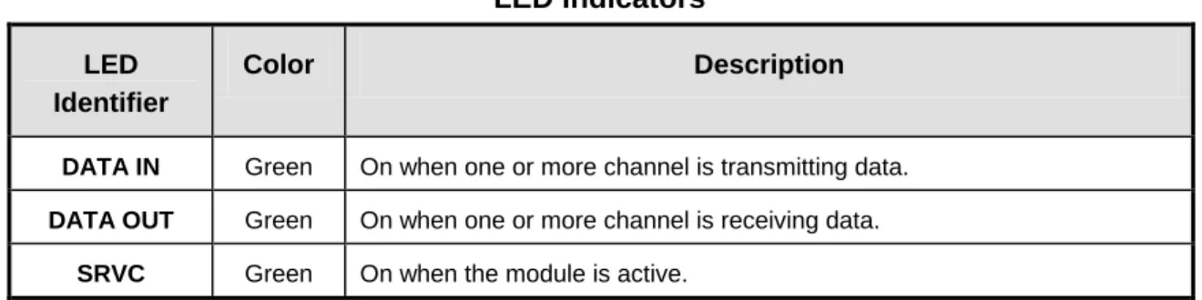
Table 2-2 LED Indicators
LED Identifier
Color Description
DATA IN Green On when one or more channel is transmitting data.
DATA OUT Green On when one or more channel is receiving data.
SRVC Green On when the module is active.
2.7.1
Configuring the Data Ports
The two RATE switches set the maximum data rate for the card, and the MODE switch sets the number of active time slots. These three switches work together to configure the type and number of active data ports, as shown on Table 2-3.
Table 2-3
Data Port Configuration — S1, Positions 1 - 3
Switch Settings Maximum Activates No. Of Restricted E1
RATE 1 RATE 0 MODE Data Rate Port Nos. Time Slots Time Slots
UP DOWN DOWN 38.4 kbps 1 2 15, 16
UP DOWN UP 38.4 kbps 1 and 2 4 13 – 16
UP UP DOWN 38.4 kbps 1 to 4 8 9 – 16
DOWN DOWN DOWN 19.2 kbps 1 1 16
DOWN DOWN UP 19.2 kbps 1 and 2 2 15, 16
UP UP UP 19.2 kbps 1 to 4 4 13 – 16
DOWN UP DOWN 9.6 kbps 1 and 2 1 16
DOWN UP UP 9.6 kbps 1 to 4 2 15, 16
2.7.2
Time Slot Selection
The five TIME SLOT SELECT switches set the starting time slot on the T1 or E1 circuit in which the DA-191B module places its data (see Table 2-4).
IMPORTANT: In an E1 multiplexer set to use CAS signaling, do not use time slot 16 (time slot 16 is reserved for signaling). If the time slot selection would require the use of time slot 16, the card will turn its service off, and it will not operate until the time slot setting is changed.
Table 2-4
Time Slot Selection — S1, Positions 4 - 8
This table lists the first time slot used for data. The number of time slots used depends on the selected rate and mode (see Table 2-3).
Starting Time Slot in a T1 Multiplexer
Starting Time Slot in an E1 Multiplexer Switch S1, Positions* 4 5 6 7 8 1 U U U U U 2 1 U U U U D 3 2 U U U D U 4 3 U U U D D 5 4 U U D U U 6 5 U U D U D 7 6 U U D D U 8 7 U U D D D 9 8 U D U U U 10 9 U D U U D 11 10 U D U D U 12 11 U D U D D 13 12 U D D U U 14 13 U D D U D 15 14 U D D D U 16 15 U D D D D 17 16† D U U U U 18 17 D U U U D 19 18 D U U D U 20 19 D U U D D 21 20 D U D U U 22 21 D U D U D 23 22 D U D D U 24 23 D U D D D 24 D D U U U 25 D D U U D 26 D D U D U 27 D D U D D 28 D D D U U 29 D D D U D 30 D D D D U 31 D D D D D * U = Up, D = Down
† Do not activate time slot 16 in an E1 multiplexer with CAS signaling turned on. The card will not operate (service will turn off).
Table 2-5
Configuration Switches - S2
Switch Setting Description
CAS UP
DOWN
Normal
Reserve time slot 16 for CAS signaling
This switch is active only when the card is set to operate in an E1 multiplexer
T1 UP
DOWN
Sets the module to operate in an E1 (2 Mbps) multiplexer Sets the module to operate in a T1 multiplexer
LOOP UP
DOWN
Normal - loopback off
Activates data loopback - receive data is looped back to transmit input (all channels)
TERM UP
DOWN
Sets the module to operate via the DI-B port in a drop/insert multiplexer (see Section 2.5).
Sets the module to operate in a terminal multiplexer, or via the DI-A port in a drop/insert multiplexer.
REMOTE UP
DOWN
Sets module for local control
Sets module for remote control
OFF UP
DOWN
Normal operation - module is active Turns service off
2.6
Remote Control Interface
DA-191B modules installed in an Intraplex remote controllable shelf can be used under local or remote control. When under remote control, certain configuration parameters can be changed only via the RS-232 remote port on the multiplexer. See the multiplexer operation manual for details on using ISiCL, the Intraplex Simple Command Language.
Before the module can receive remote commands, it must first be assigned a card address. The card address is used to route remote commands and queries to a specific module in a multiplexer. In a full size shelf, it is generally set to the physical slot number the card occupies. It may be set to any number from 1 to 36 which is not in use by another card in the same multiplexer.
The card address is determined by the SCB ADDRESS switch bank (S3) settings, as shown in Table 2-6.
Table 2-6
Card Address Setting - S3
Card Address Switch Settings:* S3, Positions 1 2 3 4 5 6 Card Address Switch Settings:* S3, Positions 1 2 3 4 5 6 1 0 0 0 0 0 1 19 0 1 0 0 1 1 2 0 0 0 0 1 0 20 0 1 0 1 0 0 3 0 0 0 0 1 1 21 0 1 0 1 0 1 4 0 0 0 1 0 0 22 0 1 0 1 1 0 5 0 0 0 1 0 1 23 0 1 0 1 1 1 6 0 0 0 1 1 0 24 0 1 1 0 0 0 7 0 0 0 1 1 1 25 0 1 1 0 0 1 8 0 0 1 0 0 0 26 0 1 1 0 1 0 9 0 0 1 0 0 1 27 0 1 1 0 1 1 10 0 0 1 0 1 0 28 0 1 1 1 0 0 11 0 0 1 0 1 1 29 0 1 1 1 0 1 12 0 0 1 1 0 0 30 0 1 1 1 1 0 13 0 0 1 1 0 1 31 0 1 1 1 1 1 14 0 0 1 1 1 0 32 1 0 0 0 0 0 15 0 0 1 1 1 1 33 1 0 0 0 0 1 16 0 1 0 0 0 0 34 1 0 0 0 1 0 17 0 1 0 0 0 1 35 1 0 0 0 1 1 18 0 1 0 0 1 0 36 1 0 0 1 0 0 * 0 = OFF, 1 = ON
The DA-191B reports itself as a TYPE 115 card. Its remote operation involves two sets of codes: “P” (parameter) codes, and “S” (status) codes, as described in the following two sections.
2.6.1
P Codes
P codes, when used in the parameter field of an ISiCL SET command, allow the user to set parameters on the module via remote control, just like setting the switches on a module under local control.
The two P codes for the DA-191B are P1 and P2. Each is a number from 0 to 255, also
represented as an eight-digit binary number (in parentheses). The binary representation is more useful for setting and interpreting the P codes, because each binary digit (0 or 1) corresponds to the on or off setting for a particular switch on the module. (Only twelve of these sixteen digits correspond to switches; the other four are not used). Table 2-7 describes the meanings of the P codes.
P codes also appear in the response to a CONFIG? query, showing the current parameter settings on the card.
A typical DA-191B response to a CONFIG? query looks like this:
* OK
CHANNEL CARD 3, TYPE 115 UNDER REMOTE CONTROL SRVC = ON
P01 = 35 (B00100011) P02 = 8 (B00001000);
In this sample response, the P codes signify the following:
P1 Module is set to operate with four active ports, maximum data rate 9.6 kbps per port, to use two time slots, starting at time slot #3
P2 Module is set to communicate via the DI-A (TERM) port in a drop/insert multiplexer, the data loopback is off, multiplexer type is E1, and CAS is off (time slot 16 not reserved)
IMPORTANT:When using binary numbers in the parameter field of a SET command, they must be preceded by the letter “B”, as for example:
<MULTIPLEXER ADDRESS>:<CARD ADDRESS>:SET:P02 = B00000011;
In addition to the P codes, it is also possible to turn service on or off for the card by sending
Table 2-7
Remote Configuration Settings (P Codes)
P Code
Digit(s) and
Switch Equivalent Value1 Description
P1
B00000000 ---↑↑↑↑↑
TIME SLOT SELECT
These five digits set the desired time slot(s). See Table 2-8 for a list of possible settings.
B00000000 --↑--- RATE 1
B00000000 -↑---
RATE 0
These three digits together configure the data ports (number of active ports, data rate and time slot usage) for the module.
B00000000 ↑---
MODE
See Table 2-9 for a list of possible settings.
P2 B00000000 ---↑ CAS 0 1 Normal
Reserve time slot 16 for CAS signaling (in an E1 multiplexer only). B00000000 ---↑- T1 0 1
Sets the module to operate in an E1 (2 Mbps) multiplexer. Sets the module to operate in a T1 multiplexer.
B00000000
---↑-- LOOP 0
1
Normal - loopback off.
Loopback active; receive data is looped back to transmit input (all channels).
B00000000
----↑--- TERM 0
1
Sets the module to operate via the DI-B port in a drop/insert multiplexer (see Section 2.5).
Sets the module to operate in a terminal multiplexer, or via the DI-A port in a drop/insert multiplexer.
B00000000
↑↑↑↑---- 0 Not used.
1 These are the only legal values for setting the parameters. Setting any parameter to a value outside its specified range will produce an unpredictable result.
Table 2-8
Time Slot Selection Via Remote Access
This table lists the first time slot used for data. The number of time slots used depends on the selected rate and mode (see Table 2-9).
Starting Time Slot (s)
P1 Settings for Time Slot Select 1 Bxxx00001 2 Bxxx00010 3 Bxxx00011 4 Bxxx00100 5 Bxxx00101 6 Bxxx00110 7 Bxxx00111 8 Bxxx01000 9 Bxxx01001 10 Bxxx01010 11 Bxxx01011 12 Bxxx01100 13 Bxxx01101 14 Bxxx01110 15 Bxxx01111 16 Bxxx10000 17 Bxxx10001 18 Bxxx10010 19 Bxxx10011 20 Bxxx10100 21 Bxxx10101 22 Bxxx10110 23 Bxxx10111 24 Bxxx11000 25 Bxxx11001 26 Bxxx11010 27 Bxxx11011 28 Bxxx11100 29 Bxxx11101 30 Bxxx11110 31 Bxxx11111
† Do not activate time slot 16 in an E1 multiplexer with CAS signaling turned on. The card will not operate (service will turn off).
Table 2-9
Data Port Configuration Via Remote Access
P1 Settings for Mode, Rate 0, and Rate 1 Maximum Data Rate Activates Port Numbers No. Of Time Slots B110xxxxx 38.4 kbps 1 2 B010xxxxx 38.4 kbps 1 and 2 4 B100xxxxx 38.4 kbps 1 to 4 8 B111xxxxx 19.2 kbps 1 1 B011xxxxx 19.2 kbps 1 and 2 2 B000xxxxx 19.2 kbps 1 to 4 4 B101xxxxx 9.6 kbps 1 and 2 1 B001xxxxx 9.6 kbps 1 to 4 2
2.6.2
S Code
There is one S code for the DA-191B. It is a response to a STATUS? query, and indicates transmit and receive activity, as shown in Table 2-10. The S code is shown in both decimal and binary form. A typical response to a STATUS? query looks like this:
* OK
CHANNEL CARD 3, TYPE 115 S01 = 0 (B00000011);
In this example, the S code shows both transmit and receive activity. Table 2-10
Remote Status Queries (S Codes)
S Code
Digit and LED
Equivalent Value Description
S1 B00000000 ---↑ DATA OUT 0 1
No receive activity detected
Receive activity detected on one or more data channels
B00000000
---↑- DATA IN 0
1
No transmit activity detected
Transmit activity detected on one or more data channels
B00000000
Section 3
Installation Procedure
Refer to the figures and tables in the previous section as necessary during this procedure. Power supply and time slot considerations may affect the installation of this module into an existing multiplexer shelf. Refer to the sections on Channel Module Configuration Guidelines
and Adding Channel Modules to Existing Systems in your multiplexer operation manual for more information.
INSPECTION:
Inspect the module for shipping damage. If you suspect damage to the module, call Intraplex Customer Service.
CONFIGURATION:
1. Choose any unused physical slot in the Intraplex multiplexer for installation of this module.
Make sure that the appropriate module adapter is installed at the rear of the slot where you intend to mount this module. Refer to Appendix A in this manual section for information about selecting and installing module adapters.
2. Set the desired port configuration using the RATE 1, RATE 0, and MODE switches (S1, positions 1 - 3), as described in Table 2-3.
3. Select the desired starting time slot using the TIME SLOT SELECT switches (S1, positions 4 - 8), as described in Table 2-4.
4. Set for use in a terminal or drop/insert multiplexer using the TERM switch (S2, position 4): UP to communicate via the DI-B port in a drop/insert multiplexer, DOWN in a terminal multiplexer or to communicate via the DI-A port in a drop/insert multiplexer.
5. Select the multiplexer type using the T1 switch (S2, position 2): UP for E1, DOWN for T1.
6. If this card is being installed in an E1 multiplexer, set the CAS switch (S2, position 1) to the desired position: UP to leave time slot 16 available for payload, DOWN to reserve time slot 16 for CAS signaling.
7. Verify that the data loopback is turned off: LOOP switch (S2, position 3) UP.
8. Set the address for the card using the SCB ADDRESS switch bank (S3), as described in Table 2-6. This step is not necessary unless you will be using the remote access and control feature, but it is advisable to set each card to a different address during installation to simplify the activation of remote operation in the future.
A. For local control operation:
1. Set to local control: REMOTE switch (S2, position 5) UP. 2. Turn service on: OFF switch (S2, position 6) UP.
3. Install the module into the shelf (see MOUNTING, below). B. For remote control operation:
1. Set to local control: REMOTE switch (S2, position 5) UP. 2. Turn service off: OFF switch (S2, position 6) DOWN. 3. Install the module (see MOUNTING, below).
4. Wait 15 seconds; this loads the parameter settings for the card into the shelf common module.
5. Remove the module and set to remote control: REMOTE switch DOWN. Do not turn service on.
6. Reinstall the module.
7. Verify the configuration via remote control by issuing a CONFIG? query. See Section 2.6.2., Remote Configuration Codes, for an explanation of the CONFIG? response.
8. Set service on via remote control (ISiCL SET command, with “SRVC = ON” in the parameter field). You can now change the operating
parameters for the module using ISiCL commands. For details on using the Intraplex Simple Command Language (ISiCL) for remote access and control, consult your multiplexer operation manual.
MOUNTING:
Insert the module into the selected slot in the Intraplex multiplexer.
!!! IMPORTANT:The module must be inserted so that the white ejector tab is at the
Section 4
Testing
When the DA-191B Data Module has been configured and installed, test it for proper operation before putting it into service.
There are two ways you can do the testing:
Local testing using multiplexer equipment loopback, with the system out of service. End-to-end testing using far end module data loopback, with the system in service
but the channel being tested taken out of service. Use the following procedure to test the modules:
1. For local testing, activate the multiplexer equipment loopback following the instructions in your multiplexer operation manual.
For end-to-end testing, set the loopback (LOOP) switch on the far end DA-191B module ON, and set the multiplexer at one end of the circuit to use loop timing.
2. Connect a data error analyzer (Telecommunication Techniques Corp. Fireberd 2000 or equivalent) to the jack for channel one on the back of the module adapter, using an RJ-11 cable.
3. Check for synchronization on the output signal.
4. Send single errors on the transmit side and check for single errors on the receive side. 5. Run for 30 seconds and confirm that the signal remains error-free.
6. Repeat test on each channel set up for use in the current configuration.
7. If you used end-to-end testing, return the LOOP switch at far end to OFF position. The system is now operational.
If there is an apparent malfunction during end to end testing, first check that the configuration at the two ends is identical.
Most problems occur at the common equipment or facility level. Refer to the Troubleshooting
Section 5
Specifications
Asynchronous Data Interface
One-way or full duplex, one to four channel operation, four independent data ports
Data Rates 0 bps to 38.4 kbps each channel
Coding Four 3-bit transitional coders (one for each port) to
minimize data jitter, with mark for idle state
Jitter Dependent on maximum data rate selected:
38.4 kbps = 4 µs p-p 19.2 kbps = 8 µs p-p 9.6 kbps = 16 µs p-p
Time Slots Depending on data rates, any one time slot or up to eight contiguous time slots
RS-232 Interface (MA-404)
Supports TX Data, RX Data, Clear to Send (CTS), Carrier Detect
RS-449/422 Interface (MA-418)
Supports Send Data A, Send Data B, Receive Data A, Receive Data B
Indicators LED indicators for Service On, Data In (Tx activity), and Data Out (Rx activity)
Connector RJ-11 jacks on the Module Adapter
Temperature 0° - 50°C Operating
Humidity 0% - 90% Non-condensing
Appendix A
Module Adapters - DA-191B
The DA-191B Data Module can be installed with one of two optional module adapters, depending on the data interface desired. These are:
• MA-404 - RS-232C, with provision for CTS, TXD, RXD, CD
• MA-418 - RS-449/422, with provision for SD-A, SD-B, RD-A, RD-B
Both of these module adapters provide RJ-11 connectors for the data ports. Active ports are numbers 1 through n, where n is the number of active data channels. Thus, for single channel operation, use the CH. 1 port; for two channels, use the CH. 1 and CH. 2 ports; and so on.
To install either of these Module Adapters: Insert the MA into the rear of the slot that will hold the DA-191B module, secure it with the screws provided, and connect the RJ-11 lines. The following sections define the pin assignments for these MAs.
A.1
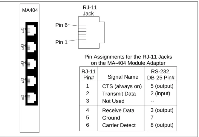
MA-404 Module Adapter
Figure A-1 shows the input jack arrangement and defines the pin assignments for the MA-404. As the figure indicates, the MA-404 has five data ports. Only the ports labeled CH. 1 through CH. 4 are used with the DA-191B module.
RJ-11
Jack
Pin 1
Pin 6
Pin Assignments for the RJ-11 Jacks
on the MA-404 Module Adapter
RJ-11
Pin#
1
2
3
4
5
6
RS-232,
DB-25 Pin#
Signal Name
CTS (always on)
Transmit Data
Not Used
Receive Data
Ground
Carrier Detect
5 (output)
2 (input)
--3 (output)
7
8 (output)
MA404 CH 1 CH 2 CH 3 CH 4 CH 5 Figure A-1A.2
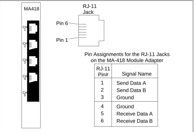
MA-418 Module Adapter
Figure A-2 shows the input jack arrangement and defines the pin assignments for the MA-418.
RJ-11
Jack
Pin 1
Pin 6
Pin Assignments for the RJ-11 Jacks
on the MA-418 Module Adapter
RJ-11
Pin#
1
2
3
4
5
6
Signal Name
Send Data A
Send Data B
Ground
Ground
Receive Data A
Receive Data B
MA418 CH 1 CH 2 CH 3 CH 4 CH 5 Figure A-2Equipment Needed: extractor tool (EX-6 PLCC Extractor), grounding wrist strap (strongly recommended) and mat.
Procedure:
1. Locate a grounded workstation or work area. Attach a grounding wrist strap or make sure you are properly grounded. Arrange all materials needed for the upgrade (modules, replacement programmed devices, and extractor tools).
2. Remove the DA-191B Rev A4 card from the Intraplex multiplexer. 3. Place the card on an available flat surface (antistatic mat for instance).
4. Use the extractor tool to lift the Actel Gate Array (board location U11) away from the board (see dashed circle in the figure below for location of the Actel).
5. Remove one of the new Actels (labeled 4416-9285E) from the packing sleeve. Position and place the new Actel into the sockets vacated by the original Actel. Orient the Actel to match the socket and use minimal pressure to push the new Actel securely into the slot. Refer to the Actel close-up figure below for device orientation.
6. Place one of the REV A6 labels directly over the original REV label on the solder side of the card (located on the leading edge at the bottom).
7. The DA-191B may then be “hot” reinserted into the multiplexer.
8. Confirm operational settings of the DA-191B.