Cable Data Services
DOCSIS® Provisioning of EPON Specifications
DPoE™ Architecture Specification
DPoE-SP-ARCHv1.0-I01-110225
ISSUED
Notice
This DPoE specification is the result of a cooperative effort undertaken by certain member companies of Cable Television Laboratories, Inc. for the benefit of the cable industry and its customers. This document may contain references to other documents not owned or controlled by CableLabs. Use and understanding of this document may require access to such other documents. Designing, manufacturing, distributing, using, selling, or servicing products, or providing services, based on this document may require intellectual property licenses from third parties for technology referenced in this document.
Document Status Sheet
Document Control Number: DPoE-SP-ARCHv1.0-I01-110225Document Title: DPoE™ Architecture Specification Revision History: I01 - Released 2/25/11
Date: February 25, 2011 Status: Work in
Progress
Draft Issued Closed
Distribution Restrictions: Author Only
CL/Member CL/ Member/
Vendor Public
Key to Document Status Codes
Work in Progress An incomplete document, designed to guide discussion and generate feedback that may include several alternative requirements for consideration.
Draft A document in specification format considered largely complete, but lacking review by Members and vendors. Drafts are susceptible to substantial change during the review process.
Issued A stable document, which has undergone rigorous member and vendor review and is suitable for product design and development, cross-vendor interoperability, and for certification testing.
Closed A static document, reviewed, tested, validated, and closed to further engineering change requests to the specification through CableLabs.
Trademarks
Advanced Digital Cable™, CableCARD™, CableHome®, CableLabs®, CableNET®, CableOffice™, CablePC™,
DCAS™, DOCSIS®, DPoE™, EBIF™, eDOCSIS™, EuroDOCSIS™, EuroPacketCable™, Go2BroadbandSM,
M-Card™, M-CMTS™, OCAP™, OpenCable™, PacketCable™, PCMM™, and tru2way® are marks of Cable Television Laboratories, Inc. All other marks are the property of their respective owners.
Contents
1 INTRODUCTION ...1
1.1 DPoE Technology Introduction...1
1.2 Scope ...2 1.3 Goals...2 1.4 Requirements ...3 1.5 Organization of Specifications ...3 1.6 DPoE Specifications ...3 1.7 Reference Architecture ...4
1.8 DPoE Interfaces and Reference Points ...5
2 REFERENCES ...8
2.1 Normative References ...8
2.2 Informative References...9
2.3 Reference Acquisition ...10
3 TERMS AND DEFINITIONS ...11
3.1 DPoE Elements...11
3.2 Other Terms...12
4 ABBREVIATIONS AND ACRONYMS...13
5 DPOE SERVICE REQUIREMENTS...15
5.1 Business Services Overview...15
5.2 Service Requirements ...15
5.3 Single Tenant Businesses ...16
5.4 Multiple Tenant Businesses ...16
5.5 Detailed Service Requirements Introduction ...17
5.6 Private Data Services...18
5.6.1 Ethernet Service...18
5.6.2 Private IP...18
5.7 Internet Service...18
5.7.1 Static Address Service...18
5.7.2 Dynamic Address Service ...19
5.7.3 Transit Service ...19
5.7.4 Peering Function ...19
5.8 Voice Services ...19
5.8.1 Single Line Telephony...19
5.8.2 Multiple Line Telephony ...19
5.9 Vertical Markets ...20
5.9.1 Wholesale Ethernet...20
5.9.2 T1 or T3 Pseudowire ...21
5.9.3 IP-PBX...21
5.9.4 Cell Tower Backhaul ...21
5.9.5 Video Distribution and Transport ...22
5.9.6 Storage Network Services ...22
6 ARCHITECTURAL FOUNDATION ...23
6.1 Forwarding ...23
6.1.1 Ethernet Virtual Connections ...23
6.1.2 Metro Ethernet Services ...23
6.2 Service Integration...24 6.3 Multipoint Architecture ...24 6.4 DOCSIS Emulation ...25 6.5 eDOCSIS ...25 6.6 EPON OAM ...29 7 REQUIREMENTS ...30 7.1 Introduction ...30 7.2 Architectural Elements ...30
7.2.1 DPoE Network Definition...30
7.2.2 DPoE System Definition ...30
7.2.3 DPoE ONU Definition ...30
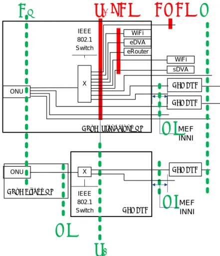
7.2.4 DPoE Standalone ONU Definition ...30
7.2.5 DPoE Bridge ONU Definition ...31
7.3 Interface and Reference Point Detailed Descriptions ...31
7.3.1 DPoE Interfaces ...31
7.3.2 DPoE Reference Points ...32
7.4 Architectural Requirements ...33
7.4.1 Service Based Architecture...33
7.5 Service Model...33
7.5.1 One to One Scheduler to Service Port Mapping...33
7.5.2 Many to One ...36
7.5.3 Any to Any...36
7.5.4 NNI Interfaces...36
7.6 Service and Device Management Architecture...37
7.7 IP Forwarding Model...38
7.7.1 MEF Model...38
7.7.2 MEF Rationale for IP(HSD)...38
7.7.3 DPoE IP(HSD) ...38
7.7.4 DPoE System Future Extensibility...39
7.7.5 IP(HSD) Implementation of MEF with [802.1ad]...39
7.8 eDOCSIS ...41
7.8.1 eDOCSIS on DPoE Standalone ONU...41
7.8.2 eDOCSIS Proxy on DPoE Standalone ONU ...42
7.8.3 eSAFE Discovery ...42
7.8.4 vCM and eCM...42
7.8.5 LCI Extended ...42
APPENDIX I INTRODUCTION TO MULTI-ACCESS OPTICAL NETWORKS...44
APPENDIX II INTRODUCTION TO EPON...45
II.1 Downstream Channel ...45
II.2 Upstream Channel ...45
II.3 Physical Layer ...45
II.4 Data Link ...46
II.5 FEC...46
II.6 Stream-Based FEC Versus Frame-Based FEC ...47
II.7 Upstream Channel and Burst-Mode ...47
II.8 EPON Multi-Point Control Protocol ...48
II.9 Unicast Traffic...49
II.10 IP Multicast...49
II.11 Broadcast Traffic ...50
II.12 P2P Emulation ...50
III.1 Multi-Layer Switching (MLS) and Classification ...51
III.2 MLS Forwarding ...51
III.3 IP(HSD) Implementation with MLS...51
III.4 IP Multicast...52
III.5 MAC Optional ...52
APPENDIX IV EXAMPLE LLID REQUIREMENTS...54
IV.1 Example 1. DPoE ONU #1...55
IV.2 Example 2. DPoE ONU #2...56
IV.3 Example 3. DPoE ONU #3...57
Figures
Figure 1 - DPoE Reference Architecture...5
Figure 2 - DPoE Interfaces and Reference Points ...6
Figure 3 - DPoE Elements ...11
Figure 4 - eDOCSIS Reference Model from Figure 5-1 of [eDOCSIS] ...26
Figure 5 - Simplified and Updated Model of eDOCSIS...26
Figure 6 - eDOCSIS Model Based on Ethernet...27
Figure 7 - DPoE eDOCSIS Adaptation ...27
Figure 8 - DPoE Specifications Splits eDOCSIS ...28
Figure 9 - eDOCSIS to DPoE eDOCSIS Mapping ...29
Figure 10 - DPoE ONU one to one classifies one service, from one port, to one LLID ...34
Figure 11 - DPoE IP(HSD) high level view ...39
Figure 12 - IP(HSD) Implementation of MEF with [802.1ad] ...40
Figure 13 - DPoE eDOCSIS Reference Model ...41
Figure 14 - DPoE Specifications support both embedded and standalone SAFEs...43
Figure 15 - IP(HSD) Implementation of MEF EVCs with MLS...52
Figure 16 - Example 1. DPoE ONU #1 ...55
Figure 17 - Example 2. DPoE ONU #2 ...56
Figure 18 - Example 3. DPoE ONU #3 ...57
Tables
Table 1 - DPoE Specifications...4Table 2 - DPoE Interface and Reference Point Descriptions ...6
Table 3 - IP(HSD) EVCs...40
Table 4 - IP(HSD) EVCs...51
1 INTRODUCTION
Comcast Corporation, Time Warner Cable, and Bright House Networks collaborated to develop the interoperability requirements to support business services products using Ethernet Passive Optical Network (EPON) as an access technology.
DOCSIS Provisioning of EPON (DPoE) is a joint effort of operators, vendors, and suppliers to support EPON technology using existing DOCSIS-based back office systems and processes.
Ethernet PON or EPON is an [802.3] standard for a passive optical network (PON). A PON is a specific type of multi-access optical network. A multi-access optical network is an optical fiber based network technology that permits more than two network elements to transmit and receive on the same fiber. Appendix I has a more detailed explanation of multi-access optical networks.
This version of the DPoE specifications is focused on DOCSIS-based provisioning and operations of Internet Protocol (IP) using DOCSIS High Speed Data (HSD), or IP(HSD) for short, and Metro Ethernet Forum (MEF) services. DPoE Networks offer IP(HSD) services functionally equivalent to DOCSIS networks, where the DPoE System acts like a DOCSIS CMTS and the DPoE System and DPoE Optical Network Unit (ONU) to appear to act like a DOCSIS CM.
1.1 DPoE Technology Introduction
DPoE technology was established with the following common requirements already developed by operators. Each of the participant operators had previously selected 1G-EPON and 10G-EPON as the appropriate technology for one or more applications. EPON is a widely-deployed technology with a sufficient and large supply of vendors offering a variety of products for each component of the access network. 10G-EPON technology is now becoming available and is backwards compatible with 1G-EPON. A 1G-EPON network can be incrementally upgraded to 10G-EPON, adding or replacing ONUs one at a time if required. 1G-EPON and 10G-EPON are compatible with [SCTE 174] (RFoG).
The EPON protocol [802.3ah] and the amendment for 10G-EPON [802.3av] support a centralized operator-based controller (OLT) architecture with low cost Layer 2 access devices (ONU). The basic service mapping architecture in EPON is to map Ethernet (or IP) frame header information (such as addresses, IP DiffServ Code Points, Ethernet Q tag, S-VLAN/C-VLAN ID, ISID, bridge address, or other marking) to a logical circuit called a Logical Link Identifier (LLID) in [802.3ah]. The service function is similar to that used in DOCSIS networks in many ways because it is based on a centralized scheduler and uses an LLID which functions like an SID, supports both unicast and broadcast, and has other similarities.
Existing [802.3ah] EPON systems do interoperate within the strict definitions of 1G-EPON. Experience with lab testing, field trials, and deployments has shown operators that 1G-EPON OLT and ONU systems typically only interoperate with a single port ONU. This is because [802.3ah] specifies the interfaces on the PON (the DPoE TU interface) but does not specify any of the other system interfaces. For example, an OLT from vendor A will register an ONU from vendor B, but it is not possible to construct a VLAN from the DPoE MN interface to an S interface. This is a well-recognized limitation of [802.3ah]. The challenge is that neither 1G-EPON nor 10G-EPON specify OAMP to forward traffic between NNI ports and the PON, or UNI ports and the PON. This is not different from other Ethernet standards. For example, if two Ethernet switches from two different vendors are connected, each switch must typically be configured independently. The challenge for EPON is that the remote device (the ONU) cannot be reached, and therefore cannot be configured. A solution to this problem must then be based on developing a common (standard) method of reaching the controller for the ONU, identifying the ONU capabilities, and
providing that information to the OLT so that it can configure a working end to forwarding service (in both directions).
Even if EPON had solved that provisioning challenge, there are no standard management interfaces for the ongoing operations and maintenance of the network, including fault management, performance management, security, etc. Operators already have fully working and scaled-out systems that solve these challenges for DOCSIS networks. One of the primary goals for DPoE specifications is to use the existing DOCSIS back office infrastructure to scale up EPON-based business services.
1.2 Scope
This specification describes the architecture for DPoE Networks and the organization of the DPoE specifications. Existing business services include one or more of DOCSIS IP and Layer 2 services, baseband and broadband Ethernet services over coaxial cable, Ethernet over fiber with baseband and broadband (CWDM and DWDM), BPON, EPON, and wireless services. The majority of business services (and all residential Internet and voice) customers are supported by the DOCSIS systems and processes. The maturity of both the technology and the back office systems and process allows for a high degree of scaling as evidenced by the growth of IP(HSD) (residential broadband) and more recently voice service, using these existing processes and systems.
This version of the document specifies requirements for these services only:
MEF EPL Service
IP/Internet Service as defined by DOCSIS 3.0 (for IPv4 only)
Other services can be operated over the top of the above two services, but the provisioning, operations, and other requirements for such services are not specified in this version of DPoE. For example, an operator could use a DEMARC device or functions on a DPoE ONU outside of the scope of these specifications to manually or otherwise configure and operate other Metro Ethernet services, such as E-VPL, E-Tree, or E-LAN. This version of DPoE specifications does not specify the provisioning and operations of these services, but vendors could offer, or operators could implement, such "over the top" solutions.
1.3 Goals
Collectively, the operators started the DPoE specification development to accomplish the following objectives:
Identify and document the common requirements for triple play services for business customers over EPON.
Adapt DOCSIS-based back office provisioning and operations models to EPON. This is the core objective of DPoE specifications.
Develop consensus on additional requirements above and beyond DOCSIS specifications to take advantage of the capabilities of EPON. These are focused in the area of Ethernet services and MEF integration.
Continue to leverage the supply chain and economic benefits of a large base of suppliers and high-volume supply chain in optics, subsystems, and network systems based on a commodity EPON technology. Doing so requires adapting operator processes and networks to the EPON system rather than making any changes to the EPON systems.
Positioning DPoE specifications to continue to leverage those same benefits for 10G-EPON.
Work with the established EPON vendor community to assure that these strategies can be effective to mutually develop DPoE Networks, and to create a marketplace for success for multiple vendors to provide solutions for the variety of needs within the operator environment.
1.4 Requirements
Throughout this document, the words that are used to define the significance of particular requirements are capitalized. These words are:
"MUST" This word means that the item is an absolute requirement of this specification. "MUST NOT" This phrase means that the item is an absolute prohibition of this specification. "SHOULD" This word means that there may exist valid reasons in particular circumstances to
ignore this item, but the full implications should be understood and the case carefully weighed before choosing a different course.
"SHOULD NOT" This phrase means that there may exist valid reasons in particular circumstances when the listed behavior is acceptable or even useful, but the full implications should be understood and the case carefully weighed before implementing any behavior described with this label.
"MAY" This word means that this item is truly optional.One vendor may choose to include the item because a particular marketplace requires it or because it enhances the product, for example; another vendor may omit the same item.
1.5 Organization of Specifications
The DPoE specifications are organized around existing DOCSIS specifications. The purpose of matching DPoE specification documents to existing CableLabs DOCSIS, IEEE, IETF, and MEF requirements is to facilitate the mapping of services from existing DOCSIS infrastructure to DPoE infrastructure, and to provide an organization that will be easy to maintain as related (referenced) standards, recommendations, or specifications undergo independent changes.
There are two types of documents in the DPoE specifications. The first includes informative and requirements documents called specifications that detail the specific requirements for products claiming compliance with the specifications. The DPoE specifications also include a new kind of document that does not fit into any of the above categories. The IP Network Elements (IP NE) Requirements [DPoE-SP-IPNEv1.0] are a set of common
requirements for the management of IP network elements that operators have developed, which are above and beyond the requirements in DOCSIS specifications, but are nonetheless required in DOCSIS CMTS products today. These are not specifications because no new protocols or algorithms are provided. Most of the requirements in IP NE are existing requirements based on IEEE, IETF, or other network management standards.
The DPoE documents are detailed in Section 1.6 of this document and duplicated, for reference, in each of the DPoE specifications.
1.6 DPoE Specifications
This document is one in a series of eight (8) documents comprising the DPoE specifications. Collectively these documents represent the operators' requirements for EPON-based commercial services.
Table 1 - DPoE Specifications
Document Document Title Description
DPoE-SP-ARCHv1.0 DPoE Architecture
Specification
DOCSIS Provisioning of EPON introduction, architecture, and narrative. Specifies fundamental architectural
requirements (those that apply to more than one specification). Explains the purpose of each document below.
DPoE-SP-OAMv1.0 DPoE OAM Extensions
Specification
Extensions beyond [802.3ah] and [802.3av] requirements.
DPoE-SP-PHYv1.0 DPoE Physical Layer
Specification
Using the EPON PHY, the DPoE PHY specification makes mandatory some options within EPON and adds some additional requirements.
DPoE-SP-SECv1.0 DPoE Security and
Certificate Specification
Specifications for support for DOCSIS network and system interfaces to provide transparent support of DOCSIS device authentication, code verification, and additional security for a DPoE implementation.
DPoE-SP-IPNEv1.0 DPoE IP Network Element
Requirements
Best practices and operator requirements for IP network element management and operations. This document includes CMTS-like IP router requirements. This document recommends practices not currently covered by any existing DOCSIS specifications.
DPoE-SP-MULPIv1.0 DPoE MAC and Upper Layer Protocols Requirements
Specifications for support of a subset of DOCSIS 3.0 MULPI functionality with additional EPON requirements.
DPoE-SP-MEFv1.0 DPoE Metro Ethernet Forum
Specification
Specifications for Metro Ethernet services added to DOCSIS static configuration provisioning model.
DPoE-SP-OSSIv1.0 DPoE Operations and
Support System Interface Specification
Specifications for support of a subset of DOCSIS 3.0 OSSI functionality with additional EPON requirements.
1.7 Reference Architecture
The DPoE reference architecture identifies the elements that a DPoE Network minimally requires to illustrate and communicate the physical hardware and logical software interfaces between the functional subsystems of the DPoE architecture. The principal elements in the architecture are the DPoE System that resides in the operator network, and the DPoE ONU which may be an off the shelf EPON ONU, EPON SFP-ONU, or an EPON ONU with
additional subsystems. The remaining elements in the architecture are existing servers and systems in the operator’s network. All of the server elements have connectivity through an IP (TCP/IP) network. Transport of bearer traffic, and (in some cases) Layer 2 OAM signaling are available through either IP or Layer 2 Ethernet-based Network Interfaces.
Figure 1 - DPoE Reference Architecture
1.8 DPoE Interfaces and Reference Points
The DPoE interfaces and reference points provide a basis for the description and enumeration of DPoE
specifications for the DPoE architecture. Each interface or reference point indicates a point between separate sub-systems. The reference points have protocols that run across them, or have a common format of bearer traffic (with no signaling protocol). All of the interfaces are bi-directional interfaces that support two-way communications. The protocols in DPoE specifications operate within different layers based on the [802.3], [802.1], IETF, MEF, and CableLabs specifications. The C reference points are uni-directional for upstream (CO) or downstream (CS)
DPoE System IP/Transport Network R ONU DPoE-SP-OSSIv1.0 OSSI SNMP X DPoE-SP-MEFv1.0 MEF EVCs DPoE-SP-PHYv1.0 ODN R R
DPoE Standalone ONU
DPoETM Bridge ONU eDVA IEEE 802.3 (EPON) D TU DPoE-SP-IPNEv1.0 Routing ARP IS-IS OSPF MP-BGP DPoE-SP-IPNEv1.0 SSH/Telnet TACACS+ RADIUS HTTP NTP FTP/SFTP TFTP RSH SNMP OLT DPoE-SP-OAMv1.0 EPON OAM + EPON OAM Extensions
R/X OSS MN IEEE 802.3 MEF INNI L2VPN ONU DEMARC S1 eRouter DOCSIS 3.0 Equivalent IP Service
DEMARC eSAFE EVCs X IEEE 802.3 Frame Labels 802.1 MAC 802.1 q VLAN 802.1ad or q-in-q 802.1ah ISID or MAC-in-MAC IEEE 802.1 Switch IEEE 802.1 Switch LCI S2 DEMARC MEF INNI MI MI MEF INNI CO CS CMCI sDVA WiFi WiFi External eSAFE SNMP External eSAFE EVCs eSAFE SNMP KEY Reference Point
(GREEN) Interface(RED)
MU
DEMARC
MI
Figure 2 - DPoE Interfaces and Reference Points
Table 2 - DPoE Interface and Reference Point Descriptions
Interface or Reference Point Interface or Reference Point Description
MN The MN interface is an [802.3] interface for Ethernet (or MEF or L2VPN emulated) services only. It serves the role of a MEF INNI or L2VPN NSI. It is an NNI for Metro Ethernet services only.
D The D interface is the DOCSIS IP NNI interface. It is an operator network facing interface, sometimes called a Network to Network Interface (NNI) or Network Systems Interface (NSI) in DOCSIS specifications. The D interface allows a DPoE System to communicate with an IP network. The D interface carries all IP management traffic including OSSI and IP NE traffic. The D interface carries all DOCSIS IP service traffic.
TU The TU interface is a short form of expressing the interface between the DPoE System and the DPoE ONU.
C The C reference point is used for explanation of traffic ingress to a DPoE classifier. CO The CO reference point is used for explanation of traffic ingress to a DPoE ONU upstream
classifier.
CS The CS reference point is used for explanation of traffic ingress to a DPoE System
Interface or Reference Point Interface or Reference Point Description
S The S interface is an IEEE 802 interface. The S interface may be an internal interface (such as [802.3] across a GMII SERDES or XGMII interface in an SFP-ONU, SFP+ONU or XFP-ONU) or it may be an external Ethernet interface.
S1 is an interface for a DPoE Standalone ONU. S2 is a reference point used for explanation of
services with the DPoE Bridge ONU.
S1 The S1 interfaces are the general case of all interfaces on a DPoE Standalone ONU. S1
interfaces may be CMCI, LCI, MI, or MU interfaces.
S2 The S2 reference point is used for explanation of traffic ingress to and egress from interfaces
on a DEMARC device in a DPoE System. Although there are no specifications or requirements for the S2 reference point, informative text refers to the S2 reference point to
provide the full context for the use of a DPoE Bridge ONU in a DEMARC device providing Metro Ethernet services.
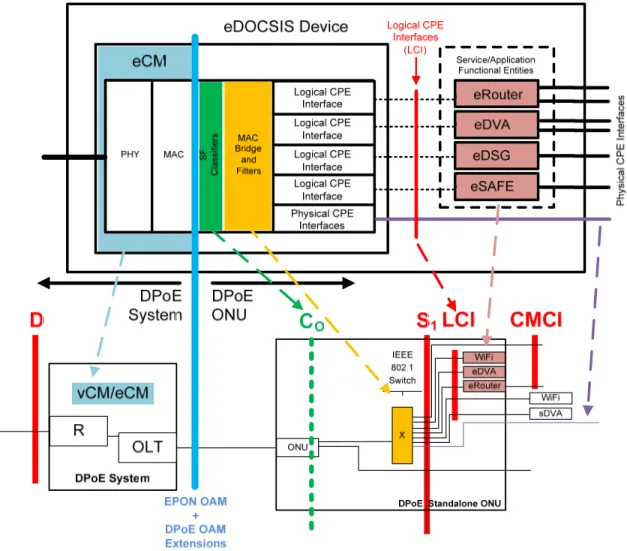
LCI The Logical CPE Interface (LCI) interface is an eDOCSIS interface as defined in
[eDOCSIS]. The eDOCSIS architecture is [802.1d] MAC based according to the DOCSIS 3.0 specifications; however, DOCSIS L2VPN clearly supports [802.1q] switching. In practice, therefore, the eDOCSIS interface consists of a DOCSIS classifier and [802.1] switch as illustrated. The function of a DOCSIS classifier is in part replaced by forwarding (tagging and encapsulation) in MEF and in part covered by classifiers in [DPoE-SP-MULPIv1.0].
CMCI CMCI is the DPoE interface equivalent of the DOCSIS Cable Modem CPE Interface as
defined in [CMCIv3.0]. This is the service interface for DOCSIS-based IP services.
MI MI is usually an S interface (or S reference point) that operates as a MEF INNI. A DPoE ONU that provides a MEF INNI has an MI interface.
A DPoE ONU can have MU as an interface and an MI reference point on different S interfaces in a single DPoE ONU.
The MI interface or reference point is an [802.3] interface (or reference point) between a DPoE ONU and a DEMARC device.
MU MU is usually an S interface (or S reference point) that operates as a MEF UNI. A DPoE ONU that directly provides a MEF UNI (MU) interface has MU as an interface. A DPoE ONU can have MU as an interface and an MI reference point on different S interfaces in a single DPoE ONU.
The MU interface or reference point is an [802.3] interface (or reference point) between a DPoE ONU or a DEMARC device and a customer’s equipment.
2 REFERENCES
2.1 Normative References
In order to claim compliance with this specification, it is necessary to conform to the following standards and other works as indicated, in addition to the other requirements of this specification. Notwithstanding, intellectual property rights may be required to use or implement such normative references. At the time of publication, the editions indicated were valid. All references are subject to revision, and users of this document are encouraged to investigate the possibility of applying the most recent editions of the documents listed below. References are either specific (identified by date of publication, edition number, version number, etc.) or non-specific. For a non-specific reference, the latest version applies.
[802.1] Refers to entire suite of IEEE 802.1 standards unless otherwise specified.
[802.1ah] IEEE Std. 802.1ah-2008, IEEE Standard for Local and Metropolitan Area Networks –
Virtual Bridged Local Area Networks – Amendment 6: Provider Backbone Bridges, January 2008.
[802.1d] IEEE Std 802.1d™-2004, IEEE Standard for Local and Metropolitan Area Networks:
Media Access Control (MAC) Bridges
[802.1q] IEEE Std. 802.1q-2009, IEEE Standard for Local and Metropolitan Area
Networks-Virtual Bridged Local Area Networks, January 2010.
[802.3] IEEE 802.3-2008, Carrier Sense Multiple Access with Collision Detection (CSMA/CD)
access method and Physical Layer specifications, January 2008.
[802.3ah] IEEE 802.3ah™-2004: Amendment to IEEE 802.3™-2005: Media Access Control
Parameters, Physical Layers, and Management Parameters for Subscriber Access Networks, now part of [802.3].
[802.3av] IEEE 802.3AV-2009, IEEE Standard for Information technology-Telecommunications
and information systems-Local and metropolitan area networks-Specific requirements, Part 3: Carrier Sense Multiple Access with Collision Detection (CSMA/CD) Access Method and Physical Layer Specifications Amendment 1: Physical Layer Specifications and Management Parameters for 10Gb/s Passive Optical Networks.
[CMCIv3.0] Data-Over-Cable Service Interface Specifications, Cable Modem to Customer Premise
Equipment Interface Specification, CM-SP-CMCIv3.0, Cable Television Laboratories, Inc.
[DPoE-SP-IPNEv1.0] DPoE-SP-IPNEv1.0, DOCSIS Provisioning of EPON, IP Network Element
Requirements, Cable Television Laboratories, Inc.
[DPoE-SP-MEFv1.0] DPoE-SP-MEFv1.0, DOCSIS Provisioning of EPON, Metro Ethernet Forum
Specification, Cable Television Laboratories, Inc.
[DPoE-SP-MULPIv1.0] DPoE-SP-MULPIv1.0, DOCSIS Provisioning of EPON, MAC and Upper Layer Protocols Requirements, Cable Television Laboratories, Inc.
[eDOCSIS] Data-Over-Cable Service Interface Specifications, eDOCSIS Specification,
2.2 Informative References
This specification uses the following informative references.
[802.1ad] IEEE Std. 802.1ad-2005™, IEEE Standard for Local and Metropolitan Area Networks –
Virtual Bridged Local Area Networks Amendment 4: Provider Bridges, May 2006.
[802.1ag] IEEE Std 802.1ag™-2007, IEEE Standard for Local and metropolitan Area Networks –
Virtual Bridged Local Area Networks Amendment 5: Connectivity Fault Management, December 2007.
[802.1ax] IEEE Std. 802.1ax-2008, IEEE Standard for Local and Metropolitan Area
Networks-Link Aggregation, January 2008.
[802.3ac] IEEE Std. 802.3ac™-1995, IEEE Standard for Carrier Sense Multiple Access with
Collision Detection (CSMA/CD) Access Method and Physical Layer Specifications - Frame Extensions for Virtual Bridged Local Area Network (VLAN) Tagging on 802.3 Networks, January 1995. Now part of [802.3].
[802.3ag] IEEE Std. 802.3ag™-2007, IEEE Standard for Local and Metropolitan Area
Networks-Virtual Bridged Local Area Networks-Amendment 5: Connectivity Fault Management, January 2007.
[802.3as] IEEE Std. 802.3as-™2006, Amendment 3 to IEEE Standard for Information
technology-Telecommunications and information exchange between systems-Local and metropolitan area networks-Specific requirements-Part 3: Carrier Sense Multiple Access with
Collision Detection (CSMA/CD) Access Method and Physical Layer Specifications Amendment 3, November 2006.
[DOCSIS] Refers to DOCSIS 3.0 unless otherwise specified.
[DPoE-SP-OAMv1.0] DPoE-SP-OAMv1.0, DOCSIS Provisioning of EPON, OAM Extensions Specification,
Cable Television Laboratories, Inc.
[DPoE-SP-OSSIv1.0] DPoE-SP-OSSIv1.0, DOCSIS Provisioning of EPON, Operations and Support System
Interface Specification, Cable Television Laboratories, Inc.
[DPoE-SP-PHYv1.0] DPoE-SP-PHYv1.0, DOCSIS Provisioning of EPON, Physical Layer Specification,
Cable Television Laboratories, Inc.
[DPoE-SP-SECv1.0] DPoE-SP-SECv1.0, DOCSIS Provisioning of EPON, Security and Certificate
Specification, Cable Television Laboratories, Inc.
[eRouter] Data-Over-Cable Service Interface Specifications, eRouter Specification,
CM-SP-eRouter, Cable Television Laboratories, Inc.
[L2VPN] Data-Over-Cable Service Interface Specifications, Layer 2 Virtual Private Networks,
CM-SP-L2VPN, Cable Television Laboratories, Inc.
[MEF 14] Metro Ethernet Forum, Abstract Test Suite for Traffic Management Phase 1, November
2005.
[MEF 21] Metro Ethernet Forum, Service OAM and Requirements Framework, Phase 1, April
2007.
[MEF 26] Metro Ethernet Forum, External Network to Network Interface (ENNI) – Phase 1,
January 2010.
[MEF 6] Metro Ethernet Forum, MEF 6.1 Ethernet Services Definitions, Phase 2, April 2008.
[MEF 9] Metro Ethernet Forum, Abstract Test Suite for Ethernet Services at the UNI, October
[MULPIv3.0] Data-Over-Cable Service Interface Specifications, MAC and Upper Layer Protocols Interface Specification, CM-SP-MULPIv3.0, Cable Television Laboratories, Inc.
[OSSIv3.0] Data-Over-Cable Service Interface Specifications, Operations Support System Interface
Specification, CM-SP-OSSIv3.0, Cable Television Laboratories, Inc.
[PHYv3.0] Data-Over-Cable Service Interface Specifications, Physical Layer Specification,
CM-SP-PHYv3.0, Cable Television Laboratories, Inc.
[RFC 2011] IETF RFC 2011, SNMPv2 Management Information Base for the Internet Protocol using
SMIv2, K. McCloghrie, November 1996.
[RFC 2863] IETF RFC 2863, The Interfaces Group MIB, K. McCloghrie, F. Kastenholz, June 2000.
[RFC 3418] IETF RFC 3418/STD0062, Management Information Base (MIB) for the Simple
Network Management Protocol (SNMP), R. Presuhn, Ed., June 2000.
[RFC 4188] IETF RFC 4188, K. Norseth, Ed. and E. Bell, Ed., Definitions of Managed Objects for
Bridges, September 2005.
[RFC 4293] IETF RFC 4293, Management Information Base for the Internet Protocol (IP), S.
Routhier, April 2006.
[RFC 1918] IETF RFC 1918, Address Allocation for Private Internets, February 1996.
[SCTE 174] SCTE 174 2010, Radio Frequency over Glass Fiber-to-the-Home Specification
[SECv3.0] Data-Over-Cable Service Interface Specifications, Security Specification,
CM-SP-SECv3.0, Cable Television Laboratories, Inc.
[SFF-8077i] SFF-8077i 10 Gigabit Small Form Factor Pluggable Module, Revision 4.0, released April
13, 2004.
[SFF-8472] SFF-8472 Specification for Diagnostic Monitoring Interface for Optical Transceivers,
Revision 10.4, released January 2009.
[SFP MSA] INF 8074i Rev 1.0, Small Form-factor Pluggable Multi-Source Agreement, released 12
May 2001.
2.3 Reference Acquisition
Cable Television Laboratories, Inc., 858 Coal Creek Circle, Louisville, CO 80027;
Phone +1-303-661-9100; Fax +1-303-661-9199;
Internet Engineering Task Force (IETF) Secretariat, 48377 Fremont Blvd., Suite 117, Fremont, California
94538, USA, Phone: +1-510-492-4080, Fax: +1-510-492-4001,
Institute of Electrical and Electronics Engineers (IEEE), +1 800 422 4633 (USA and Canada);
SCTE, Society of Cable Telecommunications Engineers Inc., 140 Philips Road, Exton, PA 19341
Phone: +1-800-542-5040, Fax: +1-610-363-5898, Internet:
3 TERMS AND DEFINITIONS
3.1 DPoE Elements
DPoE Network This term means the entire network described in Figure 3 from the D or MN interface to the LCI,
S, MI, or MU interface (see Figure 2 for interface and reference points), depending on the service being described. In no case does the term DPoE Network ever include a DEMARC device.
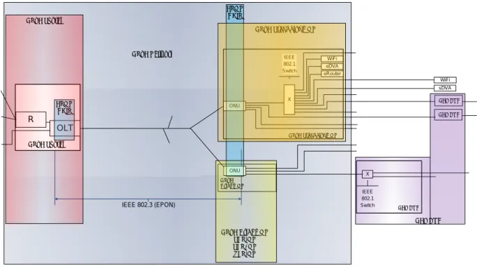
DPoE System This term means all of the collected elements that provide the DPoE function within the
operator’s network facilities. This includes the EPON OLT function, DOCSIS service functions required for the D interface, Metro Ethernet service functions required for the MN interface, and IP NE element management, routing and forwarding functions specified in
[DPoE-SP-IPNEv1.0]. The DPoE System is depicted in Figure 3.
DPoE ONU This term means a DPoE-capable ONU that complies with all of the DPoE specifications. There
are two types of DPoE ONUs. These are the DPoE Standalone ONU and the DPoE Bridge ONU. DPoE
Standalone ONU
This term means a DPoE ONU that is a standalone ONU capable of providing IP or Ethernet services directly to customer premise equipment or transport of traffic to an external DEMARC device.
DPoE Bridge ONU
This term means a DPoE ONU that is capable of [802.1] forwarding but cannot do all of the encapsulation functions required to be a DPoE Standalone ONU. Examples include an SFP-ONU and some simple EPON chipset-only based ONUs.
DEMARC Short form of "Demarcation Device." This term means the device, owned and operated by the
operator that provides the demarcation (sometimes called the UNI interface) to the customer. Some architectures describe this device as the CPE (as in DOCSIS, DSL, or Broadband Forum Models) or the NID (as in the MEF model).
IEEE 802.3 (EPON)
DPoE System
R
ONU
X
DPoE Standalone ONU
DPoE Bridge ONU eDVA OLT ONU DEMARC eRouter DEMARC X IEEE 802.1 Switch IEEE 802.1 Switch DEMARC sDVA WiFi WiFi DPoE System
DPoE Standalone ONU EPON
CHIP
DPoE Bridge ONU SFP-ONU SFP+ONU XFP-ONU DEMARC DPoE Network EPON CHIP
3.2 Other Terms
1G-EPON EPON as defined in [802.3ah]
10G-EPON EPON as defined in [802.3ah] and amended in [802.3av]
Cable Modem CPE Interface CMCI as defined in [MULPIv3.0]
Customer Premise Equipment (CPE)
Customer Premise Equipment as defined in [DOCSIS] Multi-Layer Switching
(MLS)
A switch that can switch based on Layer 2, Layer 3, Layer 4, etc. Ethernet Passive Optical
Network (EPON)
Refers to both 1G-EPON and 10G-EPON collectively EPON Operations and
Maintenance Messaging (OAM)
EPON OAM messaging as defined in [802.3ah] and [DPoE-SP-OAMv1.0]; Ethernet OAM is not the same as EPON OAM; Ethernet OAM is [802.1ag]
Logical CPE Interface LCI as defined in [eDOCSIS]
Network Interface Device (NID)
4 ABBREVIATIONS AND ACRONYMS
This specification uses the following abbreviations:
CMCI Cable Modem CPE Interface
CMIM Cable Modem Interface Mask
CPE Customer Premise Equipment
CoS Class of Service
CTBH Cell Tower Backhaul
CWDM Coarse Wavelength Division Multiplexing
DIA Dedicated Internet Access
DPoE DOCSIS Provisioning of EPON
DR Default Router
DSx Digital Signal (DS1 or DS3)
DWDM Dense Wavelength Division Multiplexing
eCM embedded Cable Modem
eDVA embedded Digital Voice Adapter
ENNI External Network to Network Interface
EPL Ethernet Private Line
EPON Ethernet Passive Optical Network
eSAFE embedded Service/Application Functional Entity
ESP Ethernet Service Path
EVC Ethernet Virtual Connection
E-VPL Ethernet Virtual Private Line
EVP-LAN Ethernet Virtual Private LAN
FEC Forward error correction
Gbps Gigabits per second (as used in the industry)
GBd Gigabaud
IP(HSD) High Speed Data (Broadband Internet Access using DOCSIS)
INNI Internal Network to Network Interface
IP Internet Protocol
I-SID [802.1ah] I-Component Service IDentifier
LCI Logical CPE Interface
LLID Logical Link IDentifier
MEF Metro Ethernet Forum
MEN Metro Ethernet Network
MI MEF INNI Interface at a customer premise
MLS Multi-Layer Switching
MPCP Multi-Point Control Protocol
MPCPDU MPCP Data Unit
MSC Mobile Switching Center
MU MEF UNI Interface
NID Network Interface Device
NNI Network to Network Interface
OAM EPON Operations Administration and Maintenance
OAMP Operations Administration Maintenance and Provisioning
ODN Optical Distribution Network
OLT Optical Line Termination
ONU Optical Network Unit
OSC Optical Splitter Combiner
PB Provider Bridging [802.1ad]
PBB Provider Backbone Bridging [802.1ah]
P2P Point-to-Point
P2PE Point-to-Point Emulation
P2MP Point-to-Multi-Point
PCS Physical Coding Sublayer
PHY Physical Layer
PMA Physical Medium Attachment
PMD Physical Media Dependent (Sublayer)
PON Passive Optical Network
QoS Quality of Service
R IP Router
ROADM Reconfigurable Optical Add-Drop Multiplexer
RS Reconciliation Sublayer
SCB Single Copy Broadcast
sDVA Standalone Digital Voice Adapter
SFP Small Form-factor Pluggable
SFP+ Small Form-factor Pluggable Plus (+)
TPID Tag Protocol Identifier
UNI User Network Interface
vCM Virtual Cable Modem
WDM Wavelength Division Multiplexing
WSC Wireless Switching Center
X IEEE Ethernet Switch (Generic)
5 DPOE SERVICE REQUIREMENTS
The purpose of this section is to document service requirements in sufficient detail to justify specific technical requirements for DPoE specifications. This document and this section do not attempt to identify the size of the markets, explain the business interests, or promote one or more services above any others.
Neither this document nor this section explains the variations of product feature sets required for a specific customer. Again, the focus is on technical requirements. For example, one operator might desire to have a single box ONU solution that fulfills all Ethernet business service customers. Another operator might prefer one ONU product for Ethernet customers below 1Gbps and another for customers above 1Gbps. Other variations might include combinations with other service sets (like IP services, voice, video, etc.), variations in data rate capabilities, variations in packaging and environmental requirements (wall mount, indoor versus outdoor, etc.). None of these variations is explored here. The services requirements described here are those that have an impact on the Operations, Administration, Maintenance, and Provisioning, and data collection for a multi-vendor EPON environment with DOCSIS, IP, and Ethernet controls.
Most of these services require core functionality that is shared across multiple services. Some require additional service-specific functionality.
5.1 Business Services Overview
The majority of business services can be delivered using Ethernet. In the access network, Ethernet can be used to deliver native Ethernet services (as defined by the Metro Ethernet Forum or MEF), or IP services transported over Ethernet. IP can, in turn, be used to deliver private IP (IP-VPN) services or public IP (Internet) services. IP can be used to deliver some storage network services, VoIP, or pseudowire TDM emulation. Pseudowire circuit emulation can be used to provide private line (T1 or T3 for example), IP-PBX, cell tower backhaul, etc.
Ethernet is the least common denominator of all modern telecommunications services. Whether in-house carrier services, wholesale, business services, or even residential, Ethernet has become the foundation for
telecommunications services.
EPON provides a native Ethernet service and is an ideal access and transport technology. Accommodations for IP services provide network and management efficiency. The centralized control of the OLT provides tight scheduler control of both downstream and upstream traffic. EPON is capable of delivering any Ethernet or Ethernet-based service that conforms to IEEE 802 standards.
5.2 Service Requirements
Business services that do now, or may in the future, require EPON-based access/transport include:
Private Data Services
Ethernet Services IP (Public IP/Internet) Voice Services Vertical Markets IP-PBX T1 (Pseudowire)
Cell Tower Backhaul
Ethernet or
T1 and T3 (Pseudowire)
Video Distribution and Transport (internal or external)
Storage network services
In-House Use
Data center applications
Headend / hub applications
Transport between headends and hubs
These services are often complex because it is possible to combine and package these services in a variety of permutations and combinations. For example, a voice service may, to the access network, be simply a VLAN for an operator offering Ethernet transport based IP-PBX services. The same could be true for CTBH. Services can also be combined. For example, one customer might have private Ethernet transport, Internet access, private IP, and multiple voice services (IP trunking, pseudowire, and PSTN services) or any combination in one or more sites.
5.3 Single Tenant Businesses
Single tenant businesses can be served with a single dedicated ONU. Each business customer may have one or more services. A 'service' in DPoE specifications is the network service provided on a single UNI port, such as CMCI for IP(HSD) or MU for MEF, or an LCI for an embedded Service/Application Functional Entity (eSAFE). The analogy for an LLID in DOCSIS specifications is the DOCSIS SF. The DPoE System MUST dedicate one LLID for each service. Similarly, the DPoE ONU MUST use the same dedicated LLID for that service. The LLID is the baseline technology for the guaranteed delivery of each individual service delivered over a DPoE Network.
Since each separate service has separate requirements, service delivery must be guaranteed for each individual service. Probabilistic techniques that are not absolutely controlled or controllable are not sufficient to meet this requirement. Therefore, any QoS technologies that use packet or frame marking and queuing only (without a fixed-time algorithm scheduler) are not acceptable. In particular, the LLID scheduler for EPON is a TDMA algorithm, which guarantees service delivery for each properly configured LLID. Packet and frame marking technologies are still both useful, and required, for traffic management within an individual service; however, this requirement is distinguished from the need to guarantee individual services.
5.4 Multiple Tenant Businesses
Multiple tenant buildings will differ from single tenant business buildings or mixed-use residential and business buildings. Although it is possible, it is not highly practical to operate a multiple tenant business service by using multiple ONUs and fiber splits within the facility.
The most cost-effective use of fiber would utilize a single strand into a building with a single ONU to service multiple customers. The product variations required for different sized facilities, with variations in service
combinations, strongly suggest a modular solution. However, identifying the correct product is not the objective of this effort. Rather, the objective is to identify the baseline requirements for provisioning and operating such a solution. The most flexible solution for both single tenant and multiple tenants will, in some cases, be a modular approach. Such a modular approach could include a DPoE Standalone ONU and a separate DEMARC device or a DPoE Bridge ONU plugged into a DEMARC device.
5.5 Detailed Service Requirements Introduction
Each group of services below can be further broken down into more detailed services that are closer to the product descriptions of individual services that operators offer to their customers.
Private Data Services
Ethernet Service E-LINE EPL E-VPL E-Tree EP-Tree EVP-Tree E-LAN EP-LAN EVP-LAN Private IP (IP-VPN) IP (Public IP/Internet)
IP(HSD) Fixed IP/Internet Service (CMTS IP Routing)
Static Routing with 1 fixed IP address/MAC
Multiple fixed IP address/MAC
Internet Service
RIP based address learning
BGP based address learning
Voice Services
May include IP-PBX services (described below) but categorized as voice
Single line telephony
Multi-line telephony
Vertical Markets
Wholesale Ethernet
T1 or T3 Pseudowire
IP-PBX (Can be implemented as an Ethernet, Private IP, Public IP, or "Voice" service)
Cell Tower Backhaul
Ethernet
T1 or T3 Pseudowire
Multicast services within Metro Ethernet services, or for the IP services, are not explicitly considered in this version of the specifications. Although IP multicast services can be operated on top of any EPON service, just as they can be operated on top of any Ethernet technology, EPON has unique capabilities to introduce greater broadcast and multicast efficiencies because it is a P2MP technology that natively supports broadcast. IP multicast services could be manually provisioned and operated by operators on a DPoE Network. However, this version of the DPoE specifications does not consider the operations, administration, maintenance, or provisioning of IP multicast.
5.6 Private Data Services
5.6.1 Ethernet Service
EPON is a native Ethernet transport for Ethernet service or Metro Ethernet services. Services provided on top of Ethernet can be constructed in a variety of ways. For example an IP service can be constructed by building an Ethernet service from the ONU UNI (the DPoE S interface) to a MEF UNI terminated at an IP router (physical or sub-interface).
Additional variations might include technology variations for operator needs in servicing these requirements. For example, if an operator has two customers in two separate buildings, their needs might be different from two similar customers co-located in a single building. This has a direct correlation to EPON requirements. A single tenant solution with a single ONU might include several services with several ports and thus require a small number of LLIDs. For a multi-tenant solution, it might be necessary to use a DPoE ONU that has more ports to accommodate a larger number of customers. In that case, the number of required LLIDs for the multitenant ONU is expected to be significantly larger.
5.6.2 Private IP
IP service can be constructed with EPON by building an Ethernet service from the ONU UNI (the DPoE S interface) to a MEF UNI terminated at an IP router (physical or sub-interface).
The Ethernet Service could be constructed to another customer or customer site on EPON or any other access technology. That Ethernet service could also be constructed to reach service platforms within the operator's network. Examples include a Class 5 server (switch) for IP-PBX or VoIP-based voice service, an IP router for BGP peering, IGP (RIP or static) routing, an IP router for IP-VPNs, Ethernet switches or virtual Ethernet switches (VPLS, H-VPLS, or Layer 2 bridge groups) for Ethernet services, etc. This is the architecture already widely adopted by operators for converged service transport.
5.7 Internet Service
Internet service can be offered by two different methods in the DPoE specifications. DPoE specifications support both DOCSIS IP(HSD) equivalent service and MEF-based transport to emulate what operators have sometimes called Dedicated Internet Access (DIA).
5.7.1 Static Address Service
5.7.1.1 IP(HSD) Method
Internet service can be offered by two different methods in DPoE specifications. Static address-based services can be implemented in exactly the same manner as with DOCSIS 3.0 services, utilizing either a bridged service to the CMCI interface or the LCI interface with an eRouter as illustrated in Figure 1 and Figure 2.
Since the DPoE architecture is based on Metro Ethernet services as defined by MEF, it is possible to extend the EVC beyond a DPoE ONU by creating another MEF trail from a DPoE LCI interface to a DEMARC device
(directly attached), or a remote DEMARC device (reachable across an Ethernet network). The MU interface on a DEMARC device or MEF UNI interface anywhere in a remote Ethernet network terminates the MEF EVC,
providing the DOCSIS CMCI interface at such a remote location. Although this method is supported, this version of the DPoE specifications does not specify requirements beyond the DPoE Network. Configuration of the DEMARC device, and any MEN between the DPoE ONU and the MEF UNI, is out of the scope of this specification.
5.7.1.2 Ethernet Method
The operator can also provide a static IP address service using [DPoE-SP-MEFv1.0] to provide Ethernet service between the customer equipment and another MEF UNI interface connected to the operator's IP router. While the operator's router for this service may be connected to a MEF UNI interface, the interface on the operator's router does not have to be a DPoE interface.
This service could be implemented with a wide variation of Metro Ethernet service types. For instance, at the MU connected to the operator's default router, the operator could construct a series of EVPLs where the far-end of each EVPL connects to a different customer or customer location, some of which may be on a DPoE Network.
Alternatively, an E-LAN could be used to provide a functionally equivalent IP(HSD) service.
5.7.2 Dynamic Address Service
Dynamic customer address learning via an IGP (such as RIP) can be supported using the same method, where the DPoE S interface is used to provide Metro Ethernet service to an operator router (the DEMARC device) at the customer premise. It can also be supported by using a DPoE Bridge ONU to provide Metro Ethernet service to an operator router that acts as the DEMARC device.
5.7.3 Transit Service
Internet transit service using BGP can be provided using the same Metro Ethernet services specified in [DPoE-SP-MEFv1.0].
5.7.4 Peering Function
Operators could use DPoE Networks for peering with (non-paying) Internet peers in exactly the same manner as for transit service.
5.8 Voice Services
Voice services are not directly supported in this version of the DPoE specifications. VoIP applications other than PacketCable 2.0 can be supported with VoIP or DS1 pseudowire 'over the top' using Ethernet or IP over Ethernet services of DPoE.
5.8.1 Single Line Telephony
PacketCable voice service is not directly supported in this version of the DPoE specifications.
5.8.2 Multiple Line Telephony
5.9 Vertical Markets
A vertical market is a market for telecommunications services that requires specific services or functions in the network services or management of the network services. Vertical markets often require additional functionality such as specialized network management services, on-demand or custom provisioning capability, and non-standard network interface support from customer premise equipment.
DPoE specifications do not contain any requirements that were designed specifically for a vertical market. However, the architecture for DPoE Networks was designed to allow 'over the top' management of services either within a standalone DPoE ONU or beyond the DPoE S interface or reference point on the far side of a DEMARC device as illustrated in Figure 1 and Figure 2.
Support for over the top control, signaling, and management is provided by EVCs across the CO reference point for
DPoE Bridge ONU implementations. Such a management connection is no different than other EVCs. For a DPoE Standalone ONU, there are three possible models for signaling and management. The first is an embedded model. In the embedded model, an EVC extends from the DPoE System to an eSAFE within an eDOCSIS device (a DPoE ONU) across the LCI interface. This EVC is terminated on the DPoE System. In the second model, the operator would construct an over-the-top EVC through the S1 interface where there is a single
EVC on a single S1 interface. In the third model, the operator would construct an over-the-top EVC within an
ELINE or EVPL through an S1 interface. Such a model could, for example, be used to provide a management
connection (such as a VLAN) to a DEMARC device over the same S1 interface carrying bearer traffic as illustrated
in Figure 2. In both over-the-top models the constructed EVC could terminate on some other device, such as an MU on another DPoE system, which connects to some operator's service management network.
One or more EVCs can be constructed to allow either combined or separate logical circuits for signaling,
management, and bearer traffic. Those EVCs can be provisioned across the MEN to another customer on EPON or any other access technology. The EVC could also be provisioned back to service platforms within the operator's network. Examples include a Class 5 server (switch) for IP-PBX or VoIP-based voice service, an IP router for BGP peering, IGP (RIP or static) routing, an IP router for IP-VPNs, Ethernet switches, or virtual Ethernet switches (VPLS, H-VPLS, or Layer 2 bridge groups) for Ethernet services, etc. This is the architecture already widely adopted by operators for converged service transport.
5.9.1 Wholesale Ethernet
The service requirements for wholesale Ethernet in the access network are defined by MEF. Wholesale Ethernet differs from direct business services only in back office operations and in inter-carrier Network to Network Interface (NNI), which MEF calls the External NNI (ENNI). The current [MEF 26] specifications are based on manually mapping Ethernet [802.1ad] tags between MEF Metro Ethernet Networks (MEN). Like DPoE, [MEF 26] is organized into phases that will deliver progressively more complex services. [MEF 26] is the Phase I ENNI for MEF. Carrier interconnection is outside of the scope of the access network, and therefore, not defined by DPoE. EPON is well-suited to wholesale Ethernet. It can provide Metro Ethernet services with granular control as accurate as single 1kbps in each direction on each EVC. As an [802.3] Ethernet protocol, 1G-EPON and 10G-EPON cannot transport frames larger than those permitted by [802.3] of 2000 bytes1. Because 1G-EPON was developed prior to the Amendment of [802.3] based on [802.3as] (for 2000 bytes), most 1G-EPON implementations are limited to 1600 bytes. The frame size requirements for DPoE Networks are specified in [DPoE-SP-MULPIv1.0].
1
IEEE 802.3 support for 1518 byte payload remains the same in both 1G-EPON and 10G-EPON. The additional 82 bytes (1600 byte total) in 1G-EPON or additional 482 bytes (2000 byte total) in 10G-EPON are for frame overhead. Frame overhead is used
5.9.2 T1 or T3 Pseudowire
DSx emulation over IP (over Ethernet) can be utilized to provide T1 or T3 access services. Latency and variation in latency over time (jitter) in EPON are well-bounded by the maximum delay in the OLT scheduler (per PON). Although there are no EPON-specific standards for DSx emulation over EPON, any DSx pseudowire solutions for Ethernet or IP can be transported over EPON.
T1 can be used for variety of applications ranging from customer service-agnostic private line to PBX extensions, carrier wholesale, cell tower backhaul, or other specific services.
Although jitter in DSx emulation is minimal, pseudowire solutions are not accurate enough to meet the requirements of ITU-T G.824, which specifies the DSx hierarchy for timing signals. In particular, the lack of an absolute
synchronous signal leaves wander as an outstanding problem for pseudowire solutions. This challenge is not specific to EPON.
EPON is capable of native T1 transport without IP. Although some products support DSx over EPON, neither EPON nor DPoE Networks have specific DSx standards at this time. DPoE specifications do not preclude such support, which may be implemented provided that the operation of such services does not affect DPoE operation, including the management and provisioning of both ONU-specific and total PON bandwidth and scheduling (QoS or CoS) specifications and requirements.
5.9.3 IP-PBX
PBX services can be supported just like any other IP service. Although there are no specific provisions for IP-PBX, there are a variety of methods to support IP-PBX over EPON or DPoE. Both require the manual provisioning of EPON bandwidth. IP-PBX could be implemented by:
IP through LCI interface over EPON transport through the D interface to a remote IP-PBX
Using the DOCSIS 1.1 IP service solution (bridged to DPoE System router).
Using the DOCSIS 3.0 IP service solution (bridged or routed with eRouter on DPoE Standalone ONU to DPoE System router).
MEF-based Ethernet transport solution
Using the MEF solution to transport an EVC from a call platform across the DPoE Network and through an MI interface to a DEMARC device with an IP-PBX or with an IP-PBX attached.
Using the MEF solution to transport an EVC from a call platform across the DPoE Network and through an MU interface to an IP-PBX attached.
The latter is possibly the most flexible option. An EVC can be constructed from the S interface to a Class 5 server (switch) operating the IP PBX service. Such services have already been successfully deployed by operators using EPON and can be supported by [DPoE-SP-MEFv1.0].
5.9.4 Cell Tower Backhaul
Cell tower backhaul (CTBH) requires either or both DSx and Ethernet services. DSx CTBH can be supported using DSx pseudowire, non-standard DSx over Ethernet, or DSx over EPON solutions as described above.
An EVC can be constructed from the MU (or via an S interface to a DEMARC providing an external MEF UNI) interface to a Mobile Switching Center (MSC) or Wireless Switching Center (WSC). For Ethernet, the service can be delivered as an EVPL to meet MSC or WSC Ethernet aggregation requirements. For DSx emulation, the EVPL can terminate at a pseudowire service aggregation device. Such services have already been successfully deployed by operators using EPON and can be supported by [DPoE-SP-MEFv1.0].
5.9.5 Video Distribution and Transport
Video can be transported over EPON, within a facility or between facilities, using video over IP or video over Ethernet. Native video transport over Ethernet is compatible with current Gigabit Ethernet video technologies. Video distribution using EPON within a facility does not require DPoE specifications because it will typically not be a dynamic access configuration environment, but rather a static provisioned implementation.
Video transport over EPON for third parties can be supported by using IP(HSD) forwarding or MEF forwarding as specified in [DPoE-SP-MULPIv1.0] and [DPoE-SP-MEFv1.0].
5.9.6 Storage Network Services
DPoE specifications do not contain any specific requirements or recommendations for storage network services. As with all EPON services, EPON can only support IEEE standard frame sizes. As an IEEE 802 Ethernet protocol, 1G-EPON and 10G-1G-EPON cannot transport frames larger than those permitted by [802.3] of 2000 bytes2. Because 1G-EPON was developed prior to the Amendment of [802.3] based on [802.3as] (for 2000 bytes), most 1G-1G-EPON implementations are limited to 1600 bytes. The frame size requirements for DPoE Networks are specified in [DPoE-SP-MULPIv1.0].
Jumbo frames are often requested by customers for Storage Area Networks (SANs). EPON cannot support jumbo frames. EPON maximum frame sizes are based on [802.3] specifications. Although it is possible to design an EPON system that uses larger frame sizes, such a system would go beyond the [802.3] specifications and potentially create additional complexity, such as the increase in jitter that would come with greater variation in frame size.
Some storage services such as iSCSI do not require (although they optionally support) jumbo frames. For these services, EPON can be used for storage network transport by delivering Ethernet with [DPoE-SP-MEFv1.0].
2
IEEE 802.3 support for 1518 byte payload remains the same in both 1G-EPON and 10G-EPON. The additional 82 bytes (1600 byte total) in 1G-EPON or additional 482 bytes (2000 byte total) in 10G-EPON are for frame overhead. Frame overhead is used
6 ARCHITECTURAL FOUNDATION
6.1 Forwarding
The foundation for all DPoE services is an Ethernet service model as described by MEF. Both the Metro Ethernet services and IP services are based on a common Metro Ethernet service architecture.
6.1.1 Ethernet Virtual Connections
The basic unit of services in this version of DPoE specifications is an Ethernet Connection as defined by MEF. MEF defines an Ethernet Virtual connection (EVC) between user-defined end points called User to Network Interfaces or UNI. As in MEF, the EVC is the least common denominator of service for DPoE.
In [802.1ad], the term S-VLAN typically refers to a Service (S) VLAN, and the term C-VLAN typically refers to a Customer (C) VLAN. In telecommunications access services implemented by DPoE, for example, the S-VLAN and C-VLAN are used as "outer" and "inner" tags (like q-in-q) without respect to their typical meaning in [802.1ad]. A DPoE Network can be used to provide a MEF TRAN-trail in the First Mile or Last Mile or both. In this version of DPoE, First and/or Last Mile provisioning are independent of each other.
IP services are implemented over the top of Metro Ethernet services to allow for:
More than one CMCI interface on a DPoE ONU
Uniform forwarding and multiplexing model
Uniform QoS rules in the access network
Extensible architecture beyond the access platform into the operator MEN
Extensible architecture beyond the access platform into a customer premise MEN
Interoperability with other MEF systems
Allow for remote DOCSIS devices by extending the [eDOCSIS] logical bridged Ethernet [802.1] model (LCI interface) beyond the "CM" (or in this case the DPoE ONU) to external [802.1] bridges across a common Metro Ethernet service model (which is also based on [802.1] forwarding). Each LCI interface MUST support exactly one eSAFE (either embedded in the ONU or external).
For some services, the EVC may terminate at a service solution within the hub. For other services, the EVC may traverse a Layer 2 transport (what MEF calls a Metro Ethernet Network or MEN) to a remote UNI within the operator's network or at another customer premise. On top of each EVC, additional services such as IP can be implemented. In other words, the fundamental building block of services delivered with DOCSIS Provisioning of EPON will be an EVC from (either a DEMARC device to) a DPoE ONU to a DPoE System. From the DPoE System, the DPoE EVC trail can be "spliced" into Ethernet transports (real or virtual) or "terminated" at an IP router interface for IP transport and services. When an IP routing function is operated on the DPoE System, the IP service can be provisioned by DPoE. When an IP routing function is not operated on the DPoE System, the IP service cannot be provisioned by DPoE.
6.1.2 Metro Ethernet Services
Metro Ethernet services require a variety of architectural needs. These include single box MEF solution, support for external NIDs (which we call DEMARC) devices, and many types of INNI interfaces at the MN. Each service that MEF describes needs to be supported over each of these different models. MEF itself supports [802.1d], [802.1q],
q-in-q, [802.1ad] (C tag only), and [802.1ad] (Provider Bridged) frames. MEF also offers a variety of QoS parameters.
DPoE Networks are capable of supporting all Metro Ethernet services. Full DOCSIS service automation is limited by the work required to develop the service models and automate DOCSIS file-based provisioning and operations. The specifications for Metro Ethernet services are described in [DPoE-SP-MEFv1.0].
6.1.3 Internet Services
DPoE Networks support MEF UNI based EVCs, but extends the use of EVCs not only for UNI interfaces, but also for soft UNI interfaces. A soft UNI interface is an interface that acts like a MEF UNI interface, but which is not a UNI interface. DOCSIS IP services, for example, are implemented using an EVC from a DPoE ONU Ethernet port to an IP Router function within the DPoE System. The DOCSIS IP service (sometimes called High Speed Data or IP(HSD) is a broadband Internet access service. It is implemented using DPoE specifications in one of two ways. DOCSIS 1.1 equivalent service is a "bridged" service from the customer premise through a DPoE ONU LCI interface to a default router (DR) operating on a DPoE System. The "bridge" (as it is called in DOCSIS specifications) is implemented in DPoE Networks as an EVC from the DPoE ONU LCI interface to the DPoE System. The second implementation is [eRouter], which operates an IP router within the DPoE ONU. In this implementation, the EVC goes from the router in the DPoE System to an LCI interface on an eRouter (which is a type of eSAFE) in a DPoE ONU that is operating as an eDOCSIS CM.
Each DOCSIS IP serving group (IP-SG as identified in [DPoE-SP-MULPIv1.0]) can be associated with a single [802.1ad] S-VLAN. Each customer is mapped into a single [802.1ad] C-VLAN ID (VLAN).
DPoE Networks are capable of supporting all DOCSIS IP-based services. One fundamental distinction between DOCSIS and DPoE Networks is that support for Ethernet services in DPoE Networks is native, and does not need to be tunneled or emulated. IP-based encapsulation for Ethernet service transport is, therefore, not required. The IP(HSD) and VoIP IP services can be implemented over EVCs as described above. The specifications for IP services are described in [DPoE-SP-MULPIv1.0].
6.2 Service Integration
In DOCSIS the service provisioning and services are tied closely together. This remains the case with DPoE specifications. DPoE specifications use the EPON LLID as the primary mechanism for mapping Metro Ethernet service instances to the MAC and MAC sub-layers in order to provide consistent Quality of Service based on the TDM capabilities of EPON. An EPON LLID is logically equivalent to an SF in DOCSIS. IP(HSD) services in DPoE Networks always operate over Metro Ethernet service, and therefore IP(HSD) also uses this common model.. This is accomplished by mapping each Metro Ethernet service EVC to one LLID. This provides a simple, but scalable, architecture limited by the available number of LLIDs on a DPoE ONU or on each EPON.
6.3 Multipoint Architecture
There is one distinct way that EPON is very different from DOCSIS and Ethernet. That difference is derived from the multi-access architecture of EPON. EPON is fundamentally a multi-access optical fiber network. Although it can be used to provide broadcast and unicast services just like DOCSIS, the multi-access function in EPON does not operate as it does in DOCSIS. Broadcast services in EPON are natively supported at the physical layer due to the properties of the underlying physical fiber plant (passive forward split optical distribution network). EPON supports both forward broadcast and unicast when using the MAC. Unlike DOCSIS, return transmissions are non-broadcast. This difference is because the fiber architecture for a PON passively optically combines the return path signals, over time, in the feeder portion of the ODN. The EPON TDMA implementation features a master scheduler in the OLT to time division multiplex upstream burst laser transmissions. The portion of fiber in the ODN from the splitter to the customer premise is a dedicated access medium that is a non-broadcast transmission path in the reverse


![Figure 4 - eDOCSIS Reference Model from Figure 5-1 of [eDOCSIS]](https://thumb-us.123doks.com/thumbv2/123dok_us/9682325.2456796/32.918.121.794.179.514/figure-edocsis-reference-model-figure-edocsis.webp)