ABOUT THIS USER’S GUIDE
INTENDED AUDIENCE
This manual is intended for people who want to configure the CGN2’s features via its Graphical User Interface (GUI).
HOW TO USE THIS USER’S GUIDE
This manual contains information on each the CGN2’s GUI screens, and describes how to use its various features.
Use the Introduction (page 12) to see an overview of the topics covered in this manual.
Use the Table of Contents (page 7), List of Figures (page 10) and List of Tables
(page 11) to quickly find information about a particular GUI screen or topic.
Use the Index (page 110) to find information on a specific keyword.
Use the rest of this User’s Guide to see in-depth descriptions of the CGN2’s features.
RELATED DOCUMENTATION
Quick Installation Guide: see this for information on getting your CGN2 up and running right away. It includes information on system requirements, package contents, the installation procedure, and basic troubleshooting tips.
Online Help: each screen in the CGN2’s Graphical User Interface (GUI) contains a Help button. Click this button to see additional information about configuring the screen.
DOCUMENT CONVENTIONS
Bulleted paragraphs are used to list items, and to indicate options.
1
Numbered paragraphs indicate procedural steps.NOTE: Notes provide additional information on a subject.
Warnings provide information about actions that could harm you or your device.Product labels, field labels, field choices, etc. are in bold type. For example:
A mouse click in the Graphical User Interface (GUI) is denoted by a right angle bracket ( > ). For example:
means that you should click Settings in the GUI, then Advanced settings. A key stroke is denoted by square brackets and uppercase text. For example:
CUSTOMER SUPPORT
For technical assistance or other customer support issues, please consult your Hitron representative.
Select UDP to use the User Datagram Protocol.
Click Settings > Advanced Settings.
DEFAULT CREDENTIALS
The CGN2’s default login credentials are as follows. For more information, see
Logging into the CGN2 on page 23.
Copyright 2012 Hitron Technologies. All rights reserved. All trademarks and registered trademarks used are the properties of their respective owners.
DISCLAIMER: The information in this User’s Guide is accurate at the time of writing. This User’s Guide is provided “as is” without express or implied warranty of any kind. Neither Hitron Technologies nor its agents assume any liability for inaccuracies in this User’s Guide, or losses incurred by use or misuse of the information in this User’s
Table 1: Default Credentials
Username cusadmin Password password
COMPLIANCES
FCC INTERFERENCE STATEMENT
This equipment has been tested and found to comply with the limits for a Class B digital device pursuant to Part 15 of the FCC Rules. These limits are designed to provide reasonable protection against radio interference in a commercial
environment.
This equipment can generate, use and radiate radio frequency energy and, if not installed and used in accordance with the instructions in this manual, may cause harmful interference to radio communications.
Operation of this equipment in a residential area is likely to cause interference, in which case the user, at his own expense, will be required to take whatever measures are necessary to correct the interference. If this equipment does cause harmful interference to radio or television reception, which can be determined by turning the equipment off and on, the user is encouraged to try to correct the interference by one of the following measures:
Reorient or relocate the receiving antenna.
Increase the separation between the equipment and receiver.
Connect the equipment into an outlet on a circuit different from that to which the receiver is connected.
Consult the dealer or an experienced radio/TV technician for help.
The device complies with Part 15 of the FCC Rules. Operation is subject to the following two conditions: (1) This device may not cause harmful interference, and (2) this device must accept any interference received, including interference that may cause undesired operation.
FCC Caution: Any changes or modifications not expressly approved by the party responsible for compliance could void the user’s authority to operate this equipment. IEEE 802.11b or 802.11g operation of this product in the U.S.A is firmware-limited to channels 1 through 11.
FCC Radiation Exposure Statement:
This equipment complies with FCC radiation exposure limits set forth for an uncontrolled environment. This equipment should be installed and operated with minimum distance 20cm between the radiator & your body.
This transmitter must not be co-located or operating in conjunction with any other antenna or transmitter.
The availability of some specific channels and/or operational frequency bands are country dependent and are firmware programmed at the factory to match the intended destination. The firmware setting is not accessible by the end user.
Note to CATV System Installer - The cable distribution system should be grounded (earthed) in accordance with ANSI/NFPA 70, the National Electrical Code (NEC), in particular Section 820.93, Grounding of Outer Conductive Shield of a Coaxial Cable. 107 SMCD3G3-CCR 4-Port Gateway Administrator Manual
TABLE OF CONTENTS
About This User’s Guide ... 2
Compliances ... 5
Table of Contents ... 7
List of Figures ... 10
List of Tables ... 11
Introduction ... 12
1.1 CGN2 Overview ... 12 1.1.1 Key Features ... 13 1.2 Hardware Connections ... 14 1.3 LEDs ... 18 1.4 IP Address Setup ... 211.4.1 Manual IP Address Setup ... 22
1.5 Logging into the CGN2 ... 23
1.6 GUI Overview ... 24
1.7 Resetting the CGN2 ... 25
Status ... 26
2.1 Cable Overview ... 26
2.1.1 DOCSIS ... 26
2.1.2 IP Addresses and Subnets ... 27
2.1.2.1 IP Address Format ... 27 2.1.2.2 IP Address Assignment ... 27 2.1.2.3 Subnets ... 28 2.1.3 DHCP ... 29 2.1.4 DHCP Lease ... 30 2.1.5 MAC Addresses ... 30
2.1.6 Routing Mode ... 31
2.1.7 Configuration Files ... 31
2.1.8 Downstream and Upstream Transmissions ... 31
2.1.9 Cable Frequencies ... 31
2.1.10 Modulation ... 32
2.1.11 TDMA, FDMA and SCDMA ... 32
2.2 The System Info Screen ... 33
2.3 The Initialization Screen ... 37
2.4 The CM Status Screen ... 38
2.5 The Password Screen ... 41
2.6 The Capability Screen ... 42
WAN/LAN ... 45
3.1 WAN/LAN Overview ... 45
3.1.1 WAN and LAN ... 45
3.1.2 LAN IP Addresses and Subnets ... 46
3.1.3 DNS and Domain Suffix ... 46
3.1.4 Debugging (Ping and Traceroute) ... 46
3.2 The IP Screen ... 47
3.3 The Shared Media Screen ... 50
3.4 The Debug Screen ... 51
3.5 The Backup Screen ... 52
Firewall ... 54
4.1 Firewall Overview ... 54
4.1.1 Firewall ... 54
4.1.2 Intrusion detection system ... 55
4.1.3 Ping ... 55 4.1.4 MAC Filtering ... 55 4.1.5 IP Filtering ... 55 4.1.6 Port Forwarding ... 56 4.1.7 Port Triggering ... 56 4.1.8 DMZ ... 56
4.3.1 Adding or Editing an IP Filtering Rule ... 63
4.4 The Forwarding Screen ... 65
4.4.1 Adding or Editing a Port Forwarding Rule ... 67
4.5 The Port Triggering Screen ... 69
4.5.1 Adding or Editing a Port Triggering Rule ... 71
4.6 The DMZ Screen ... 72
Parental Control ... 74
5.1 Parental Control Overview ... 74
5.1.1 Website Blocking ... 74
5.2 The Website Blocking Screen ... 75
5.3 The Scheduling Screen ... 77
5.4 The Email / Syslog Alert Screen ... 79
Wireless ... 83
6.1 Wireless Overview ... 83
6.1.1 Wireless Networking Basics ... 83
6.1.2 Architecture ... 83
6.1.3 Wireless Standards ... 84
6.1.4 Service Sets and SSIDs ... 84
6.1.5 Wireless Security ... 85
6.1.5.1 WPS ... 85
6.1.6 WMM ... 86
6.2 The Setup Screen ... 86
6.3 The Access Control Screen ... 93
6.4 The Advanced Screen ... 95
6.4.1 Configuring WMM Parameters ... 103
Troubleshooting ... 107
LIST OF FIGURES
Figure 1: Application Overview ...13
Figure 2: Hardware Connections ...15
Figure 3: Power Adaptor ...18
Figure 4: LEDs ...19
Figure 5: Login ...23
Figure 6: GUI Overview ...24
Figure 7: The Status > System Info Screen ...34
Figure 8: The Status > Initialization Screen ...37
Figure 9: The Status > CM Status Screen ...39
Figure 10: The Status > Password Screen ...42
Figure 11: The Status > Capability Screen ...43
Figure 12: The WAN/LAN > IP Screen ...48
Figure 13: The WAN/LAN > Shared Media Screen ...51
Figure 14: The WAN/LAN > Debug Screen ...52
Figure 15: The WAN/LAN > Backup Screen ...53
Figure 16: The Firewall > Firewall Options Screen ...57
Figure 17: The Firewall > Filter Setting Screen ...59
Figure 18: The Firewall > Filter Settings > Add/Edit Screen ...63
Figure 19: The Firewall > Forwarding Screen ...65
Figure 20: The Firewall > Forwarding > Add/Edit Screen ...67
Figure 21: The Firewall > Port Triggering Screen ...69
Figure 22: The Firewall > Port Triggering > Add/Edit Screen ...71
Figure 23: The Firewall > DMZ Screen ...73
Figure 24: The Parental Control > Web Site Blocking Screen ...75
Figure 25: The Parental Control > Scheduling Screen ...78
Figure 26: The Parental Control > Email / Syslog Alert Screen ...79
Figure 27: Add Target Email Address ...81
Figure 28: The Wireless > Setup Screen ...87
Figure 29: WPS PIN ...89
Figure 30: The Wireless > Access Control Screen ...93
LIST OF TABLES
Table 1: Default Credentials ...4
Table 2: Hardware Connections ...16
Table 3: LEDs ...19
Table 4: GUI Overview ...24
Table 5: Private IP Address Ranges ...28
Table 6: IP Address: Decimal and Binary ...28
Table 7: Subnet Mask: Decimal and Binary ...29
Table 8: The Status > System Info Screen ...35
Table 9: The Status > CM Status Screen ...39
Table 10: The Status > Password Screen ...42
Table 11: The Status > Capability Screen ...43
Table 12: The WAN/LAN > IP Screen ...48
Table 13: The WAN/LAN > Shared Media Screen ...51
Table 14: The WAN/LAN > Debug Screen ...52
Table 15: The LAN > Backup Screen ...53
Table 16: The Firewall > Firewall Options Screen ...57
Table 17: The Firewall > Filter Setting Screen ...60
Table 18: The Firewall > Filter Settings > Add/Edit Screen ...64
Table 19: The Firewall > Forwarding Screen ...65
Table 20: The Firewall > Forwarding > Add/Edit Screen ...68
Table 21: The Firewall > Port Triggering Screen ...69
Table 22: The Firewall > Port Triggering > Add/Edit Screen ...71
Table 23: The Firewall > DMZ Screen ...73
Table 24: The Parental Control > Web Site Blocking Screen ...76
Table 25: The Parental Control > Scheduling Screen ...78
Table 26: The Parental Control > Email / Syslog Alert Screen ...80
Table 27: The Wireless > Setup Screen ...87
Table 28: The Wireless > Access Control Screen ...94
Table 29: The Wireless > Advanced Screen ...97
1
INTRODUCTION
This chapter introduces the CGN2 and its GUI (Graphical User Interface). It contains the following sections:
CGN2 Overview on page 12
Hardware Connections on page 14
LEDs on page 18
IP Address Setup on page 21
Logging into the CGN2 on page 23
GUI Overview on page 24
Resetting the CGN2 on page 25
1.1
CGN2 OVERVIEW
Your CGN2 is a NAT-capable cable modem and wireless access point that allows you to connect your computers, wireless devices, and other network devices to one another, and to the Internet via the cable connection.
Computers with a wired connection to the CGN2 are on the Local Area Network (LAN), computers with a wireless connection to the CGN2 are on the Wireless Local Area Network (WLAN) and the CGN2 connects to the service provider over the Wide Area Network (WAN).
Figure 1: Application Overview
1.1.1
KEY FEATURES
The CGN2 provides:
Internet connection to cable modem service via CABLE port (F-type RF connector)
Local Area Network connection via four 10/100/1000 Mbps (megabits per second) Ethernet ports
Dynamic Host Configuration Protocol (DHCP) for devices on the LAN
LAN troubleshooting tools (Ping and Traceroute)
IEEE 802.11b/g/n wireless MIMO (Multiple-In, Multiple-Out) networking, allowing speeds of up to 300Mbps
Wireless security: WEP, WPA-PSK and WPA2-PSK encryption, Wifi Protected Setup (WPS) push-button and PIN configuration, MAC filtering,
Wired security: stateful inspection firewall with intrusion detection system, IP and MAC filtering, port forwarding and port triggering, De-Militarized Zone (DMZ) and event logging
Settings backup and restore
Secure configuration interface, accessible by Web browser
1.2
HARDWARE CONNECTIONS
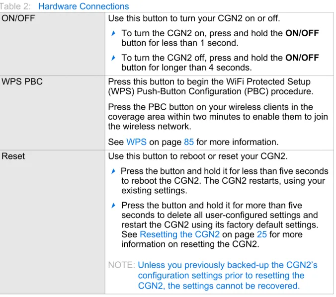
Table 2: Hardware Connections
ON/OFF Use this button to turn your CGN2 on or off.
To turn the CGN2 on, press and hold the ON/OFF
button for less than 1 second.
To turn the CGN2 off, press and hold the ON/OFF
button for longer than 4 seconds.
WPS PBC Press this button to begin the WiFi Protected Setup (WPS) Push-Button Configuration (PBC) procedure. Press the PBC button on your wireless clients in the coverage area within two minutes to enable them to join the wireless network.
See WPS on page 85 for more information. Reset Use this button to reboot or reset your CGN2.
Press the button and hold it for less than five seconds to reboot the CGN2. The CGN2 restarts, using your existing settings.
Press the button and hold it for more than five seconds to delete all user-configured settings and restart the CGN2 using its factory default settings. See Resetting the CGN2 on page 25 for more information on resetting the CGN2.
NOTE: Unless you previously backed-up the CGN2’s configuration settings prior to resetting the CGN2, the settings cannot be recovered.
USB The CGN2 provides one USB 2.0 host port, allowing you to plug in a USB flash disk for mounting and sharing through the LAN interfaces via the Samba protocol (network neighborhood).
The CGN2 supports the following Windows file systems:
FAT16
FAT32
NTFS
USB devices must not drain more than 500mA from the USB port. USB devices requiring more than 500mA should be provided with their own power source(s).LAN1 Use these ports to connect your computers and other network devices, using Category 5 or 6 Ethernet cables with RJ45 connectors.
LAN2 LAN3 LAN4
1.3
LEDS
This section describes the CGN2’s LEDs (lights).
CABLE Use this to connect to the Internet via an F-type RF cable.
POWER Use this to connect to the 12v/2A power adapter that came with your CGN2.
NEVER use another power adapter with your
CGN2. Doing so could harm your CGN2.Figure 3: Power Adaptor
Figure 4: LEDs
Table 3: LEDs
LED STATUS DESCRIPTION
WIRELESS Off The wireless network is not enabled.
Green, steady The wireless network is enabled, and no data is being transmitted or received over the wireless network.
Green, blinking The wireless network is enabled, and data is being transmitted or received over the wireless network. Bi-color Wi-Fi Protected Setup (WPS) is in operation.
LAN 1~4 Off No device is connected to the relevant LAN port. Green, blinking A device is connected to the relevant LAN port via a
Fast Ethernet (100Mbps) link, and is transmitting or receiving data.
Green, steady A device is connected to the relevant LAN port via a Fast Ethernet (100Mbps) link, but is not transmitting or receiving data.
Blue, blinking A device is connected to the relevant LAN port via a Gigabit Ethernet (1000Mbps) link, and is
transmitting or receiving data.
Blue, steady A device is connected to the relevant LAN port via a Gigabit Ethernet (1000Mbps) link, but is not
transmitting or receiving data.
Status Blinking The CGN2’s cable modem is registering with the service provider’s CMTS.
On The CGN2’s cable modem has successfully
registered with the service provider and is ready for data transfer.
US Green, blinking The CGN2 is searching for an upstream frequency on the CABLE connection.
Green, steady The CGN2 has successfully located and locked onto an upstream frequency on the CABLE
connection.
Blue The CGN2 is engaged in channel bonding on the upstream connection.
Off There is no upstream activity on the CABLE
connection.
DS Green, blinking The CGN2 is searching for a downstream frequency on the CABLE connection.
Green, steady The CGN2 has successfully located and locked onto a downstream frequency on the CABLE
connection.
Blue The CGN2 is engaged in channel bonding on the downstream connection.
Off There is no downstream activity on the CABLE
connection.
When you turn on the CGN2, the LEDs light up in the following order:
Power
US
DS
Status
The ETH 1~4 LEDs light up as soon as there is activity on the relevant port, and the WIRELESS LED lights up once the wireless network is ready.
1.4
IP ADDRESS SETUP
Before you log into the CGN2’s GUI, your computer’s IP address must be in the same subnet as the CGN2. This allows your computer to communicate with the CGN2.
NOTE: See IP Addresses and Subnets on page 27 for background information.
The CGN2 has a built-in DHCP server that, when active, assigns IP addresses to computers on the LAN. When the DHCP server is active, you can get an IP address automatically. The DHCP server is active by default.
If your computer is configured to get an IP address automatically, or if you are not sure, try to log in to the CGN2 (see Logging into the CGN2 on page 23).
If the login screen displays, your computer is already configured correctly.
If the login screen does not display, either the CGN2’s DHCP server is not active or your computer is not configured correctly. Follow the procedure in Manual IP Address Setup on page 22 and set your computer to get an IP address
automatically. Try to log in again. If you cannot log in, follow the manual IP address setup procedure again, and set a specific IP address as shown. Try to log in again.
NOTE: If you still cannot see the login screen, your CGN2’s IP settings may have been changed from their defaults. If you do not know the CGN2’s new address, you should return it to its factory defaults. See Resetting the CGN2 on page 25. Bear in mind that ALL user-configured settings are lost.
1.4.1
MANUAL IP ADDRESS SETUP
By default, your CGN2’s local IP address is 192.168.0.1. If your CGN2 is using the default IP address, you should set your computer’s IP address to be between
192.168.0.2 and 192.168.0.254.
NOTE: If your CGN2 DHCP server is active, set your computer to get an IP address automatically in step 5. The CGN2 assigns an IP address to your computer. The DHCP server is active by default.
Take the following steps to manually set up your computer’s IP address to connect to the CGN2:
NOTE: This example uses Windows XP; the procedure for your operating system may be different.
1
Click Start, then click Control Panel.2
In the window that displays, double-click Network Connections.3
Right-click your network connection (usually Local Area Connection) and clickProperties.
4
In the General tab’s This connection uses the following items list, scroll down and select Internet Protocol (TCP/IP). Click Properties.5
You can get an IP address automatically, or specify one manually:If your CGN2’s DHCP server is active, select Get an IP address automatically.
If your CGN2’s DHCP server is active, select Use the following IP address. In the IP address field, enter a value between 192.168.0.2 and
192.168.0.254 (default). In the Subnet mask field, enter 255.255.255.0
(default).
NOTE: If your CGN2 is not using the default IP address, enter an IP address and subnet mask that places your computer in the same subnet as the CGN2.
Your computer now obtains an IP address from the CGN2, or uses the IP address that you specified, and can communicate with the CGN2.
1.5
LOGGING INTO THE CGN2
Take the following steps to log into the CGN2’s GUI.
NOTE: You can log into the CGN2’s GUI via the wireless interface. However, it is strongly recommended that you configure the CGN2 via a wired connection on the LAN.
1
Open a browser window.2
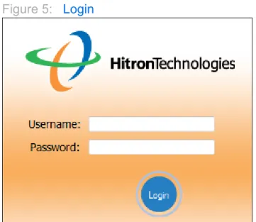
Enter the CGN2’s IP address (default 192.168.0.1) in the URL bar. The Loginscreen displays.
Figure 5: Login
3
Enter the Username and Password. The default login username is cusadmin, and the default password is password.NOTE: The Username and Password are case-sensitive; “password” is not the same as “Password”.
4
Click Login. The System Info screen displays (see The System Info Screen on page 33).1.6
GUI OVERVIEW
This section describes the CGN2’s GUI.
Figure 6: GUI Overview
Each item in the Primary Navigation Bar has its own chapter in this User's Guide; items in the Secondary Navigation Bar have their own section within a chapter.
Table 4: GUI Overview
Primary
Navigation Bar Use this section to move from one part of the GUI to another. Secondary
Navigation Bar Use this section to move from one related screen to another. Main Window Use this section to read information about your CGN2’s
1.7
RESETTING THE CGN2
When you reset the CGN2 to its factory defaults, all user-configured settings are lost, and the CGN2 is returned to its initial configuration state.
There are two ways to reset the CGN2:
Press the RESET button on the CGN2, and hold it in for ten seconds or longer.
Click WAN/LAN > Backup. In the screen that displays, click the Factory Reset
button.
The CGN2 turns off and on again, using its factory default settings.
NOTE: Depending on your CGN2’s previous configuration, you may need to re-configure your computer’s IP settings; see IP Address Setup on page 21.
2
STATUS
This chapter describes the screens that display when you click Status in the toolbar. It contains the following sections:
Cable Overview on page 26
The System Info Screen on page 33
The Initialization Screen on page 37
The CM Status Screen on page 38
The Password Screen on page 41
The Capability Screen on page 42
2.1
CABLE OVERVIEW
This section describes some of the concepts related to the Cable screens.
2.1.1
DOCSIS
The Data Over Cable Service Interface Specification (DOCSIS) is a
telecommunications standard that defines the provision of data services) Internet access) over a traditional cable TV (CATV) network.
2.1.2
IP ADDRESSES AND SUBNETS
Every computer on the Internet must have a unique Internet Protocol (IP) address. The IP address works much like a street address, in that it identifies a specific
location to which information is transmitted. No two computers on a network can have the same IP address.
2.1.2.1 IP ADDRESS FORMAT
IP addresses consist of four octets (8-bit numerical values) and are usually
represented in decimal notation, for example 192.168.1.1. In decimal notation, this means that each octet has a minimum value of 0 and a maximum value of 255. An IP address carries two basic pieces of information: the “network number” (the address of the network as a whole, analogous to a street name) and the “host ID” (analogous to a house number) which identifies the specific computer (or other network device).
2.1.2.2 IP ADDRESS ASSIGNMENT
IP addresses can come from three places:
The Internet Assigned Numbers Agency (IANA)
Your Internet Service Provider
You (or your network devices)
IANA is responsible for IP address allocation on a global scale, and your ISP assigns IP addresses to its customers. You should never attempt to define your own IP addresses on a public network, but you are free to do so on a private network. In the case of the CGN2:
The public network (Wide Area Network or WAN) is the link between the cable connector and your Internet Service Provider. Your CGN2’s IP address on this network is assigned by your service provider.
The private network (in routing mode - see Routing Mode on page 31) is your Local Area Network (LAN) and Wireless Local Area Network (WLAN), if enabled. You are free to assign IP addresses to computers on the LAN and WLAN manually, or to allow the CGN2 to assign them automatically via DHCP (Dynamic Host Configuration Protocol). IANA has reserved the following blocks of IP addresses to be used for private networks only:
If you assign addresses manually, they must be within the CGN2’s LAN subnet.
2.1.2.3 SUBNETS
A subnet (short for sub-network) is, as the name suggests, a separate section of a network, distinct from the main network of which it is a part. A subnet may contain all of the computers at one corporate local office, for example, while the main network includes several offices.
In order to define the extent of a subnet, and to differentiate it from the main network, a subnet mask is used. This “masks” the part of the IP address that refers to the main network, leaving the part of the IP address that refers to the sub-network.
Each subnet mask has 32 bits (binary digits), as does each IP address:
A binary value of 1 in the subnet mask indicates that the corresponding bit in the IP address is part of the main network.
A binary value of 0 in the subnet mask indicates that the corresponding bit in the IP address is part of the sub-network.
For example, the following table shows the IP address of a computer (192.168.1.1) expressed in decimal and binary (each cell in the table indicates one octet):
Table 5: Private IP Address Ranges
FROM... ...TO
10.0.0.0 10.255.255.255 172.16.0.0 172.31.255.255 192.168.0.0 192.168.255.255
Table 6: IP Address: Decimal and Binary
192 168 0 1
The following table shows a subnet mask that “masks” the first twenty-four bits of the IP address, in both its decimal and binary notation.
This shows that in this subnet, the first three octets (192.168.1, in the example IP address) define the main network, and the final octet (1, in the example IP address) defines the computer’s address on the subnet.
The decimal and binary notations give us the two common ways to write a subnet mask:
Decimal: the subnet mask is written in the same fashion as the IP address:
255.255.255.0, for example.
Binary: the subnet mask is indicated after the IP address (preceded by a forward slash), specifying the number of binary digits that it masks. The subnet mask
255.255.255.0 masks the first twenty-four bits of the IP address, so it would be written as follows: 192.168.1.1/24.
2.1.3
DHCP
The Dynamic Host Configuration Protocol, or DHCP, defines the process by which IP addresses can be assigned to computers and other networking devices
automatically, from another device on the network. This device is known as a DHCP server, and provides addresses to all the DHCP client devices.
In order to receive an IP address via DHCP, a computer must first request one from the DHCP server (this is a broadcast request, meaning that it is sent out to the whole network, rather than just one IP address). The DHCP server hears the requests, and responds by assigning an IP address to the computer that requested it.
If a computer is not configured to request an IP address via DHCP, you must
configure an IP address manually if you want to access other computers and devices on the network. See IP Address Setup on page 21 for more information.
By default, the CGN2 is a DHCP client on the WAN (the CATV connection). It
broadcasts an IP address over the cable network, and receives one from the service provider. By default, the CGN2 is a DHCP server on the LAN; it provides IP
addresses to computers on the LAN which request them.
Table 7: Subnet Mask: Decimal and Binary
255 255 255 0
2.1.4
DHCP LEASE
“DHCP lease” refers to the length of time for which a DHCP server allows a DHCP client to use an IP address. Usually, a DHCP client will request a DHCP lease renewal before the lease time is up, and can continue to use the IP address for an additional period. However, if the client does not request a renewal, the DHCP server stops allowing the client to use the IP address.
This is done to prevent IP addresses from being used up by computers that no longer require them, since the pool of available IP addresses is finite.
2.1.5
MAC ADDRESSES
Every network device possesses a Media Access Control (MAC) address. This is a unique alphanumeric code, given to the device at the factory, which in most cases cannot be changed (although some devices are capable of “MAC spoofing”, where they impersonate another device’s MAC address).
MAC addresses are the most reliable way of identifying network devices, since IP addresses tend to change over time (whether manually altered, or updated via DHCP).
Each MAC address displays as six groups of two hexadecimal digits separated by colons (or, occasionally, dashes) for example 00:AA:FF:1A:B5:74.
NOTE: Each group of two hexadecimal digits is known as an “octet”, since it represents eight bits.
Bear in mind that a MAC address does not precisely represent a computer on your network (or elsewhere), it represents a network device, which may be part of a computer (or other device). For example, if a single computer has an Ethernet card (to connect to your CGN2 via one of the LAN ports) and also has a wireless card (to connect to your CGN2 over the wireless interface) the MAC addresses of the two cards will be different. In the case of the CGN2, each internal module (cable modem module, Ethernet module, wireless module, etc.) possesses its own MAC address.
2.1.6
ROUTING MODE
When your CGN2 is in routing mode, it acts as a gateway for computers on the LAN to access the Internet. The service provider assigns an IP address to the CGN2 on the WAN, and all traffic for LAN computers is sent to that IP address. The CGN2 assigns private IP addresses to LAN computers (when DHCP is active), and transmits the relevant traffic to each private IP address.
NOTE: When DHCP is not active on the CGN2 in routing mode, each computer on the LAN must be assigned an IP address in the CGN2’s subnet manually.
When the CGN2 is not in routing mode, the service provider assigns an IP address to each computer connected to the CGN2 directly. The CGN2 does not perform any routing operations, and traffic flows between the computers and the service provider. Routing mode is not user-configurable; it is specified by the service provider in the CGN2’s configuration file.
2.1.7
CONFIGURATION FILES
The CGN2’s configuration (or config) file is a document that the CGN2 obtains automatically over the Internet from the service provider’s server, which specifies the settings that the CGN2 should use. It contains a variety of settings that are not present in the user-configurable Graphical User Interface (GUI) and can be specified only by the service provider.
2.1.8
DOWNSTREAM AND UPSTREAM TRANSMISSIONS
The terms “downstream” and “upstream” refer to data traffic flows, and indicate the direction in which the traffic is traveling. “Downstream” refers to traffic from the service provider to the CGN2, and “upstream” refers to traffic from the CGN2 to the service provider.
2.1.9
CABLE FREQUENCIES
Just like radio transmissions, data transmissions over the cable network must exist on different frequencies in order to avoid interference between signals.
The data traffic band is separate from the TV band, and each data channel is separate from other data channels.
2.1.10
MODULATION
Transmissions over the cable network are based on a strong, high frequency periodic waveform known as the “carrier wave.” This carrier wave is so called because it “carries” the data signal. The data signal itself is defined by variations in the carrier wave. The process of varying the carrier wave (in order to carry data signal
information) is known as “modulation.” The data signal is thus known as the “modulating signal.”
Cable transmissions use a variety of methods to perform modulation (and the “decoding” of the received signal, or “demodulation”). The modulation methods defined in DOCSIS 3 are as follows:
QPSK: Quadrature Phase-Shift Keying
QAM: Quadrature Amplitude Modulation
QAM TCM: Trellis modulated Quadrature Amplitude Modulation
In many cases, a number precedes the modulation type (for example 16 QAM). This number refers to the complexity of modulation. The higher the number, the more data can be encoded in each symbol.
NOTE: In modulated signals, each distinct modulated character (for example, each audible tone produced by a modem for transmission over telephone lines) is known as a symbol.
Since more information can be represented by a single character, a higher number indicates a higher data transfer rate.
2.1.11
TDMA, FDMA AND SCDMA
Time Division Multiple Access (TDMA), Frequency Division Multiple Access (FDMA) and Synchronous Code Division Multiple Access (SCDMA) are channel access methods that allow multiple users to share the same frequency channel.
TDMA allows multiple users to share the same frequency channel by splitting transmissions by time. Each user is allocated a number of time slots, and transmits during those time slots.
SCDMA allows multiple users to share the same frequency channel by assigning a unique orthogonal code to each user.
2.2
THE SYSTEM INFO SCREEN
Use this screen to see general information about your CGN2’s hardware, its software, and its connection to the Internet.
NOTE: Most of the information that displays in this screen is for troubleshooting purposes only. However, you may need to use the MAC Address information when setting up your network.
The following table describes the labels in this screen.
Table 8: The Status > System Info Screen
Device Information
System Time This displays the current date and time.
System Uptime This displays the number of days, hours, minutes and seconds since the CGN2 was last switched on or rebooted.
Model Name This displays the device’s model name.
SW Version This displays the version number of the software that controls the CGN2.
HW Version This displays the version number of the CGN2’s physical hardware.
RF MAC This displays the Media Access Control (MAC) address of the CGN2’s RF module. This is the module that connects to the Internet through the CATV connection.
Serial Number This displays a number that uniquely identifies the device. RG Status This displays whether or not the CGN2 is in Residential
Gateway (RG) mode.
When the CGN2 is in Residential Gateway mode, ON
displays. When the CGN2 is not in Residential Gateway mode, OFF displays.
Wifi Status This displays whether or not the CGN2’s wireless network is active.
When the CGN2’s wireless network is active, ON displays. When the CGN2’s wireless network is not active, OFF
displays.
NAT Status This displays whether or not the CGN2’s Network Address Translation (NAT) feature is active.
When NAT is active, ON displays. When NAT is not active,
OFF displays.
DHCP Status This displays whether or not the CGN2’s DHCP server is active.
When the DHCP server is active, ON displays. When the DHCP server is not active, OFF displays.
Firewall Status This displays whether or not the CGN2’s firewall is active. When the firewall is active, ON displays. When the firewall is not active, OFF displays.
WAN Information
WAN Address This field displays the CGN2’s IP address on the WAN (Wide Area Network) interface.
Subnet Mask This field displays the CGN2’s WAN subnet mask.
Gateway Address This field displays the address of the device on the WAN to which the CGN2 is connected.
DNS Server This field displays the Domain Name Servers that the CGN2 uses to resolve domain names into IP addresses. Uptime This displays the number of hours, minutes and seconds
that the CGN2 has been connected to another device over the WAN interface.
Traffic Count This displays the number of bytes received and sent on the WAN interface.
Wireless Information
SSID This displays the wireless network’s Service Set Identifier. This is the name of the wireless network, to which wireless clients connect.
Wireless Mode This displays the type of wireless network that the CGN2 is using.
Channel This displays the wireless channel on which the CGN2 is transmitting and receiving.
Security Type This displays the type of security the CGN2’s wireless network is currently using.
Cipher type This displays the type of encryption that the wireless network’s security is using:
TKIP displays if it is using the Temporal Key Integrity Protocol.
AES displays if it is using the Advanced Encryption Standard.
TKIP and AES displays if it allows clients using either encryption type to connect to the CGN2.
SSID MAC This displays the Media Access Control (MAC) address of the wireless module, to which wireless clients connect. LAN Status
2.3
THE INITIALIZATION SCREEN
This screen displays the steps successfully taken to connect to the Internet over the
CABLE connection.
Use this screen for troubleshooting purposes to ensure that the CGN2 has
successfully connected to the Internet; if an error has occurred you can identify the stage at which the failure occurred.
NOTE: This screen displays when you first log in to the CGN2.
Click Status > Initialization. The following screen displays.
Figure 8: The Status > Initialization Screen
Private LAN IP
Address This displays the IP address of the CGN2’s Ethernet module. This is the IP address you use to connect with the CGN2’s admin interface via the LAN ports.
Subnet Mask This displays the CGN2’s LAN subnet mask.
Uptime This displays the number of hours, minutes and seconds that the CGN2 has been connected to another device over the LAN interface.
Traffic Count This displays the number of bytes received and sent on the LAN interface.
For each step:
Process displays when the CGN2 is attempting to complete a connection step.
Success displays when the CGN2 has completed a connection step.
2.4
THE CM STATUS SCREEN
Use this screen to discover information about:
The nature of the upstream and downstream connection between the CGN2 and the device to which it is connected through the CABLE interface.
IP details of the CGN2’s WAN connection.
You can also configure the CGN2’s downstream center frequency. Click Status > CM Status. The following screen displays.
Figure 9: The Status > CM Status Screen
The following table describes the labels in this screen.
Table 9: The Status > CM Status Screen
CM Configuration File
Name This displays the name of the configuration file that the CGN2 downloaded from your service provider. This file provides the CGN2 with the service parameter data that it needs to perform its functions correctly.
Network Access This displays whether or not your service provider allows you to access the Internet over the CABLE connection.
Permitted displays if you can access the Internet.
Denied displays if you cannot access the Internet. Tune Channel
Downstream Frequency This displays the center frequency in Megahertz (MHz) at which the CGN2 connects over the CABLE interface. If you want the CGN2 to use a different center
frequency, enter it in the field and click Apply.
NOTE: Do not change the frequency unless you have a good reason to do so.
Upstream ID This displays the ID number of the channel on which the upstream signal is to be transmitted. When an upstram connection cannot be made on the specified channel, the CGN2 attempts to connect on the next channel. If you want the CGN2 to attempt to connect on a different channel, enter it in the field and click Apply.
NOTE: Do not change the channel unless you have a good reason to do so.
Downstream
NOTE: The downstream signal is the signal transmitted to the CGN2.
Frequency (MHz) This displays the actual frequency in Megahertz (MHz) of each downstream data channel to which the CGN2 is connected.
Modulation This displays the type of modulation that each downstream channel uses.
Signal Power (dBmV) This displays the power of the signal of each downstream data channel to which the CGN2 is connected, in dBmV (decibels above/below 1 millivolt). Signal Noise Ratio
(dB) This displays the Signal to Noise Ratio (SNR) of each downstream data channel to which the CGN2 is connected, in dB (decibels).
Upstream
NOTE: The upstream signal is the signal transmitted from the CGN2.
Frequency (Hz) This displays the frequency in Herz (Hz) of each
upstream data channel to which the CGN2 is connected. Bandwidth (KSym/
sec) This displays the bandwidth of each upstream data channel to which the CGN2 is connected (in thousands
2.5
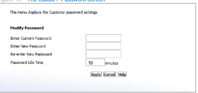
THE PASSWORD SCREEN
Use this screen to change the password with which you log in to the CGN2.
NOTE: If you forget your password, you will need to reset the CGN2 to its factory defaults.
Click Status > Password. The following screen displays.
SCDMA Mode This displays the Synchronous Code Division Multiple Access (SCDMA) mode of each channel on which the upstream signal is transmitted.
Signal Power (dBmV) This displays the transmitted power of the signal of each upstream data channel to which the CGN2 is connected, in dBmV (decibels above/below 1 millivolt).
Channel ID This displays the ID number of each channel on which the upstream signal is transmitted.
Cable Modem IP Information
IP Address This displays the CGN2’s WAN IP address. This IP address is automatically assigned to the CGN2 Subnet Mask This displays the CGN2’s WAN subnet mask.
Gateway IP This displays the IP address of the device to which the CGN2 is connected over the CABLE interface.
DHCP Lease Time This displays the time that elapses before your device’s IP address lease expires, and a new IP address is assigned to it by the DHCP server.
Figure 10: The Status > Password Screen
The following table describes the labels in this screen.
2.6
THE CAPABILITY SCREEN
Use this screen to enable or disable the CGN2’s residential gateway and Universal Plug n Play (UPnP) functions.
Table 10: The Status > Password Screen
Enter Current Password Enter the password with which you currently log into the CGN2
Enter New Password Enter and re-enter the password you want to use to log into the CGN2.
Re-enter New Password
Password Idle Time Enter the number of minutes of inactivity after which you should be automatically logged out of the CGN2. Once this period elapses, you will need to log in again.
Apply Click this to save your changes to the fields in this screen.
Cancel Click this to return the fields in this screen to their last-saved values without saving your changes.
Help Click this to see information about the fields in this screen.
Click Status > Capability. The following screen displays.
Figure 11: The Status > Capability Screen
The following table describes the labels in this screen.
Table 11: The Status > Capability Screen
Residential Gateway
function Select the checkbox to enable the CGN2’s residential gateway features, or deselect the checkbox to disable them.
UPnP Select the checkbox to enable the CGN2’s Universal Plug n Play features, or deselect the checkbox to disable them.
HNAP Select the checkbox to enable the CGN2’s Home Network Administration Protocol features, or deselect the checkbox to disable them.
USB Select the checkbox to enable the CGN2’s USB media sharing capability, or deselect the checkbox to disable them.
NOTE: This option is available to logged-in MSO users only.
When you select this checkbox and apply your changes, the CGN2 reboots. Once it has successfully rebooted, the WAN/LAN > Shared Media screen displays in the
cusadmin user interface.
Apply Click this to save your changes to the fields in this screen.
Cancel Click this to return the fields in this screen to their last-saved values without saving your changes.
Help Click this to see information about the fields in this screen.
3
WAN/LAN
This chapter describes the screens that display when you click WAN/LAN in the toolbar. It contains the following sections:
WAN/LAN Overview on page 45
The IP Screen on page 47
The Shared Media Screen on page 50
The Debug Screen on page 51
The Backup Screen on page 52
3.1
WAN/LAN OVERVIEW
This section describes some of the concepts related to the WAN/LAN screens.
3.1.1
WAN AND LAN
A Local Area Network (LAN) is a network of computers and other devices that usually occupies a small physical area (a single building, for example). Your CGN2’s LAN consists of all the computers and other networking devices connected to the LAN 1~4
ports. This is your private network (in routing mode - see Routing Mode on page 31).
The LAN is a separate network from the Wide Area Network (WAN). In the case of the CGN2, the WAN refers to all computers and other devices available on the cable connection.
By default, computers on the WAN cannot identify individual computers on the LAN; they can see only the CGN2. The CGN2 handles routing to and from individual computers on the LAN.
3.1.2
LAN IP ADDRESSES AND SUBNETS
IP addresses on the LAN are controlled either by the CGN2’s built-in DHCP server (see DHCP on page 29), or by you (when you manually assign IP addresses to your computers).
For more information about IP addresses and subnets in general, see IP Addresses and Subnets on page 27.
3.1.3
DNS AND DOMAIN SUFFIX
A domain is a location on a network, for instance example.com. On the Internet, domain names are mapped to the IP addresses to which they should refer by the Domain Name System. This allows you to enter “www.example.com” into your browser and reach the correct place on the Internet even if the IP address of the website’s server has changed.
Similarly, the CGN2 allows you to define a Domain Suffix to the LAN. When you enter the domain suffix into your browser, you can reach the CGN2 no matter what IP address it has on the LAN.
3.1.4
DEBUGGING (PING AND TRACEROUTE)
The CGN2 provides a couple of tools to allow you to perform network diagnostics on the LAN:
Ping: this tool allows you to enter an IP address and see if a computer (or other network device) responds with that address on the network. The name comes from the pulse that submarine SONAR emits when scanning for underwater objects, since the process is rather similar. You can use this tool to see if an IP address is in use, or to discover if a device (whose IP address you know) is working properly.
Traceroute: this tool allows you to see the route taken by data packets to get from the CGN2 to the destination you specify. You can use this tool to solve routing problems, or identify firewalls that may be blocking your access to a computer or service.
3.2
THE IP SCREEN
Use this screen to:
View information about the CGN2’s connection to the WAN
Enable or disable manual DNS assignment
Define DNS servers for manual DNS assignment
Configure the CGN2’s LAN IP address, subnet mask and domain suffix
Configure the CGN2’s internal DHCP server
Define how the CGN2 assigns IP addresses on the LAN
See information about the network devices connected to the CGN2 on the LAN. Click WAN/LAN > IP. The following screen displays.
Figure 12: The WAN/LAN > IP Screen
The following table describes the labels in this screen.
Table 12: The WAN/LAN > IP Screen
WAN Information
WAN Address This field displays the CGN2’s IP address on the WAN (Wide Area Network) interface.
Subnet Mask This field displays the CGN2’s WAN subnet mask.
Gateway Address This field displays the address of the device on the WAN to which the CGN2 is connected.
Assign DNS
Manually Select the checkbox to enable manual DNS server assignment, and enter the DNS servers that you want to use in the DNS Server fields below.
Deslect the checkbox to disable manual DNS server assignment. The CGN2 uses the DNS servers
assigned automatically when it receives an IP address over the WAN.
It is strongly recommended that you do not enable manual DNS server assignment unless you have good reason to do so.
DNS Server These fields display the Domain Name Servers that the CGN2 uses to resolve domain names into IP addresses. If you selected the Assign DNS Manually checkbox, enter the DNS servers that you want to use in these fields. Private LAN IP Setting
IP Address Use this field to define the IP address of the CGN2 on the LAN.
Subnet Mask Use this field to define the LAN subnet. Use dotted decimal notation (for example, 255.255.255.0).
Domain Suffix Use this field to define the domain that you can enter into a Web browser (instead of an IP address) to reach the CGN2 on the LAN.
It is suggested that you make a note of your device’s
Domain Suffix in case you ever need to access the CGN2’s GUI without knowledge of its IP address.
Private LAN DHCP Setting
Enable LAN DHCP Select this if you want the CGN2 to provide IP addresses to network devices on the LAN automatically.
Deselect this if you already have a DHCP server on your LAN, or if you wish to assign IP addresses to your
computers and other network devices manually. Lease Time Use this field to define the time after which the CGN2
renews the IP addresses of all the network devices connected to the CGN2 on the LAN (when DHCP is enabled).
DHCP Start IP Use this field to specify the IP address at which the CGN2 begins assigning IP addresses to devices on the LAN (when DHCP is enabled).
3.3
THE SHARED MEDIA SCREEN
Use this screen to manage and share data stored on devices connected to the CGN2’s USB port. The CGN2 provides one USB 2.0 host port, allowing you to plug in a USB flash disk for mounting and sharing through the LAN interfaces via the Samba protocol (network neighborhood).
NOTE: This screen is not available unless a logged-in MSO admin user previously enabled the USB option in the Status > Capability screen; see The
Capability Screen on page 42 for more information.
Click WAN/LAN > Shared Media. The following screen displays.
DHCP End IP Use this field to specify the IP address at which the CGN2 stops assigning IP addresses to devices on the LAN (when DHCP is enabled).
NOTE: Devices requesting IP addresses once the DHCP pool is exhausted are not assigned an IP address.
Connected Computers
Host Name This displays the name of each network device connected on the LAN.
IP Address This displays the IP address of each network device connected on the LAN.
MAC Address This displays the Media Access Control (MAC) address of each network device connected on the LAN.
Type This displays whether the device’s IP address was assigned by DHCP (DHCP-IP), or self-assigned.
Interface This displays whether the device is connected on the LAN (Ethernet) or the WLAN (Wireless(x), where x denotes the wireless mode; b, g or n).
Apply Click this to save your changes to the fields in this screen. Cancel Click this to return the fields in this screen to their
last-saved values without saving your changes.
Help Click this to see information about the fields in this screen.
Figure 13: The WAN/LAN > Shared Media Screen
The following table describes the labels in this screen.
3.4
THE DEBUG SCREEN
Use this screen to perform ping and traceroute tests on IP addresses or URLs.
Table 13: The WAN/LAN > Shared Media Screen
Group ID Specify the name of the Network Neighborhood
workgroup whose users may access the shared media on the USB device.
No. This field displays the index number of the connected USB device.
When no USB device is connected, no number displays in this column.
Name This field displays the identifying name of the connected USB device.
When no USB device is connected, no name displays in this column.
When a USB device is connected, click its Name to view the files on the device. These files are shared with the relevant user group (defined in the Group ID
field).
Apply Click this to save your changes to the fields in this screen.
Refresh Click this to reload the information in this screen. Do this if you connect or disconnect a device from the USB port and the information in this screen does not update automatically.
Help Click this to see information about the fields in this screen.
Click WAN/LAN > Debug. The following screen displays.
Figure 14: The WAN/LAN > Debug Screen
The following table describes the labels in this screen.
3.5
THE BACKUP SCREEN
Use this screen to back up your CGN2’s settings to your computer, to load settings from a backup you created earlier, to reboot your CGN2, or to return it to its factory default settings.
Click WAN/LAN > Backup. The following screen displays.
Table 14: The WAN/LAN > Debug Screen
IP/URL Enter the IP address or URL that you want to test. Method Select the type of test that you want to run on the IP/
URL that you specified. Run Click this to perform the test.
Help Click this to see information about the fields in this screen.
Figure 15: The WAN/LAN > Backup Screen
The following table describes the labels in this screen.
Table 15: The LAN > Backup Screen
Backup/Restore Setting Backup Settings
Locally Click this to create a backup of all your CGN2’s settings on your computer. Restore Settings
Locally Use these fields to return your CGN2’s settings to those specified in a backup that you created earlier. Click Choose File to select a backup, then click
Restore to return your CGN2’s settings to those specified in the backup.
Reboot/Factory Reset
Reboot Click Reboot to restart your CGN2.
Factory Reset Click Factory to return your CGN2 to its factory default settings.
NOTE: When you do this, all your user-configured settings are lost, and cannot be retrieved.
Help Click this to see information about the fields in this screen.
4
FIREWALL
This chapter describes the screens that display when you click Firewall in the toolbar. It contains the following sections:
Firewall Overview on page 54
The Firewall Options Screen on page 56
The Filter Setting Screen on page 57
The Forwarding Screen on page 65
The Port Triggering Screen on page 69
The DMZ Screen on page 72
4.1
FIREWALL OVERVIEW
This section describes some of the concepts related to the Firewall screens.
4.1.1
FIREWALL
The term “firewall” comes from a construction technique designed to prevent the spread of fire from one room to another. Similarly, your CGN2’s firewall prevents intrusion attempts and other undesirable activity originating from the WAN, keeping the computers on your LAN safe. You can also use filtering techniques to specify the computers and other devices you want to allow on the LAN, and prevent certain traffic from going from the LAN to the WAN.
4.1.2
INTRUSION DETECTION SYSTEM
An intrusion detection system monitors network activity, looking for policy violations, and malicious or suspicious activity. The CGN2’s intrusion detection system logs all such activity to the Firewall > Local Logs screen.
4.1.3
PING
The CGN2 allows you to use the ping utility on the LAN (in the WAN/LAN > Debug
screen) and also on the WAN (in the Firewall > Firewall Options screen). For more information, see Debugging (Ping and Traceroute) on page 46.
4.1.4
MAC FILTERING
Every networking device has a unique Media Access Control (MAC) address that identifies it on the network. When you enable MAC address filtering on the CGN2’s firewall, you can set up a list of MAC addresses, and then specify whether you want to:
Deny the devices on the list access to the CGN2 and the network (in which case all other devices can access the network)
or
Allow the devices on the list to access the network (in which case no other devices can access the network)
4.1.5
IP FILTERING
IP filtering allows you to prevent computers on the LAN from sending certain types of data to the WAN. You can use this to prevent unwanted outgoing communications. Specify the IP address of the computer on the LAN from which you want to prevent communications, and specify the port range of the communications you want to prevent. The CGN2 discards outgoing data packets that match the criteria you specified.
4.1.6
PORT FORWARDING
Port forwarding allows a computer on your LAN to receive specific communications from the WAN. Typically, this is used to allow certain applications (such as gaming) through the firewall, for a specific computer on the LAN. Port forwarding is also commonly used for running a public HTTP server from a private network.
You can set up a port forwarding rule for each application for which you want to open ports in the firewall. When the CGN2 receives incoming traffic from the WAN with a destination port that matches a port forwarding rule, it forwards the traffic to the LAN IP address and port number specified in the port forwarding rule.
NOTE: For information on the ports you need to open for a particular application, consult that application’s documentation.
4.1.7
PORT TRIGGERING
Port triggering is a means of automating port forwarding. The CGN2 scans outgoing traffic (from the LAN to the WAN) to see if any of the traffic’s destination ports match those specified in the port triggering rules you configure. If any of the ports match, the CGN2 automatically opens the incoming ports specified in the rule, in anticipation of incoming traffic.
4.1.8
DMZ
In networking, the De-Militarized Zone (DMZ) is a part of your LAN that has been isolated from the rest of the LAN, and opened up to the WAN. The term comes from the military designation for a piece of territory, usually located between two opposing forces, that is isolated from both and occupied by neither.
4.2
THE FIREWALL OPTIONS SCREEN
Use this screen to turn firewall features on or off. You can enable or disable the CGN2’s intrusion detection system, and allow or prevent responses to ICMP requests from the WAN.
Figure 16: The Firewall > Firewall Options Screen
The following table describes the labels in this screen.
4.3
THE FILTER SETTING SCREEN
Use this screen to configure Media Access Control (MAC) address filtering on the LAN, and to configure IP filtering.
Table 16: The Firewall > Firewall Options Screen
Firewall Select this to turn the firewall on.
Deselect this to turn the firewall off.
NOTE: It is strongly recommended that you enable the CGN2's firewall unless LAN protection is
provided by another device or software.
Intrusion Detection
System Select this to turn the intrusion detection system off.Deselect this to turn the intrusion detection system on.
Ping on WAN Interface Select this to prevent responses to ICMP requests originating from the WAN.
Select this to allow responses to ICMP requests originating from the WAN.
Apply Click this to save your changes to the fields in this screen.
Cancel Click this to return the fields in this screen to their last-saved values without saving your changes.
Help Click this to see information about the fields in this screen.
NOTE: To configure MAC address filtering on the wireless network, see The Access Control Screen on page 93.
You can set the CGN2 to allow only certain devices to access the CGN2 and the network, or to deny certain devices access.
NOTE: To see a list of all the computers connected to the CGN2 on the LAN, click the Connected Computers button in the Firewall > IP Filtering,
Forwarding, Port Triggering or Firewall Options screens.
You can turn IP filtering on or off, and configure new and existing IP filtering rules. Click Firewall > Filter Setting. The following screen displays.
The following table describes the labels in this screen.
Table 17: The Firewall > Filter Setting Screen
MAC Filter Options
MAC Filter Options Use this field to control whether the CGN2 performs MAC filtering.
Select Allow-All to turn MAC filtering off. All devices may access the CGN2 and the network.
Select Allow to permit only devices with the MAC addresses you set up in the Allow Table to access the CGN2 and the network. All other devices are denied access.
Select Deny to permit all devices except those with the MAC addresses you set up in the Deny Table to access the CGN2 and the network. The specified devices are denied access.
Allow Table (up to 16 Items)
# This displays the index number assigned to the permitted device.
Device Name This displays the name you gave to the permitted device. MAC Address This displays the MAC address of the permitted device. Delete Select a permitted device’s radio button ( ) and click this
to remove the device from the list. The device may no longer access the CGN2 and the network.
NOTE: Make sure you do not delete your management computer from the list; if you do so, you will need to log back in from another computer, or reset the CGN2.
Deny Table (up to 16 Items)
# This displays the index number assigned to the denied device.
Device Name This displays the name you gave to the denied device. MAC Address This displays the MAC address of the denied device. Delete Select a denied device’s radio button ( ) and click this to
remove the device from the list. The device may now access the CGN2 and the network.
Device Name This displays the name of each network device that has connected to the CGN2 on the LAN. To change the name assigned to a device, edit it in the relevant field.
MAC Address This displays the MAC address of each network device that has connected to the CGN2 on the LAN.
Type Use this field to specify the list to which you want to add the device.
Select Allow to add the device to the Allow Table.
Select Deny to add the device to the Deny Table. Manually-Added LAN Devices
Device Name Enter the name to associate with a network device that you want to permit or deny access to the CGN2 and the network.
NOTE: This name is arbitrary, and does not affect functionality in any way.
MAC Address Specify the MAC address of the network device that you want to permit or deny access to the CGN2 and the network.
Type Use this field to specify the list to which you want to add the device.
Select Allow to add the device to the Allow Table.
Select Deny to add the device to the Deny Table. Add Click this to add the device to the list you specified. Cancel Click this to clear the Manually-Added LAN Devices
fields.
Apply Click this to save your changes to the fields in the Mac Filter tables.
Cancel Click this to return the fields in the Mac Filter tables to their last-saved values without saving your changes. Help Click this to see information about the fields in this screen. IP Filtering Options
All IP Filtering Rules Use this to turn IP filtering on or off.
Deselect the checkbox to enable IP filtering.
Select the checkbox to disable IP filtering (default).
NOTE: You can add, edit or delete IP filtering rules only when this checkbox is deselected.
Select Select an IP filtering rule’s radio button ( ) before clicking Edit or Delete.
# This displays the arbitrary identification number assigned to the IP filtering rule.
Application Name This displays the arbitrary name you assigned to the rule when you create it.
Port Range This displays the start and end values of the ports to which communications from the specified IP addresses is not permitted.
Protocol This displays the type of communications that are not permitted:
TCP displays if communications via the Transmission Control Protocol are not permitted.
UDP displays if communications via the User Datagram Protocol are not permitted.
TCP/UDP displays if communications via the
Transmission Control Protocol and the User Datagram Protocol are not permitted.
IP Address Range This displays the start and end IP address from which communications to the specified ports are not permitted. Enable Use this field to turn each IP filtering rule on or off.
Select this checkbox to enable the IP filtering rule.
Deselect this checkbox to disable the IP filtering rule. Add New Click this to define a new IP filtering rule. See Adding or Editing an IP Filtering Rule on page 63 for information on the screen that displays.
Edit Select an IP filtering rule’s radio button ( ) and click this to make changes to the rule. See Adding or Editing an IP Filtering Rule on page 63 for information on the screen