DATA SHEET RC18x2HP-IPM
1
Product Description
The RC18x2HP-IPM is a series of high power sub-1 GHz
programmable ultra-low power module for RIIM (Radiocrafts Industrial IP Mesh). It is based on the open radio standard IEEE802.15.4 g/e, and implements IPv6 internet addressing with support for UDP, CoAP and
encryption. The RC18x2HP-IPM is used to implement all the nodes in the network including leaf nodes, wireless router nodes and root-node/border routers.
The module incudes ICI, the intelligent C-programmable I/O, along with all neccesary drivers and the operating system. ICI allows the user to program his own intelligent sensor/actuator inteface, or any other applciation with minimal effort. The programming capability of the module makes it possible to interface to any sensor/actuator or combination of sensors/actuators.Thereby, removing the need for an additional MCU to reduce overall cost and power consumption.
2
Applications
• Coin cell battery systems
• IIoT applications
• Smart Sensor Technologies
• Energy Management and Sustainability
• Green House Monitoring and control
• Elderly Care
• Fire Detection
• Home Security
• Indoor Air Quality Monitoring
• Industrial Temperature Control
• Medical Climate Control
• Predictive Maintenance
• Tank Level/Flow Monitoring
• Facilities and Infrastructure Management
• Radiation and Leak Detection
• Irrigation monitor and control
3
Features
• Internet interoperability via IPv6 addressing, UDP packet transmission, DTLS encryption and CoAP protocol.
• Multi-hop mesh technology.
• Self building and self healing network.
• Over The Air (OTA) updates
• Very high node count mesh
• Long RF range, several hundred meter LOS
• Many electrical interfaces: 9 programmable GPIOs, I2C bus, SPI bus, UART and 2 ADC inputs
• Intelligent C-Programmable I/O (ICI) easy to use C-based SDK to directly inteface any sensor/actuator
• Ultra-low power for coin cell battery or energy harvesting
• Pre-certified radio
• Based on open radio standards IEEE 802.15.4 g/e
• Frequency hopping via TSCH (6TiSCH) (Availeble for RIIM-SDK 1.20.0)
DATA SHEET RC18x2HP-IPM
4
Quick Reference Data (typical at 3.6V, 868 MHz, 50 kb/s)
Parameter RC1882HPCF-IPM RC1892HPCF-IPM Unit
Frequency band 865-870 902-928 MHz
Max output power 271 27 dBm
Sensitivity (BER 1%) @50kb/s -111 -111 dBm
Supply voltage 2.3 - 3.6 2.3 - 3.6 V
Current consumption, RX/TX 12.5 / 350 12.5 / 350 mA
Current consumption, Shutdown 2 2 uA
User application flash memory 32 32 kB
User application RAM 8 8 kB
Internal SPI Flash 1024 1024 kB
DATA SHEET RC18x2HP-IPM
5
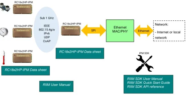
RIIM overview
The RIIM network consists of these key elements - The RIIM SDK
o Software development kit with application frameworks and tools for creating and uploading end applications to the RC18x2HP-IPM
- The IPM module
o The IPM module can be configured as root, router or leaf node.
▪ As a root node it acts as the base of the mesh network. It can connect to an external network via ethernet or custom user application on other interfaces such as UART
▪ As a router node, it will be able to transport packets in the RIIM mesh network
▪ As a leaf node, it is not able to transport packets to other nodes except its parent. This mode uses the least amount of energy.
o All modes supports customer ICI applications and external connections. Applications use the same RIIM Software Development Kit (SDK) for all node types.
Below is an illustration of the different elements and the documentation available
Figure 1. RIIM network – system and documentation overview
Ethernet MAC/PHY SPI Ethernet RC1880-GPR RC18x2HP-IPM RC1880-GPR RC18x2HP-IPM RC1880-GPR RC18x2HP-IPM
RC18x2HP-IPM Data sheet
IPM SDK
RIIM SDK User Manual RIIM SDK Quick Start Guide RIIM SDK API reference RC18x2HP-IPM Data sheet
Sub 1 GHz IEEE 802.15.4g/e IPv6 UDP CoAP RC1880-GPR RC18x2HP-IPM Network: - Internet or local network
DATA SHEET RC18x2HP-IPM
6
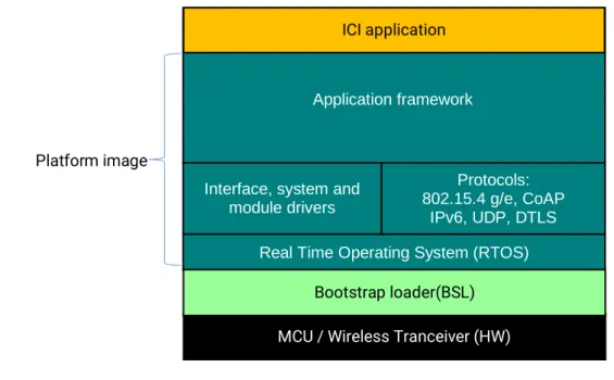
Firmware structure
The RIIM module’s program memory is divided in 3 different segments. - The bootloader
- The platform image - Application image
Figure 2. System overview
The bootloader is preloaded from Radiocrafts. It allows the user to upload new platform images or unique
application images. The bootloader also allows the user to program unique encryption keys into the device. These keys are not possible to read out. The bootloader uses the standard UART port and operates at 115200 baud. Note that the bootloader also leaves all GPIO in tristate mode at power up. If a specific application requires controlled high or low level during start up, an external pull-up/pull-down is mandatory.
The platform image is the main firmware part and includes, the operating system, network stacks, drivers and application frameworks. This firmware image is preloaded from Radiocrafts and newer revisions will be made available from Radiocrafts as an encrypted image. When downloading a new platform image through the bootloader, the image will be decrypted internally in the module.
The application code space has available 32 kB of flash space and 8 kB of RAM.
MCU / Wireless Tranceiver (HW) Real Time Operating System (RTOS) Interface, system and
module drivers Protocols: 802.15.4 g/e, CoAP IPv6, UDP, DTLS Application framework ICI application Bootstrap loader(BSL) Platform image
DATA SHEET RC18x2HP-IPM
7
Software Development Kit (SDK)
RC18x2HP-IPM allows each user to write his own application with minimal time and effort. This is accomplished through an SDK, which consists of 3 key blocks
Figure 3. Software Development Kit
The application framework acts as the skeletal support to build an application. It abstracts the resources such that the developer does not need to dive into all the details of the processor, network stack or operating system. This consept is referred to as Intelligent C-programmable I/O (ICI).
The application framework comes with a ready-made base application that the user can tailor to his needs. The tailoring is accomplished through defining events and writing the event handlers. The base application reduces the workload on the user and reduces test and validation time for each new application.
For the developer the main interaction with the application framework is through an intuitive API, describing how the user can interface with the radio/network and high level drivers.
See the document RIIM SDK User Manual and RIIM API Reference for details.
In each event handler, the user can send and receive data through the different interfaces, access memory, invoke network function or even do complex data algorithms and data processing.
Application builder is a set of free tools to generate the application image based on user's application code. Bootloader utlity is a free tool that allows secure uploading of application images to the module. It also allows writing of encryption keys in the module during production.
More details on the application builder and the bootloader utility is given in RIIM SDK User Manual. Application builder
Bootloader utility Application Framework
DATA SHEET RC18x2HP-IPM
8
Intelligent C-programmable I/O (ICI)
The ICI application is written in high-level C-language, using a powerful API that is available in the SDK. The API removes the need for the developer to understand the underlying architecture and resources in the module. In its simplest form, the ICI application is just configuring the radio network, the modules hardware interfaces and defining when to read and write to those interfaces. This can typically be done with less than 100 lines of code and within a few hours. Examples included in SDK are normally a good starting point.
The ICI application also has the capability of including complex data processing and advanced features, such as averaging and threshold detection using one or many sensors in combination or to create complex sensor interfaces. The flash space available for the ICI application is 32 kB
See the RIIM SDK User Manual, RIIM SDK API Reference and the RIIM SDK Quick Start documents for more information.
Example : ICI code
#include "RIIM_UAPI.h"
const uint8_t IP_Addr[4]={0,0,0,0};
const uint8_t IP_Mask[4]={255,255,255,0};
const uint8_t IP_GW[4]={192,168,150,1};
RIIM_SETUP() {
Util.printf("Starting RIIM Root Node\n");
// Setup network and RF
Network.startBorderRouter(NULL,IP_Addr,IP_Mask,IP_GW);
return UAPI_OK;
DATA SHEET RC18x2HP-IPM
9
Pin Assignment
10
Pin Description
Pin no Pin name Description
1 GND System ground
2 CTS UART flow control
3 RTS UART flow control
4 BSL Enable boot strap loader
5 TXD Configurable I/O pin
6 RXD Configurable I/O pin
7 GND System ground
8 I2C SDA I2C SDA, internal 4.7k pullup
9 I2C SCL I2C SCL, internal 4.7k pullup
10 ADC1 Analog input
11 ADC2 Analog input
12 TMSC JTAG interface
13 TCKC JTAG interface
14 TDO JTAG interface
42 41 40 39 38 37 36 35 34 33 32 31 30 29 1 28 2 27 3 26 4 25 5 24 6 23 7 22 8 9 10 11 12 13 14 15 16 17 18 19 20 21 GND CTS RTS BSL TXD RXD GND GND VCC Reset_N RX/TX GND RF GND G P IO 0 G P IO 1 G P IO 2 G P IO 3 G P IO 4 G P IO 5 G P IO 6 G P IO 7 G P IO 8 S P I_ C LK S P I_ S I S P I_ S O R ES V. R ES V. I2 C _S D A I2 C _S CL A D C 1 A D C 2 T M S C T C K C T D O T D I S EN S _1 S EN S _2 S EN S _3 P A _C T R (N .C ) P A _C T R (N .C ) P A _C T R (N .C )
DATA SHEET RC18x2HP-IPM
15 TDI JTAG interface
16 SENS_1 Reserved for future use
17 SENS_2 Reserved for future use
18 SENS_3 Reserved for future use
19 PA_CTR Internally used signal to control PA. Do not connect. 20 PA_CTR Internally used signal to control PA. Do not connect. 21 PA_CTR Internally used signal to control PA. Do not connect.
22 GND System ground
23 RF RF I/O connection to antenna
24 GND System ground
25 RX/TX Not connected
26 RESET_N Reset (Active low)
27 VCC Supply voltage
28 GND System ground
29 RESV. Reserved for future use
30 SPI_CS_I SPI CS for internal flash, Do not connect
31 SPI_SO SPI bus
32 SPI_SI SPI bus
33 SPI_CLK SPI bus
34 GPIO_8
General purpose I/O pin. Pin is tristated by module during bootloading. Add pull-up if used as SPI chip select(CS) for external SPI devices.
35 GPIO_7 36 GPIO_6 37 GPIO_5 38 GPIO_4 39 GPIO_3 40 GPIO_2 41 GPIO_1 42 GPIO_0
Note 1: Pins 8 and 9 are suggested as I2C interface. They can be configured otherwise, but are connected to an optional internal EEPROM with I2C address = 000. It is recommended to leave these pins as I2C. Sensors and actuators or any other I2C device can be connected to these pins and accessed from the module.
11
ADC Parameters
Parameter Value Description
# bits 12 Bits
Input impedance >1 Mohm
Internal reference 4.3 V
External reference voltage VDD V
ENOB Effective number of bits 10.0 Internal
reference, 200ksamples/s 9.6 kHz tone
THD Total harmonic distortion -65 dB
SINAD and SNDR Signal-to-noise and distortion ratio
62 dB
DATA SHEET RC18x2HP-IPM
12
SPI Parameters
Parameter Value Description
SPI clock rate max 12 MHz
SPI mode Master
Modes supported 0,1,2 and 3
SPI chip select SW chip select (GPIO 0-8) Note that when using an SPI device the CS must have external pull-up, since the bootloader uses SPI BUS vs internal flash
13
I2C Parameters
Parameter Value Description
I2C clock rate 100/400 kHz
Pull up resistor 4.7 kΩ Embedded in module
Clock stretching support Yes
14
GPIO parameters
Parameter Value Description
Number of GPIO 9
Pull up resistor 25 kΩ Typical
Pull down resistor 85 kΩ Typical
Source/sink current 2 mA Max
VIH 0.8*VCC Minimum input voltage to be
reliable read as high
VIL 0.2*VCC Maximum input voltage to
be reliable read as low
Status during bootloading Tri-state
15
Timers
Parameter Value Description
Resolution 7 ms User can set a timer with 1
ms resolution, but actual resolution the time the event is handled is 7 ms.
Max length 2^32ms = ~49 days millisecond
days
Timer types One-shot
DATA SHEET RC18x2HP-IPM
Current consumption
Current consumption on the module will depend on which role it has in the network and what function it is setup to perform.
Role Typical default
current consumption Single channel CSMA TSCH / Frequency hopping Sleeping mesh TSCH Border router 12,5 mA 12,5 mA 12,5 mA Mesh Router 12,5 mA 1.4 mA (TBC) 0.25 mA (TBC)
Sleeping leaf node 25 µA (TBC)
These number include the network maintenance functions, but actual current consumption depends on the application running on the node. See the RIIM User Manual for detailed examples on how to estimate current consumption.
16
Regulatory Compliance Information
The use of RF frequencies and maximum allowed transmitted RF power is limited by national regulations.
The RC1882HP has been have been designed to comply with regulations (RED directive 2014/53/EU in Europe) and GSR 564 in India.
The RC1892HP has been designed to comply to FCC/IC requiremen for US/Canada t and ACMA requirement in Australia
17
Timing, Latency and Throughput
See the RIIM User Manual for details and examples on how to calculate these for real world applications.
Parameter Value Description
Single channel CSMA TSCH /Frequency hopping
On-air time 160 µs / Byte 160 µs / Byte Time for transmitting 1
byte at 50 kbps
Neighbor acknowledgement < 1 ms < 1 ms
Routing processing time per hop Typ. 45 ms Average 425 ms2
Node response time Typ. 40 ms Average 420 ms
As with all radio these are not 100% predictable. For instance, the radio includes listen-before-talk to increase robustness and reduce interference. Also packet loss and the automatic retransmission will cause an extra delay.
DATA SHEET RC18x2HP-IPM
18
RF channels
The RF channels in are configured through the ICI application and follow IEEE802.15.4g standard for MR-FSK operating mode #1.
For RC1882HPCF if channel 32 shall be used as is allows for up to 27 dBm output power.
The channels numbering for 863-870 MHz band is given below are given below. For all other channels than channel 32, output power must be adjusted down for compliance to RED directive in Europe.
Table 1 Channels in 863-870 MHz band
Channel Center frequency [MHz]
0 863.125 1 863.325 2 863.525 3 863.725 4 863.925 5 864.125 6 864.325 7 864.525 8 864.725 9 864.925 10 865.125 11 865.325 12 865.525 13 865.725 14 865.925 15 866.125 16 866.325 17 866.525 18 866.725 19 866.925 20 867.125 21 867.325 22 867.525 23 867.725 24 867.925 25 868.125 26 868.325 27 868.525 28 868.725 29 868.925 30 869.125 31 869.325 32 869.525 33 869.725
For the 902-928 MHz frequency band IEEE 802.15.4g defines 129 channel 902.2 + 0.2*N MHz
But to comply to FCC regulation frequency hopping (TSCH) must be used and hopping must be done at minimum 50 channels.
DATA SHEET RC18x2HP-IPM
When using TSCH at 915 MHz 50 channels are used the range 904.2 MHz -914.0 MHz with 200 kHz raster.19
Mechanical Drawing
20
Mechanical Dimensions
The module size is 12.7 x 25.4 x 3.7 mm.
21
Carrier Tape and Reel Specification
Carrier tape and reel is in accordance with EIA Specification 481.
Tape width Component pitch
Hole pitch Reel diameter
Units per reel
DATA SHEET RC18x2HP-IPM
22
PCB Layout Recommendations
The recommended layout pads for the module are shown in the figure below.
The circle in upper left corner is an orientation mark only, and should not be a part of the copper pattern.
Dimention Length [mm] (mil) Comment
A 25.4 (1000) Length of module
B 12.7 (500) Width of module
C 0.79 (31) Module edge vs centre of pad (Valid for all pads)
D 1.27 (50) Pad to pad distance
E 2.54 (100) Modul edge to pad (centre)
F 3.81 (150) Modul edge to pad (centre)
G 0.9 (35.4) Length of pad/recommend footprint pad
H 0.7 (27.6) Width of pad/recommend footprint pad
Recommended pad design is shown below.
The recommended footprint for solder soldering is a one-to-one mapping between the LGA pad on module and the footprint.
For prototype build a solder hot plate is recommended. If the prototype is soldered manually by soldering iron, it is recommend to extend the pads of the footprint out from the module to make is accessible for a soldering iron.
A B C D E E E F G H Pin 1
DATA SHEET RC18x2HP-IPM
A PCB with two or more layers and with a solid ground plane in one of the inner- or bottom layer(s) isrecommended. All GND-pins of the module shall be connected to this ground plane with vias with shortest possible routing, one via per GND-pin.
Routing or vias under the module is not recommended as per IPC-recommendation. If any routing or vias is
required under the module, the routing and vias must be covered with solder resist to prevent short circuiting of the test pads. It is recommended that vias are tented.
Reserved pins should be soldered to the pads, but the pads must be left floating electrically (no connection).
Note that Radiocrafts technical support team is available for free-of-charge schematic- and layout review of your design.
23
Soldering Profile Recommendation
JEDEC standard IPC/JEDEC J-STD-020D.1 (page 7 and 8), Pb-Free Assembly is recommended.
The standard requires that the heat dissipated in the "surroundings" on the PCB is taken into account. The peak temperature should be adjusted so that it is within the window specified in the standard for the actual
motherboard.
Aperture for paste stencil is normally areal-reduced by 20-35%, please consult your production facility for best experience aperture reduction. Nominal stencil thickness of 0.1-0.12 mm recommended.
DATA SHEET RC18x2HP-IPM
24
Absolute Maximum Ratings
Parameter Min Max Unit
Caution ! ESD sensitive device. Precaution should be used when handling the device in order to prevent permanent damage.
Supply voltage, VCC -0.3 4.1 V
Voltage on any pin -0.3 VCC + 0.3
(max 4.1) V
Input RF level 10 dBm
Storage temperature -40 150 C
Operating temperature -30 85 C
Under no circumstances the absolute maximum ratings given above should be violated. Stress exceeding one or more of the limiting values may cause permanent damage to the device.
25
Electrical Specifications
T=25C, VCC = 3.3V, 868 MHz, 50 ohm if nothing else stated.
Parameter Min Typ. Max Unit Condition / Note
Operating frequency 865 928 MHz
Input/output impedance 50 Ohm
Data rate 50 kbit/s
Frequency stability +/- 10 +/-15 +20/-26 ppm ppm ppm Initially Temperature drift -30°-85° Temperature drift -40°-85° Other stability option available on request
Transmit power 10 27 dBm Programmable from firmware
Harmonics 2nd harmonic 3rd harmonic -44 -43 dBm dBm
@ max output power Spurious emission, TX, 868 MHz 30 – 1000 MHz 30 – 1000 MHz 1-12.75 GHz -54 -36 -30 dBm dBm dBm EN 300 220 restricted band EN 300 220 un-restricted band
Sensitivity - 111 dBm BER = 1%, 50 kbps 2 FSK, IEEE
802.15.4g mandatory settings
Saturation 0 dBm
Spurious emission, RX
1-12.75 GHz -59 dBm
Complies with EN 300 220 CRF47 Part 15 and ARIB STD-T66
Supply voltage
Recommended operating voltage 2.3 3.6 V
Current consumption, RX 12.5 mA VCC = 3.6V
Current consumption, TX 350 mA Output power 27 dBm,
VCC = 3.6V Current consumption, Deep Sleep Active sleep 1.1 25 uA uA
Leaf nodes only Node maintaing network connection. 27 dBm output power
RAM memory
RAM available for ICI application
88 8
kB kB SoC internal Flash memory
Flash available for ICI application
352 32
kB kB
SPI Flash memory 1024 kB
DATA SHEET RC18x2HP-IPM
Parameter Min Typ. Max Unit Condition / Note
MCU low frequency crystal 32.768 kHz Optional
Antenna VSWR <2:1 3:1
26
Ordering number
Ordering number Definition
RC1882HPCF-IPM 865-870 MHz, EU/India variant
Standard product Includes
-C 32 kHz RTC crystal -F 1024 kB SPI flash for OTA RC1892HPCF-IPM 902.928 MHz, US/CAN/AU variant
*other variant available for turn-key projects
27
Product Status and Definitions
Current Status
Data Sheet Identification Product Status Definition
Advance Information Planned or under development
This data sheet contains the design specifications for product
development. Specifications may change in any manner without notice.
X
Preliminary Engineering
Samples and First Production
This data sheet contains preliminary data, and supplementary data will be published at a later date. Radiocrafts reserves the right to make changes at any time without notice in order to improve design and supply the best possible product.
No Identification Noted Full Production This data sheet contains final
specifications. Radiocrafts reserves the right to make changes at any time without notice in order to improve design and supply the best possible product.
Not recommended for new designs
Last time buy available
Product close to end of lifetime
Obsolete Not in Production
Optionally accepting order with Minimum Order Quantity
This data sheet contains
specifications on a product that has been discontinued by Radiocrafts. The data sheet is printed for reference information only.
DATA SHEET RC18x2HP-IPM
Disclaimer
Radiocrafts AS believes the information contained herein is correct and accurate at the time of this printing. However, Radiocrafts AS reserves the right to make changes to this product without notice. Radiocrafts AS does not assume any responsibility for the use of the described product; neither does it convey any license under its patent rights, or the rights of others. The latest updates are available at the Radiocrafts website or by contacting Radiocrafts directly.
As far as possible, major changes of product specifications and functionality, will be stated in product specific Errata Notes published at the Radiocrafts website. Customers are encouraged to check regularly for the most recent updates on products and support tools.
Trademarks
All trademarks, registered trademarks and product names are the sole property of their respective owners.
Life Support Policy
This Radiocrafts product is not designed for use in life support appliances, devices, or other systems where malfunction can reasonably be expected to result in significant personal injury to the user, or as a critical
component in any life support device or system whose failure to perform can be reasonably expected to cause the failure of the life support device or system, or to affect its safety or effectiveness. Radiocrafts AS customers using or selling these products for use in such applications do so at their own risk and agree to fully indemnify
Radiocrafts AS for any damages resulting from any improper use or sale.
Radiocrafts Webpage
For more info go to our web page : https://radiocrafts.com/
There you can find Knowledge base and Document Library that includes Application notes, Whitepapers, Declaration of Conformity, User Manuals, Data Sheet and more.
Contact Information
Web site: www.radiocrafts.com Email: radiocrafts@radiocrafts.com Address: Radiocrafts AS Sandakerveien 64 NO-0484 OSLO NORWAY Tel: +47 4000 5195 Fax: +47 22 71 29 15 E-mail: sales@radiocrafts.com
![Table 1 Channels in 863-870 MHz band Channel Center frequency [MHz]](https://thumb-us.123doks.com/thumbv2/123dok_us/9667711.2454832/11.892.277.617.336.1061/table-channels-mhz-band-channel-center-frequency-mhz.webp)
