Framework for
Automatic Fare Collection
Systems
tion series should be addresses to the publisher:
Limits of Liability and Disclaimer of Warranty
The author and publisher of this White Paper have used their best efforts in preparing the material presented and make no warranty with regard to its contents.
Price: CHF xxx.xx Edition: March 1999 Printed in Switzerland ASCOM Autelca AG Worbstrasse 201 CH-3073 Gümligen - Bern Phone Fax Email +41 31 999 61 11 +41 31 999 63 48 [email protected]
Contents
Introduction ... 5
Functions in a Fare Collection System on the user level ... 7
Steps in the process ... 7
Select... 8 Pay... 9 Produce ... 9 Deliver ... 10 Check ... 10 Accounting ... 10 Service ... 11
Common elements on the system level... 12
Presentation... 12
Communication ... 12
Data handling ... 13
Processes ... 13
Ticket Vending Framework... 15
Layers ... 15
System architecture ... 17
Conventions in the ACFW ... 17
System design... 19
Services ... 19
Basic abstractions... 20
ACFW components ... 21
Generic Control Process ... 23
General definitions ... 23
Special features... 24
Output command ... 24
Layout concept ... 26
Aims of the layout concept ... 26
Engineering a layout ... 27
Output to printer or display ... 28
Layout management ... 29
Process structure ... 30
Device handling ... 31
4
Structure of media description ... 34
Device Communication Framework ... 37
VendoBus ... 37 asCAN ASIC ... 38 VendoBus protocol... 38 EasyPlug... 39 Glossary... 41 Standards ... 45
Introduction
Enhancing the efficiency of fare collection is a permanent challenge of public transport authorities and operators.
In ‘the good old days’ the fare collection system gave work to a number of different persons performing individual tasks: the salesman, the cashier, the ticket inspector on the train etc. Gradually these tasks were handled by fewer people and eventually the handling of standard tickets became completely automatic.
Automatic Fare Collection Systems (AFCS) started with ticket vending machines with a fixed repertoire of pre-printed tickets. Further steps introduced printing on the fly based on the user selection, enlarging the repertoire ticket types with paper selection etc.
Modern ticket vending machines comprise for example flexible product selection, various payment methods or different media. They were, however, individually designed and manufactured for a particular oper-ator. Although the tasks to be performed by the machines are the same in principle, mechanical and electrical components could not be designed flexible enough to serve the demands of various operators with a single design.
Further development moved from mechanical and electrical systems to software driven systems, which provide great flexibility in the set-up and a rich set of functions to serve the operator needs. These systems, however, are still very demanding in the engineering phase. The sys-tems for each operator are developed individually and the operator can not modify or expand the systems.
The framework described in this White Paper gives both the manufac-turer and the operator of the Automatic Fare Collection System full flexibility in design and manufacturing as well as capability for expan-sion and modification to cope with the necessary changes in services to the user.
Functions in a Fare Collection System
on the user level
To understand the solutions provided by the framework for an Auto-matic Fare Collection System the tasks to be performed must be known. This section provides detailed information about the needed functions in an Automatic Fare Collection System.
Steps in the process
Both the ‘sales shop’ system and a modern completely automatic fare collection system must provide the same functions to the user of the transport system and hence comprise the same steps in the complete process (see figure 1):Idle The Fare Collection System waits for a user interaction. Select The user selects a product from the offer of the
trans-port authority.
Pay The user pays with money or other means.
Produce The permission to consume the product is produced. Deliver The permission is handed out to the user.
Check In a closed ‘transport system’ the use of the permission is checked.
Consume The user consumes the permission to be transported.
Figure 1: AFCW Overview Idle Select Deliver Pay Produce Accounting + Statistics Check Consume Service
8
Each of these steps in the fare collection process is ruled by various means and restricted by more or less dynamic conditions, such as avail-ability of products or method of payment. In the complete system addi-tional roles are defined, such as
Accounting The implied financial transaction is handled together with information about the product.
Service Maintenance of the hardware- and software in the sys-tem, updating of the data needed to perform the tasks. A systems management must also be present which defines the various roles and functions in the system.
Select
Before the user can select from the offers, these offers must be defined. Under normal circumstances the offer is constant for a long period of time. Short time restrictions may come from further steps of the process or from general rules. Examples of these dynamic restric-tions are:• A special kind of ticket can not be produced any more, because the necessary paper is run out.
• The money collection process is disturbed and allows only to cope with a certain price range.
• A specific destination can not be reached and there is no provi-sion for ‘advanced booking’.
It is not advisable to bother the user with a full range of offers, which in further steps of the process can not be held. Of course the user must be informed about the reasons for such restrictions.
The selection must be supported by adequate means which depend not only on the number of the offers, but also on the various methods users prefer in making selections. In a particular implementation, how-ever, the selection mechanism is fixed to avoid excessive cost of the sys-tem.
New product offers
While it is naturally to think of the restrictions to be handled by an Automatic Fare Collection System, it is less obvious to think of expan-sions on the fly. For example a dynamic system could be ‘loaded on the fly’ with additional offers, such as a special ticket of the day.Pay
An Automatic Fare Collection System must be able to accept various methods of payment. Although coin based payment still is desired, other methods must be possible:• Bank notes (especially for higher prices) • Debit card (‘cash card’)
• Credit card
• Personal identification with periodic billing (compare with the phone bill).
The system must be able to handle restrictions, for example, accept credit cards only for prices above a defined limit. It must be possible to set up these restrictions in a flexible manner, that is, not coded in hard-ware.
It is also necessary to handle dynamic restrictions, such as unavailability of change coins or the (temporary) refusal of a specific coin. This may lead to restrictions to be handled in the selection step.
Produce
The production process must be able to produce various forms of tick-ets. These forms may depend on the products. For closed fare systems which check the access to the carrier, the tickets must bare information for the checks.An Automatic Fare Collection System must be open to the forms which are evolving:
• Common printed ticket, just human readable
• Ticket with machine readable information only (e.g. with mag-netic stripe)
10
• Change of information on the ‘personal badge’ of the user In the transport system it is assumed that a user taking a ticket will consume the service entitled by the ticket. Only in a closed system this assumption is proofed.
Deliver
The delivery must work properly both on stationary ticket vending machines as well as machines on board. It is also clear that the actual delivery must not take place before the other steps of the sales process are completed. For example, the ticket must not be issued, before the credit card had been verified.Check
In closed transport systems with controlled access to the carriers the consummation of the product is checked. The ticket is validated at the entry to the transport system and checked at the exit. In case of misuse of the transport permission an alarm is created to request human inter-vention.For train systems very often half-open systems are used: the permission is validated at entry to the transport system, but checks are applied only randomly and there is no exit-check with the destruction of the permit.
An Automatic Fare Collection System must enable various forms of checks. The following functions are desirable:
• Evaluate the various forms of permission (ticket with magnetic stripe, personal badge with chip etc.)
• Networking with other ticket vending machines and the central management system
• Interconnection with control gates and ticket vending machines to control the traffic flow.
Accounting
Accounting becomes more and more important, especially for new forms of the ticket. The Automatic Fare Collection System must deliver a set of accounting records for various purposes. This set must beextensible based on all available data. With the accounting data the transport authority will, for example, be able to
• get information about the popularity of products;
• get information about usage of the transport system (closed sys-tems only);
• get detailed information for revenue allocation (for example, in a transport association).
For easy collection of this data the Automatic Fare Collection System must be able to communicate with a ‘central station’ of the manage-ment system.
Service
A key feature for modern fare collection systems must be easy, central-ised servicing and upgrading. Centralized collection of working logs allows planned services rather than on-the-shot repairs.It must also be possible to exchange mechanical and electrical modules on-site. Upgrade in the field would be of great benefit to the operator.
12
When analysing the functions needed on the user level a set of com-mon functions and principles can be found on the system level: presen-tation, data handling and communication.
Presentation
All steps in the process require or may require user-interaction. Hence these processes use common functions to present information to the user. It is also necessary that data delivered to the communication sub systems be formatted in a useful way. These presentation services must be very flexible, to• avoid dependencies from hardware, which has a much smaller lifetime than the AFCS;
• handle a varying amount of data. Future offers may need more data to be displayed;
• display data in the richest possible form (e.g. icon, full character set, ideogram).
The presentation services must operate on an abstract, device inde-pendent level. Layout definitions must use logical entities, not physical entities.
The system must be open to operator modifications, because very often the time scale for such modifications does not allow handling by the manufacturer.
Communication
Various levels of communication must exist:• between ticket vending machines and the central management system
• between the modules of the ticket vending machine
The communication system must assume n to n relationship for senders and receivers and allow for additional senders and receivers without modifying the general topography of the system.
The system must also be able to handle both regular (time based) messages and sporadic (event based) messages.
Data handling
All data must be identified by content-type (e.g. time, date, destina-tion, type of service) to be independent of presentation.They must be stored in the richest possible way (e.g. full character set with accents) without any regard how they will be presented.Most of the data will be tabular. Hence the adequate storage mecha-nism will be a data base. This will allow to define data manipulations on a high level.
Processes
Processes are the programs which actually do the work and control the hardware components. Pinning down the details in the various proc-esses shows that they are very similar and can be represented by a generic process, which is individualized by input parameters.A generic control process greatly improves the quality of the software, as the number of different software modules is significantly decreased.
Ticket Vending Framework
Users of the ascom Component Framework (ACFW) are developers who implement application components. Therefore the ACFW contains no support of general purpose functions usually found in class libraries (for example, container classes or string handling functions).
The framework follows well established design principles. It comprises a minimal set of abstractions and mechanisms to ensure a smooth learning curve for the developer. In addition, it does not provide ‘flexi-bility on stock’. New abstractions and mechanisms are introduced only at the time they are really required.
The ACFW builds the foundation for a component based architecture. Applications built on top of the ACFW follow the component para-digm: an application is divided into a set of components. Each compo-nent is implemented as an independent executable program. Components offer a powerful approach for reusing both architecture and code.
Layers
An application built with the ACFW comprises several layers, which are illustrated in figure 2.Each layer is divided into several parts with clearly defined tasks:
Hardware layer
The structure of the hardware layer depends on the specific project.Figure 2:
ACFW Layers
Application 1 Application 2 Application 3
ASCOM Component FrameWork
SW bus layer (Orbix)
Operating system layer
16
Operating system layer
The operating system layer provides the basic software infrastructure for the application. The standard OS is Windows NT 4.0 from Micro-soft.Software bus layer
The software bus layer provides the basic communication infrastructure based on the Common Object Request Broker Architecture (CORBA). This is a key element in the software architecture of the ACFW since all the inter-process communication between components is based on this standard. This layer consists of two elements, the implementation of CORBA and the implementation of the CORBA naming service.The implementation of CORBA allows transparent communication between components and provides a compiler for the Interface Defini-tion Language (IDL) to generate the skeleton code for the implementa-tion of client stubs and server skeletons.
The implementation of the CORBA naming services provides the ability to bind a name to an object. Components may connect to others by a resolve operation using the naming service. To ‘resolve a name’ is to determine the object associated with the name.
ACFW layer
The ascom Component Framework layer is the foundation for appli-cations. This layer contains two essential services: the AlarmHandler and the ProcessManagerThe AlarmHandler collects all alarm reports generated from other soft-ware components. It notifies interested components (e.g. fault man-agement) about the arrival of new alarms or departure of existing alarms
The ProcessManager activates and monitors the application, that is all components in the application layer. The process manager starts these components, monitors running components and shuts down an appli-cation. In case of system failure, single components or the complete application are restarted.
Application layer
This layer consists of application specific components. Also generic components with application neutral functions can be found in this layer (such as a SoundServer to play a sound file).The application layer is not considered to be part of the ACFW. To clearly separate the generic from the application (operator) specific components the application layer is layered in itself.
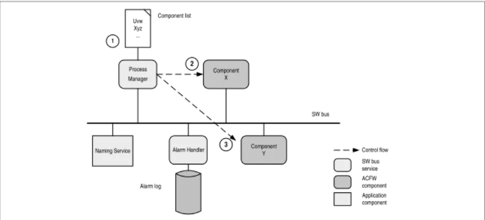
System architecture
Figure 3 displays the active components for a simple application. The arrows illustrate the control flow of the typical start-up sequence for the two application specific components (X and Y):1 The ProcessManager reads the component list, which contains the components to be activated and monitored during processing time of the application
2,3 Components X and Y are activated according to its position in the component list.
The message flow is not shown in the figure.
Conventions in the ACFW
Developers for the ACFW must follow specified conventions which in turn guarantee smooth implementation of independent modules:Figure 3: ACFW Overview Control flow SW bus service ACFW component Application component Process Manager Alarm Handler Component X Component Y Naming Service Alarm log SW bus 1 Component list 2 3 Uvw Xyz ...
18
Naming
Naming service, Alarm Handler and Process Manager are alwaysavaila-ble to the clients.
Availability
Process Manager and Alarm Handler are bound to naming service ofthe software bus
For the implementation of an application component a set of rules con-cerning robustness, component behaviour, naming, interfaces etc. is defined.