As
IP Serv
ssessm
vices In
ment of
ATIS-ntercon
Require
I-00000
nnect T
ements
045
Technic
s and S
cal Rep
pecific
Sepport:
cations
ptember 201141
1 Executive
Summary
1.1 Problem Statement
With the widespread deployment of high-speed wireless and wired broadband networks, operators are migrating their existing services such as voice and SMS into an all-IP implementation. In addition, new services, such as HD voice and video communications are being introduced into the all-IP networks. As a result, operators need to ensure interconnection and interoperability between service providers (e.g., Fixed, Wireless and Cable) for all IP-based services, both existing and forward-looking services. Standards have been defined by leading SDOs (e.g., IETF, ITU, 3GPP, PacketCable, GSMA, i3Forum, SIPForum, ATIS PTSC) to address interoperability. However, many options exist across these overlapping standards, and agreement as to which of the specifications to base the interconnect upon is often a key initial step.
1.2 Objective/Scope
The objective of the focus group is to define a strategy for developing an IP services interconnect specification suitable for all service provider types (wireless, wireline, and cable), encompassing basic, advanced, and future services.
The scope includes forward-looking services such as HD Voice, Video, Messaging, and Data. Requirements are identified for a set of interconnection profiles built on existing standards to enable these services and to deliver a consistent user experience across all types of networks (e.g., Wireless, Fixed, and Cable).
This analysis is complementary to a joint effort with the SIP Forum (the ATIS/SIP Forum IP-NNI Task Force) to develop a fully specified IP-NNI for voice services.
1.3 Analysis Model & Methodology
Representative use cases are identified for each IP service to assess the standards coverage across the key technical areas of services interconnect including session establishment and signaling, addressing and routing, and media handling.
1.4 SDO/Gap Analysis
Any areas where existing specifications for interconnection of advanced services are inconsistent or incomplete are identified.
2 Reference
Architecture
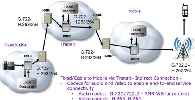
Figure 2.1 illustrates the interconnection reference model created by the ATIS Packet Technologies and System Committee (PTSC) for IP NNI supporting VoIP, video, and data. Illustrated are Border Elements (BEs) to enable IP interconnection between Service Providers. A BE includes an Interconnect Session Border Controller and Data Border Function.
IP interco Whicheve IP service
3 IP
S
3.1 HD
Wideband audio res extends t speech. T narrowba relaxes th3.1.1 R
Key stand Multi-rate 1 http://en.w F onnection ma er option is ch es may be depServices
D Voice
d audio, also sulting in high he frequency The range of nd telephone he bandwidthRelevant St
dardized wide Wideband), wikipedia.org/w Figure 2. 1 - A ay be accomp hosen is deter ployed on Sos
known as H h definition v y range of au f the human e calls limit au limitation andtandards
eband codec EVRC-NW wiki/HD-Voice ATIS IP-IP N plished via d rmined by mu ftswitch-base HD voice, refe voice quality dio signals a voice extend udio frequenc d transmits in s include: IT (Enhanced V 2 NI Interconn direct point-po utual agreeme ed architecture ers to the ne compared to and doubles t ds from 80 H cies to the rathe audio fre
U G.722, G.7 Variable Rate
nect Referenc
oint connectiv ent of the ope
es as well as ext generation o standard di the sampling Hz to 14 kHz ange of 300 H quency range 722.2 (also k e Narrowband ce Model vity or via IP erators. IMS. n of voice qu igital telepho rate, resultin z but traditio Hz to 3.4 kHz e of 50 Hz to known as AM d-Wideband) P eXchange
uality for telep ony "toll quali ng in higher q nal, voiceban z. Wideband 7 kHz or high MR-WB – Ada , and IETF O (IPX). phony ity". It quality nd, or audio her.1 aptive Opus.
3
With many additional wideband codecs in commercial use, industry convergence towards mandating a single codec is unlikely in the near term. It is hoped that a core subset of wideband codecs will achieve general market adoption and this will help facilitate interworking and reduce the need for transcoding. HD Voice for 3GPP terminals and networks uses the AMR-WB codec defined in ITU-T Recommendation G.722.2 and 3GPP TS 26.190. The HD voice service on LTE networks complies with 3GPP TS 26.114 and GSMA PRD IR.92 (VoLTE). 3GPP2 (CDMA) terminals that implement HD voice use the EVRC-NW (Enhanced Variable Rate Narrowband-Wideband) as specified in 3GPP2 C.S0014. Further technical details of AMR-WB are described in GSMA PRD IR.36.
ETSI TISPAN defines in TS 102 527 enhancements to the standards used by cordless phones, to enable wideband audio. The DECT Forum references this in their Cordless Advanced Technology – Internet and Quality (CAT-iq) initiative. CAT-iq addresses wireless broadband home connectivity in the protected frequencies used by Digital Enhanced Cordless Telecommunications (DECT) devices. In turn, there has been collaboration between CAT-iq and the Home Gateway Initiative (HGI), which is evolving the building blocks for Broadband Service Providers to deliver digital services to the home.
3.2 Video Call
See GSMA PRD IR.94 and GSMA PRD RCC.07 (RCS 5.1) ¶ 3.9. Point-to-point video communication between two parties.
IP-based Video Call between two devices with synchronization between the audio and video streams, thus providing lip synchronization. For voice the IP-based Voice Call service is used.
The continuity of an IP-based Video Call relies on the continuity of the IP connectivity. The establishment of the IP Video Call session can be achieved in three possible ways:
1. ‘Direct launch’, if no previous IP-based Voice Call was established between the contacts. 2. ‘Upgrade to IP-based Video Call’, if the users were already engaged with each other in an
IP-based Voice Call communication.
3. ‘Replace a CS voice with an IP-based Video Call’, if the users were already engaged with each other in a CS voice communication.
3.2.1 Relevant Standards
GSMA PRD IR.94 defines an IMS profile for a Conversational Video Service. GSMA PRD RCC.07 (RCS 5.1) defines a set of services known as the Rich Communications Suite. That set includes several video –based services, including Video Call as described above.
Internet browser-based video communication services are now emerging, and a framework of standards known as WebRTC is being jointly developed by the IETF and W3C (reference
http://www.w3.org/2011/04/webrtc/ and http://datatracker.ietf.org/wg/rtcweb/documents/).
3.3 Standalone Messaging
See GSMA PRD RCC.07 (RCS 5.1) ¶ 3.2.Integral part of the RCS framework that includes both text and multi-media messaging services based on OMA CPM as evolution from SMS and MMS. It includes the following main features:
Standalone messaging (text and multimedia);
Delivery and Display Notifications;
Support for multiple devices per user;
Deferred Messaging;
Central Message Storage; and
4
3.3.1 Relevant Standards
GSMA PRD RCC.07 specifies the standalone messaging capability for RCS based on OMA CPM’s SIP-based standalone messaging as described in GSMA PRD RCC.11 for the endorsement of OMA CPM 2.0 Conversation Functions.
3.4 One-to-One Chat
See GSMA PRD RCC.07 (RCS 5.1) ¶ 3.3.
The One-to-One Chat service enables the instantaneous exchange of messages in a session between two users.
The one-to-one Chat service enables two users, including two users across two different Service Provider networks, to exchange messages instantly. This section describes the guidelines for the one-to-one session setup and chat message exchange between OMA IM and OMA CPM.
3.4.1 Relevant Standards
GSMA PRD RCC.07 defines two different technical realizations of One-to-One chat; OMA SIMPLE IM or OMA CPM. GSMA PRD RCC.12 (RCS) endorses OMA SIMPLE IM 2.0 and GSMA PRD RCC.09, RCC.10 and RCC.11 endorse relevant aspects of OMA CPM 2.0.
3.5 Group Chat
See GSMA PRD RCC.07 (RCS 5.1) ¶ 3.4. The Group Chat service enables the instantaneous exchange of messages in a session between many users.
3.5.1 Relevant Standards
GSMA PRD RCC.07 defines two different technical realizations of chat; i.e., OMA SIMPLE IM or OMA CPM. Furthermore, GSMA PRD RCC.12 (RCS) endorses OMA SIMPLE IM 2.0 and GSMA PRD RCC.09, RCC.10 and RCC.11 endorse relevant aspects of OMA CPM 2.0.
3.6 File Transfer
See GSMA PRD RCC.07 (RCS 5.1) ¶ 3.5. The File Transfer service enables users to exchange different types of content (files) to another user, including to a user in a different Service Provider during an ongoing session or without having an ongoing session.
3.6.1 Relevant Standards
GSMA PRD RCC.12 endorses OMA SIMPLE IM 2.0, while GSMA PRD RCC.09, RCC.10, and RCC.11 endorse relevant aspects of OMA CPM 2.0. In addition, extensions described in A Session Description Protocol (SDP) Offer/Answer Mechanism to Enable File Transfer or IETF RFC 5547 are taken into account.
5
3.7 Content Sharing
See GSMA PRD RCC.07 (RCS 5.1) ¶ 3.6. Content sharing is the ability for users to exchange different types of content while in a session, such as a voice call, or as a standalone activity. There can be different sources for the shared content:
The front camera (“me”).
The rear camera (“what I see”).
A file (“video streaming” or “sending of a stored image”).
3.7.1 Relevant Standards
GSMA PRDs IR.74 defines video sharing within a call while GSMA PRD IR.84 defines standalone video sharing (i.e., outside of a call). GSMA PRD IR.79 specifies still image sharing during a call.
3.8 Geolocation Services
See GSMA PRD RCC.07 (RCS 5.1) ¶ 3.10. Geolocation services as part of GSMA RCS comprise the following 2 features:
1. The “Geolocation PUSH” service that allows an RCS user to push location information (that can be the user location or the location of a suggested meeting point) to another RCS user.
2. The “Geolocation PULL” service that allows an RCS user to retrieve the location information about another RCS user.
As it will describe in the next section, geolocation information may be provided as part of exchange of Social Presence information between RCS users. In addition, Geolocation Push is based on the RCS File Transfer service when used during a voice call and based on the RCS Chat service. The “show-us-on-map” feature makes use of Geolocation Push in the context of Group Chat. Geolocation Pull takes advantage of RCS File Transfer to fetch location information.
3.8.1 Relevant Standards
RCS Geolocation Services are described in GSMA PRD RCC.07.
3.9 Presence
Presence is a service that stores, accepts and distributes information on whether someone is available to communicate over a network. Presence can be implemented such that it is transparent to the end user (e.g., to indicate the advanced communication services supported by the device owned by someone in the user’s contact list). It can also be made accessible to the end user, e.g., by allowing the user to indicate his willingness to communicate, either directly or through integration with other applications. The latter is referred to in RCC.07 (RCS 5.1) ¶ 3.7 as Social Presence.
Rich presence is an enhanced form of presence awareness in which participants can determine if other users are online and if so, observe to a limited extent what they are doing and how they are doing it. Basic presence services divulge only the availability of another user. Rich presence goes further; subscribers can let others know for example:
their location;
whether their device is mobile;
its specifications;
operating system;
local time;
6
the level of privacy desired; and
whether the person is typing.
3GPP TR 23.841 (Technical Report) Presence service; Architecture and Functional Description:3GPP definition: The presence service provides the ability for the home network to manage presence information of a user's device, service or service media even whilst roaming. A user's presence information may be obtained through input from the user, information supplied by network entities or information supplied by elements external to the home network. Consumers of presence information, watchers, may be internal or external to the home network.
3.9.1 Relevant Standards
The lead industry standards in this space are based on IETF work and include Session Initiation Protocol for Instant Messaging and Presence Leveraging Extensions (SIMPLE) (RFC 3265, RFC 3856, RFC 3903) and Extensible Messaging and Presence Protocol (XMPP) (RFC 6120, RFC 6121, RFC 6122, RFC 3922, RFC 3923). These solutions have then been further advanced by organizations like OMA and XMPP Standards Foundation to facilitate greater interworking and the creation of modular network functions. There however remains significant technical variety between Presence solutions in deployment, with many solutions remaining closed implementations.
Operators have options to deploy Presence as a component capability for a range of multi-media services. This is the case, for example, for the GSMA Rich Communication Services as specified in GSMA PRD RCC.07, which builds on the Presence capabilities defined in OMA Presence SIMPLE. In GSMA RCS, Presence capabilities are applied not only for the exchange of Social Presence information described before in the section, but also used as mechanism for exchange of capability information and as alternative to the SIP OPTIONS capability discovery mechanism.
3.10 Video Conference/Collaboration
See GSMA PRD IR.39. The High Definition Video Conference (HDVC) service comprise point-to-point video calls and video conferences with one full duplex audio stream with tight synchronization to one main video stream and another video stream aimed for sharing of example presentation slides.
3.10.1 Relevant Standards
GSMA PRC IR.39 defines IMS-based High Definition Video Conference (HDVC) service.
3.11 Social Networking
A social networking service is an online service that focuses on facilitating the building of social networks or social relations among people who, for example, share interests, activities, backgrounds, or real-life connections. A social network service consists of a representation of each user (often a profile), his/her social links, and a variety of additional services. Most social network services are web-based and provide means for users to interact over the Internet, such as e-mail and instant messaging.
3.11.1 Relevant Standards
Social networking incorporates capabilities described in this document such as Presence, Location, Messaging, File Transfer, and Content Sharing. Some of the social networking services are proprietary and use proprietary protocols. Other social networking services are open and use standardized protocols. The set of standardized protocols utilized varies among the various social network services.
4 Us
4.1 HD
4.1.1 D
e Case A
D Voice
Direct Peer
1. VoIP d the AM indicat 2. Servic determ egress reach 3. When SBC-1 the int codecs the caAnalysis
ing, Trans
Figure device in Serv MR Wideband tion is referre ce Provider 1 mines that the s point from it a desired ing the call reque 1), that netwo erconnect ag s, if added, ar lling device.s
coder Free
e 4. 1 - Direc vice Provider d (AMR-WB) a d to as the “o network prov e call request ts own networ ress point to est reaches th rk element m reement betw re indicated to In this case, a 7e
t Peering, Tr 1 network ori and AMR nar offer”. ides originatin should be rou rk (I-SBC-1) t Service Prov he egress poi ay augment t ween Service o be less pref assume that i ranscoder Fr iginates a cal rrowband (AM ng services fo uted to Servic through which ider 2’s netwo int from Servi the “offer” wit Provider 1 an ferable than t it added G.71 ree l request, ind MR) codecs, in or the calling ce Provider 2 h to forward th ork (I-SBC-2) ice Provider 1 h additional c nd Service Pr the ones origi 11. It also allo icating suppo n that order. party, then . It determine he call reques ). 1’s network (I codecs, based rovider 2. Su inally offered ocates whate ort for This es an st, to -d on uch by ever8
resources are required to perform transcoding, should transcoding prove to be necessary.
4. When the call request reaches the ingress point to Service Provider 2’s network (I-SBC-2), that network element may augment the “offer” with additional codecs, based on the policies of Service Provider 2. As above, if codecs are added, they are indicated to be less preferable than the ones already in the offer. In this case, assume that it added nothing.
5. Service Provider 2 network provides terminating services for the called party, then forwards the call request to the device(s) with which the called number is registered. In this case, assume there is one such device (this is usually the case).
6. The terminating device selects the first codec in the offer that it is able to
support. Assume that to be AMR-WB. It generates an “answer” which indicates that it wants to use this codec.
7. The answer is propagated back toward the calling device. (Includes Step 8)
9. When the answer reaches I-SBC-1, that network element realizes that transcoding is not required and therefore releases the transcoding resources it allocated in step 3.
10. When the answer reaches the calling device, an end-to-end RTP path is established over which the audio media is exchanged in the AMR-WB format.
4.1.2 D
1. V A 2. S th its po 3. W ne ag inDirect Peer
Figur VoIP device in AMR and AMRervice Provid hat the call req
s own networ oint to Servic When the call etwork eleme greement bet ndicated to be
ing Requir
re 4. 2 - Direc Service Prov R-WB codecs der 1 network quest should rk (I-SBC-1) th e Provider 2’s request reach ent may augmtween Service e less preferab
ring Transc
ct Peering – vider 1 netwo . This indicat provides orig be routed to hrough which s network (I-S hes the egres ment the “offer e Provider 1 a ble than the o9
coding
Transcode A rk originates tion is referre ginating servic Service Prov h to forward th SBC-2). ss point from S r” with additio and Service P ones originally AMR or AMR a call request d to as the “o ces for the ca vider 2. It dete he call reques Service Provi onal codecs, b Provider 2. S y offered by t R-WB to G.71 t, indicating s offer”. alling party, th ermines an eg st, to reach a ider 1’s netwo based on the uch codecs, i he calling dev 1support for the en determine gress point fr desired ingre ork (I-SBC-1) interconnect if added, are vice. In this c e es rom ess , that case,
10
assume that it added G.711. It also allocates whatever resources are required to perform transcoding, should transcoding prove to be necessary.
4. When the call request reaches the ingress point to Service Provider 2’s network (I-SBC-2), that network element may augment the “offer” with additional codecs, based on the policies of Service Provider 2. As above, if codecs are added, they are indicated to be less preferable than the ones already in the offer. In this case, assume that it added nothing.
5. Service Provider 2 network provides terminating services for the called party, then forwards the call request to the device(s) with which the called number is registered. In this case, assume there is one such device (this is usually the case).m
6. The terminating device selects the last codec (G.711) since it is unable to support either AMR or AMR-WB. It generates an “answer” which indicates that it wants to use this codec.
7. The answer is propagated back toward the calling device. (Includes Step 8)
9. When the answer reaches I-SBC-1, that network element realizes that the codec indicated in the answer is one that it added to the offer. It therefore realizes that it needs to transcode the media between the codec selected by the called device (G.711) and one of the codecs offered by the calling device. Depending on the policy of SP 1, it may select either AMR or AMR-WB.
10. When the answer reaches the calling device, an end-to-end RTP path is established over which the audio media is exchanged. Between the calling device and I-SBC-1 the media is exchanged in AMR or AMR-WB format. Between I-SBC-1 and the called device the media is exchanged in G.711 format.
4.1.3 In
nDirect Pee
Figureering, Tran
e 4. 3 - InDirenscoding i
ct Peering, T 11n the Origi
Transcodinginating Ne
in the Origintwork
12
1. VoIP device in Service Provider 1 network originates a call request, indicating support for the G.722 and G.711 codecs. This indication is referred to as the “offer”.
2. Service Provider 1 network provides originating services for the calling party, then determines that the call request should be routed to Service Provider 2 via a transit network. (This use case assumes there to be an interconnect agreement between SP1 and SP2.) It determines an egress point from its own network (I-SBC-1) through which to forward the call request, to reach a desired ingress point to the transit network (I-SBC-2).
3. When the call request reaches the egress point from Service Provider 1’s network (I-SBC-1), that network element may augment the “offer” with additional codecs, based on the interconnect
agreement between Service Provider 1 and Service Provider 2. Such codecs, if added, are indicated to be less preferable than the ones originally offered by the calling device. In this case, assume that it added AMR-WB and AMR. It also allocates whatever resources are required to perform transcoding, should transcoding prove to be necessary.
4. When the call request reaches the ingress point to the transit network, no SDP manipulation is required since the transit network does not terminate the media.
5. When the call request reaches the egress point from the transit network facing Service Provider 2 (I-SBC-2), that network element may augment the “offer” with additional codecs, based on the
interconnect agreement between the transit provider and Service Provider 2. As above, if codecs are added, they are indicated to be less preferable than the ones already in the offer. In this case assume that it added nothing.
6. When the call request reaches the ingress point to Service Provider 2’s network (I-SBC-3), that network element may augment the “offer” with additional codecs, based on the policies of Service Provider 2. As above, if codecs are added, they are indicated to be less preferable than the ones already in the offer. In this case, assume that it added nothing.
7. Service Provider 2 network provides terminating services for the called party, then forwards the call request to the device(s) with which the called number is registered. In this case, assume there is one such device (this is usually the case).
8. The terminating device selects the AMR-WB codec since that is the first codec in the offer that it supports. It generates an “answer” which indicates that it wants to use this codec.
9. The answer is propagated back toward the calling device. (Includes Steps 10-12)
13. When the answer reaches I-SBC-1, that network element realizes that the codec indicated in the answer is one that it added to the offer. It therefore realizes that it needs to transcode the media between the codec selected by the called device (G.711) and one of the codecs offered by the calling device. By selecting a wideband codec (G.722), I-SBC-1 can ensure an end-to-end wideband media path. As before, the codec it selects is determined by the policies of SP 1. In this case, assume it selected G.722.
14. When the answer reaches the calling device, an end-to-end RTP path is established over which the audio media is exchanged. Between the calling device and I-SBC-1 the media is exchanged in G.722 format. Between I-SBC-1 and the called device the media is exchanged in AMR-WB format.
4.1.4 In
FignDirect Pee
gure 4. 4 - Inering, Tran
Direct Peerinnscoding i
ng – Transco 13n both Orig
oding in bothginating a
h Originatingnd Transit
g and Transitt Networks
t Networkss
14
1. VoIP device in Service Provider 1 network originates a call request, indicating support for the AMR-WB and AMR codecs. This indication is referred to as the “offer”.
2. Service Provider 1 network provides originating services for the calling party, then determines that the call request should be routed to a transit network. (This use case assumes that the originating network does not know or has no interconnect agreement with, the terminating network) It determines an egress point from its own network (I-SBC-1) through which to forward the call request, to reach a desired ingress point to the transit network (I-SBC-2).
3. When the call request reaches the egress point from Service Provider 1’s network (I-SBC-1), that network element may augment the “offer” with additional codecs, based on the interconnect agreement between Service Provider 1 and the transit network. Such codecs, if added, are indicated to be less preferable than the ones originally offered by the calling device. In this case, assume that it added G.722 and G.711. It also allocates whatever resources are required to perform transcoding, should transcoding prove to be necessary.
4. When the call request reaches the ingress point to the transit network, no SDP manipulation is required since the transit network does not terminate the media. The transit network determines that the call request is destined for Service Provider 2, and identifies an egress point from its own network (I-SBC-3) through which to forward the request, to reach a desired ingress point to the terminating network (I-SBC-4).
5. When the call request reaches the egress point from the transit network facing Service Provider 2 (I-SBC-3), that network element may augment the “offer” with additional codecs, based on the interconnect agreement between the transit provider and Service Provider 2. As above, if codecs are added, they are indicated to be less preferable than the ones already in the offer. In this case assume that it added G.729A.
6. When the call request reaches the ingress point to Service Provider 2’s network (I-SBC-4), that network element may augment the “offer” with additional codecs, based on the policies of Service Provider 2. As above, if codecs are added, they are indicated to be less preferable than the ones already in the offer. In this case, assume that it added nothing.
7. Service Provider 2 network provides terminating services for the called party, then forwards the call request to the device(s) with which the called number is registered. In this case, assume there is one such device (this is usually the case).
8. The terminating device selects the G.729A codec since that is the first codec in the offer that it supports. It generates an “answer” which indicates that it wants to use this codec.
9. The answer is propagated back toward the calling device.
10. When the answer reaches I-SBC-3, that network element realizes that the codec indicated in the answer is one that it added to the offer. It therefore realizes that it needs to transcode the media between the codec selected by the called device (G.711) and one of the codecs that was in the offer it received in step 4. The codec it selects is determined by the policies of the transit network provider. In this case, assume it selected G.711. It is possible, but not mandatory, for SBC3 to accept the first codec offered in order to avoid additional transcoding (this includes Step 11). 12. When the answer reaches I-SBC-1, that network element realizes that the codec indicated in the
answer is one that it added to the offer. It therefore realizes that it needs to transcode the media between the codec it sees in the answer (G.711) and one of the codecs that was in the offer it received in step 2. The codec it selects is determined by the policies of SP 1. In this case, assume it selected AMR.
13. When the answer reaches the calling device, an end-to-end RTP path is established over which the audio media is exchanged. Between the calling device and I-SBC-1 the media is exchanged in AMR format. Between I-SBC-1 and I-SBC-3 the media is exchanged in G.711 format. Between I-SBC-3 and the called device the media is exchanged in G.729A format. (this includes Step 14).
4.1.5 D
1. VoIP indica 2. Servic call re netwo Servic 3. When netwo agree to be added shoulDirect Peer
Fi device (e.g., ating support f ce Provider 1 equest should ork (I-SBC-1) ce Provider 2 n the call requ ork element m ement betwee less preferab d AMR-WB an d transcodinging – Tran
igure 4. 5 - D Tablet suppo for the Opus network prov d be routed to through whic ’s network (I-uest reaches t may augment en Service Pro ble than the on nd AMR. It a g prove to bescoding O
Direct Peering
orting webRTC and iLBC cod vides originat o Service Prov ch to forward t
SBC-2). the egress po
the “offer” wit ovider 1 and S nes originally lso allocates necessary. 15
OPUS to AM
g – Transcod C) in Service decs. This inding services f vider 2. It det the call reque oint from Serv th additional c Service Provi y offered by th whatever res
MR-WB
ding Opus to Provider 1 ne dication is ref for the calling termines an e est, to reach a vice Provider codecs, base ider 2. Such he calling dev sources are re o AMR-WB etwork origina ferred to as th g party, then d egress point f a desired ingr 1’s network ( ed on the inter codecs, if ad vice. In this ca equired to perates a call req he “offer”. determines th from its own ress point to (I-SBC-1), tha
rconnect ded, are indic ase, assume rform transco quest, at the at cated that it oding,
16
4. When the call request reaches the ingress point to Service Provider 2’s network (I-SBC-2), that network element may augment the “offer” with additional codecs, based on the policies of Service Provider 2. As above, if codecs are added, they are indicated to be less preferable than the ones already in the offer. In this case, assume that it added nothing.
5. Service Provider 2 network provides terminating services for the called party, then forwards the call request to the device(s) with which the called number is registered. In this case, assume there is one such device (this is usually the case).
6. The terminating device selects the AMR-WB codec since that is the first codec in the offer that it supports. It generates an “answer” which indicates that it wants to use this codec.
7. The answer is propagated back toward the calling device.
8. When the answer reaches I-SBC-1, that network element realizes that the codec indicated in the answer is one that it added to the offer. It therefore realizes that it needs to transcode the media between the codec selected by the called device (AMR-WB) and one of the codecs offered by the calling device. Depending on the policy of SP 1, it may select either Opus or iLBC. In this case assume it selected Opus (since doing so yields an end-to-end wideband audio stream). (Includes Step 9.)
10. When the answer reaches the calling device, an end-to-end RTP path is established over which the audio media is exchanged. Between the calling device and I-SBC-1 the media is exchanged in Opus format. Between I-SBC-1 and the called device the media is exchanged in AMR-WB format.
4.1.6 SDO Assessment/Gap Analysis
4.1.6.1 3GPP
4.1.6.1.1 Session Establishment & Signaling
3GPP TS 24.229 defines the functions at the SIP protocol layer for an Interconnection Border Control Function (IBCF). IBCFs communicate with each other to perform interconnection between IP Multimedia networks. Trust relationships and trust domains may be defined by inter-operator agreements for individual services and/or individual SIP header fields. The offer/answer model with the SDP as defined in IETF RFC 3264 is used for codec negotiation and selection.
4.1.6.1.2 Addressing & Routing
3GPP TS 24.229 defines URI formats that must be supported on the IP-NNI. Additional routing capabilities are necessary for support of transit, roaming, and interconnection traffic. Routing procedures should analyze the destination address and determine whether to route to another network, directly, or via the IBCF, or to the BGCF, or the I-CSCF in its own network. This analysis may use public (e.g., DNS, ENUM) and/or private database lookups, and/or locally configured data and may, based on operator policy, modify the Request-URI (e.g., to remove number prefixes, to translate local numbers to global numbers, etc).
4.1.6.1.3 Media Handling
Codecs applicable at the IP-NNI may be a subject of interworking agreements. To avoid the scenario where transcoding is performed several times, applicable codecs at the NNI should be restricted as little as possible in the inter-operator agreements. Transcoding can be performed in an IMS network serving an SDP offerer or in an IMS network serving an SDP answerer. Inter-operator agreements can clarify if it is preferred that the IMS network serving an SDP offerer or IMS network serving an SDP answerer modify an SDP offer to offer media transcoding. Optimal Media Routing (OMR) may be used to identify and remove unnecessary media functions from the media path for each media stream associated with a session, to minimize end-to-end delay and to minimize the use of transport network resources. OMR procedures should be agreed between operators.
17
4.1.6.2 GSMA
4.1.6.2.1 Session Establishment & Signaling
GSMA PRD IR.92 as IMS profile for Voice of LTE defines that the “IMS well-known APN” is required for the establishment of the PDN connection needed to set up a VoLTE session. The IMS well-known APN is defined in GSMA PRD IR.88.
Within the SP network, if the PDN connection established during the initial attach is to an APN other than the IMS well-known APN, then prior to registering with IMS the UE must establish another PDN connection to the IMS well-known APN.
A default bearer must be created when the UE creates the PDN connection to the IMS well known APN, as defined in 3GPP TS 23.003. A standardized QCI value of five (5) must be used for the default bearer. It is used for IMS SIP signaling.
UE and IMS core network follow 3GPP TS 24.229 for establishment and termination of a VoLTE call. For the purpose of indicating an IMS communication service to the network, the UE must use an ICSI value in accordance with 3GPP TS 24.229. The ICSI value used must indicate the IMS Multimedia Telephony (MMTel) service, which is urn:urn-7:3gpp-service.ims.icsi.mmtel, as specified in 3GPP TS 24.173.
A VoLTE UE must be ready to receive responses generated due to a forked request and behave according to the procedures specified in IETF RFC 3261, 3GPP TS 23.228, and 3GPP TS 24.229.
In addition, if a VoLTE UE detects that in-band information is received from the network as early media, the in-band information received from the network shall override locally generated communication progress information as described in 3GPP TS 24.628.
Similar functionality is endorsed in GSMA PRD IR.58, the IMS profile for Voice over HSPA.
4.1.6.2.2 Addressing & Routing
GSMA PRD IR.65 defines network-level roaming and interworking guidelines for IMS services such as for Voice over IMS (i.e., GSMA PRDs IR.92 and IR.58). In addition, GSMA PRD IR.67 provides recommendations on DNS (including ENUM) to facilitate successful interworking of inter-Service Provider services.
GSMA PRD IR.65 endorses interworking by means of the IMS NNI as documented in 3GPP TS 29.165, and the support of IPv4 only, IPv6 only or both. Support of the different IP versions on the Inter-Service Provider IP Backbone network (e.g., IPX) is specified in GSMA PRD IR.34 and GSMA PRD IR.40.
IMS user addressing is defined in 3GPP TS 23.228 and its format is defined in 3GPP TS 23.003. GSMA PRD IR.92 further clarifies that UEs and IMS core network must support Public User Identities in the form of SIP URIs (both alphanumeric and those representing Mobile Subscriber ISDN Numbers (MSISDNs)) and Tel URIs. Support of MSISDN as a Public User Identity, the network must associate a Tel URI with an alphanumeric SIP URI using the mechanisms specified in TS 23.228 and TS 24.229.
Support of IP addressing used by the user is subject to the requirements for the underlying IP network, e.g., for LTE, see GSMA PRD IR.88, respectively.
As such, GSMA PRD IR.65 specifies that Roaming should be at least as optimal as that of the Circuit Switched domain.
The Inter-Service Provider IP Backbone should support OMR functionality as specified in 3GPP TS 29.079, if it is allowed between two operators to prevent the user plane to be routed back to HPLMN of roaming users.
18
4.1.6.2.3 Media Handling
GSMA PRD IR.92 specifies that the UE must support the Adaptive Multi-Rate (AMR) speech codec, as described in 3GPP TS 26.071, TS 26.090, TS 26.073, and TS 26.104, including all eight modes and source rate controlled operations, as described in 3GPP TS 26.093. The UE must be capable of operating with any subset of these eight codec modes.
If wideband speech communication is offered, the UE must support AMR wideband codec as described in 3GPP TS 26.114, TS 26.171, TS 26.190, TS 26.173, and TS 26.204, including all nine modes and source controlled rate operation 3GPP TS 26.193. The UE shall be capable of operating with any subset of these nine codec modes.
Entities in the IMS core network that terminate the user plane in support of Circuit Switched interworking and apply TFO and/or TrFO shall support:
AMR speech codec modes described in 3GPP TS 26.071, TS 26.090, TS 26.073, and TS 26.104. Entities in the IMS core network that terminate the user plane supporting wideband speech
communication and supporting TFO and/or TrFO shall support:
AMR-WB speech codec modes described in 3GPP TS 26.171, TS 26.190, TS 26.173, and TS 26.204.
IR.92 endorses media capabilities specified in 3GPP TS 26.114. GSMA PRD IR.92 also describes the needed SDP support in UEs and in the IMS core network and it describes the necessary media capabilities both for UEs and for entities in the IMS core network that terminate the user plane.
4.1.6.3 PacketCable
4.1.6.3.1 Session Establishment & Signaling
There are two versions of PacketCableTM: PacketCable 1.5 and PacketCable 2.0. PacketCable 1.5 is a Softswitch-based architecture. SIP session establishment signaling is defined in PKT-SP-CMSS1.5-I07-120412, which in turn follows the IETF SDP offer/answer procedures defined in RFC 3264. PacketCable 1.5 supports G.722 as defined in PKT-SP-CODEC1.5-I04-120412.
PacketCable 2.0 is an IMS-based architecture that supports the session signaling procedures defined in 24.229 (that ultimately support the IETF SDP offer/answer procedures in RFC 3264). PacketCable 2.0 HD-voice extensions are defined in PKT-SP-HDV-SIP-I03-120823 and PKT-SP-CODEC-MEDIA-C01-140314.
PacketCable NNI SIP signaling procedures are defined in PKT-SP-IGS-C01-130930. It assumes a direct-IP-peering architecture (no transit network). Scope is limited to basic narrow-band voice calling, plus common voice features. Use of PRACK is avoided, to minimize signaling traffic, and since the frequency of lost messages in today’s networks is very low. QoS preconditions are not used, to minimize post-dial ringing delay, and since local policy normally dictates that media session is established via best-effort when QoS allocation fails.
Summary: PacketCable is similar to 3GPP in that it supports the session establishment procedures described in 24.229, and ultimately RFC 3264. In general, PacketCable does not adopt many of the private P_ headers defined for IMS (e.g., does not support P-Early-Media, P-Asserted-Service-ID, etc).
4.1.6.3.2 Addressing & Routing
Similar to 3GPP at the session-signaling level.
PKT-SP-ENUM-PROV defines the architecture and procedures for sharing routing information between peering partners (i.e., how a service provider pushes its ingress routing information to a peer, the data
19
models for the peer routing registry, and how a provider can add their egress routing information to the ingress routing info received from a peer).
PKT-SP-ENUM-SRV defines the procedures used in the originating network for obtaining peer routing information at call setup time (i.e., procedures for querying the registry routing database. It defines two options; one based on ENUM, and one based on SIP (i.e., using SIP redirect). The ENUM procedures are similar to what is defined in 24.229, but with more detail.
NOTE: The above specifications are not currently supported in deployed cable networks. In the context of this document, these specifications should be viewed simply as informative resources describing one of many possible NNI routing solutions.
4.1.6.3.3 Media Handling
PKT-SP-IGS-C01-130930 defines procedures for early media, including the case of sequential forking in terminating network; say where, before 200OK-answer, call is routed to media server to collect PIN, then routed to called user to receive custom ringback tone, etc).
Currently only wideband codec mandated is G.722. The expectation is that additional wideband codecs will be added to the list in the future (e.g., OPUS).
4.1.6.4 I3forum
The i3forum document “Enabling HD voice continuity in international calls” Release 1.0 addresses a broad set of high definition voice codecs including but not limited to the codecs dealt with by GSMA with its HD Voice specification: i.e., G.722 for fixed communication and G.722.2 (WB-AMR) for mobile communication.
NOTE: i3forum only addresses indirect interconnection for international voice.
4.1.6.4.1 Session Establishment & Signaling
Ordinarily Media negotiation use the offer-answer model (RFC 3264): the offer is contained in the SDP body of the initial INVITE, and, given that the call is successfully established, the answer is in the body of the 200 OK message.
For TrFO, follows TS 23.153 where wideband codecs, if available, should be given preference in the codec negotiation.
For AMR-WB signaling, all of the control parameters are mapped in the SDP body of the SIP messages. They are included in the a=fmtp attribute of the AMR-WB codec.
Transit carrier could be “Proactive” (involved in the Codec negotiation) or “Passive” (not involved) but in Proactive Mode the Carrier should not intervene if:
SDP body with a distinctive attribute a=3gOoBTC, which conveys a SIP session establishment using the TrFO procedure is being negotiated by the SPs.
There are cconnectivity preconditions (IETF RFC 5898). The terminating user will not be alerted unless end-to-end connectivity has been previously ensured.
There are QoS preconditions (IETF RFC 3312). The terminating user will not be alerted unless QoS parameters can be guaranteed.
There are Security preconditions (IETF RFC 5027). The terminating user will not be alerted unless a secure communication between endpoints can be guaranteed.
20
4.1.6.4.2 Addressing & Routing
I3 Forum White Paper Techniques for Carrier’s Advanced Routing and Addressing Schemes (Release 1.0 May 2010 and Release 2.0 May 2011) offers a strategy for the evolution of routing and addressing taking into account the realities of the current environment. This strategy focuses on leveraging existing and planned service provider efforts to create registries for number portability corrected data and supplementing these to meet the particular needs of international carriers.
Routing: Rarely takes into account the media capabilities of the Service Providers for the configuration of its routing policy.
4.1.6.4.3 Media Handling
Non TrFO Indirect scenarios analyzed by the i3F include:
Preconditions.
The offer/answer are transported in the SIP INVITE/OK messages respectively. There is only “audio” as media type in the m= line(s).
No ReINVITEs that modify the media session are sent in the middle of the call. No SIP Preconditions are used, or they have already been met.
The IPX Provider has transcoding capabilities. Scenarios:
o Session initiated by a SP offering only mandatory wideband codecs (G.722/AMR-WB).
o The terminating SP accepts one or both the wideband codecs present in the offer.
o The terminating SP only accepts narrowband codecs.
o The terminating SP supports one or more wideband codecs, but different from the ones contained in the offer.
Session initiated by a SP offering mandatory wideband codecs.
Session initiated by a SP offering only Opus.
o The terminating SP accepts Opus.
o The terminating SP accepts only AMR-WB or G.722, not Opus.
o The terminating SP accepts other codecs.
Other scenarios.
o The initiating SP only offers non-mandatory high quality codecs.
4.1.6.5 ATIS
4.1.6.5.1 Session Establishment & Signaling
Currently under discussion in PTSC in their Issue S0040, IP Network-to-Network Interface, Phase 2), Interconnection parameters are based on 3GPP TS 24.229. It describes the procedures the BCSF shall use for both the trusted and non-trusted case. Support for SCTP is optional.
4.1.6.5.2 Addressing & Routing
The following URI formats are supported:
SIP URI defined in IETF RFC 3261 [13];
tel URI, or SIP URI with tel URI parameters, as defined in IETF RFC 3966 [14];
IM URI defined in IETF RFC 3860 [15]; and
PRES URI defined in IETF RFC 3859 [16]. Interworking may be IPv4, IPv6, or both.
21
Currently under discussion in PTSC in their Issue S0040, IP Network-to-Network Interface, Phase 2 (Interconnection Models) does not indicate a preference for a particular interconnection model, but warns of the dangers of routing the signaling and media separately. RAVEL and OMR are identified as possible alternative routing strategies when roaming.
ATIS-0416001-00012 (Next Generation Networks Carrier Interconnection Use Cases for Ordering) supports both direct and indirect interconnect use cases.
A joint ATIS SIP Forum task force is developing the IP Interconnection Routing Document. The document discusses the existing in-use and proposed routing solutions to facilitate the exchange of traffic associated with IP-based services between North American service providers.
4.1.6.5.3 Media Handling
Codecs applicable at the II-NNI may be a subject of interworking agreements, but the list of possible codecs are found in 3GPP TS 26.114 and ETSI TS 181 005. AMR-WB (G.722.2), G.722, EVRC-WB are supported wideband codecs.
The IBCF, the MRFC, or other IMS network entities may do transcoding. Media security may be none (physical security), IPsec, or SRTP.
4.1.6.6 ITU
4.1.6.6.1 Session Establishment & Signaling
ITU-T Recommendation Q.3401 NGN NNI signalling profile (protocol set 1) defines a SIP profile for the service control function at the NNI interface based on IETF RFC 3261.
4.1.6.6.2 Addressing & Routing
There can be several ways for determining the destination of the SIP message based on the tel URI; ENUM-based routing, number-based routing. In the ITU Recommendation, it is assumed that each network knows the address information of the peer network based on the number.
4.1.6.6.3 Media Handling
Media availability in a SIP session: The terminating-side network of the NNI shall pass any media packets in the direction toward the originating party as soon as they are available.
The originating-side network of the NNI:
o shall pass media packets from the originating party in the direction toward the terminating party upon and after receiving a final SDP answer within a SIP 2xx response to the INVITE for normal dialog; may pass media packets from the originating party in the direction toward the terminating party as early as the first SDP answer has occurred. A network, as a policy, may choose not to send media packets from the originating party until the final SDP offer/answer has been made in order to avoid theft-of-service in cases where usage-sensitive billing is employed.
2
This document is available from the Alliance for Telecommunications Industry Solutions (ATIS) at <https://www.atis.org/docstore/product.aspx?id=28154>.
22
Codec support:
To enable the provision of voice service with a superior quality, it is highly recommended that the list contain a wideband codec such as AMR-WB [ITU-T G.722.2], VMR-WB [TIA-1016], G.722 [ITU-T G.722], G.729.1 [ITU-T G.729.1].
4.1.6.7 W3C WebRTC & IETF RTCWeb
4.1.6.7.1 Session Establishment & SignalingSession establishment signaling is not specified although the WebRTC API creates and consumes SDP offers and answers to negotiate media capabilities for establishing sessions between browsers.
IETF Internet-Draft draft-ietf-rtcweb-jsep-06, defines extensions to SDP offer/answer to:
a) multiplex multiple media streams on same 5-tuple; i.e., transport (UDP/TCP), plus source/destination IP:port,
b) secure streams with DTLS/SRTP, c) establish data channel, and
d) other miscellaneous enhancements.
Draft-ietf-rtcweb-jsep normatively references additional IETF draft documents, such as draft-ietf-mmusic-sdp-bundle-negotiation, that must be supported to enable the above extensions.
4.1.6.7.2 Addressing & Routing
Not Specified.
4.1.6.7.3 Media Handling
WebRTC proposes that all implementations must support OPUS for wideband voice, but still allows other codecs to be used if both sides support them, and if they are negotiated.
4.1.7 Key Issues to be Addressed by IP Services NNI
4.1.7.1 Wideband Codec Support
The more broadly supported HD codecs currently specified in standards include:
G.722.
G.722.2 (Adaptive Multi-rate - Wideband).
OPUS.
As a general guideline, transcoding is to be avoided at the NNI where possible. The joint ATIS SIP Forum IP-NNI Task force has as a key objective to specify an audio codec selection strategy that minimizes the need for transcoding and a transcoding strategy that balances the workload between
originating and terminating carrier. In order to provide a more seamless solution for HD voice end-to-end
it is recommended that the ATIS/SIP Forum NNI Task Force address mandatory HD codecs as part of the definition of the NNI IP profile.
23
4.1.7.2 Support of QoS Preconditions
Preconditions are a set of constraints about a session that are introduced in the offer. The recipient of the offer generates an answer but does not alert the user or proceed with the session establishment until after the preconditions are met. Quality of Service preconditions are included in the SDP description. PacketCable and some other industry segments do not currently support the use of preconditions. It is recommended that the ATIS/SIP Forum NNI Task Force evaluate the need to address preconditions as part of the definition of the NNI IP profile, and that the same procedures be used for the other services considered in this document.
4.1.7.3 Early Media Support
Early media is the concept of delivering a media stream (e.g., audio and video) prior to call answer or session establishment. Support for early media is important both for interoperability with the Public Switched Telephone Network (PSTN) and for billing purposes. Varying implementations exist for the support of early media. In some cases early media is indicated by the presence of a P-Early-Media header in a 18X response. It is recommended that the ATIS/SIP Forum NNI Task Force define the procedures for early media across the NNI as part of the IP Interconnect profile, and that the same procedures be used for other services.
4.1.7.4 IP Interconnection Addressing Data
GSMA is exploring the concept of service identification at the NNI. The requested service needs to be clearly identified at the NNI in a fashion that allows each network to understand what it needs to provide and to determine the applicable charging, if any. It is noted that some service providers consider exposing their subscriber service adoption to be undesirable from a competitive standpoint.
In principle this can all be derived from the various headers in the SIP session request (see RFC-5897). However that derivation can be computationally complex. IETF has specified in RFC-6050 a pair of SIP headers (P-Preferred-Service and P-Asserted-Service) that may be used to encode in the SIP message the result of this derivation, so that downstream network elements need not repeat the process of “figuring out” what service is being requested. Use of these headers should be considered in future NNI work.
4.2 Video Call
4.2.1 Capability
Discovery
It’s sometimes desirable to be able to discover the enhanced services supported by the device at the far end of an existing communications session; including a session that spans an NNI. Similarly, it can be useful to know prior to requesting a communications session what the remote device(s) support. For example, the following are sample applications of such mechanisms:
Originating network can screen/update the SDP to exclude video attributes to minimize the chances of audio call failure due to far end device’s inability to handle SDP with video and audio. For example, some devices cannot handle large SDP message bodies, nor SDP message bodies containing multiple media (m=) lines.
The UI display can be updated to reflect far end capability. For example, the contact list entry on a mobile device corresponding to a number assigned to a friend’s PC Client, can have a “video call” icon activated that in other cases (where the remote device is not known to be video capable) is greyed out.
24
Static Device Configuration (if allowed).
NNI configuration (e.g., one network might be configured with the knowledge that the peer network does not support certain services).
An industry database could be configured with the supported services of the far end party.
Dynamic discovery.
o Prior to initiation of a session request
o After a session has been established
Standard codec negotiation (video attributes in SDP) during session establishment.
During the IP Transition period, there may be a high proportion of advanced services that are not possible end-to-end until service adoption is more ubiquitous. It may be highly desirable to optimize the efficiency of the network with a database lookup rather than incur the extra call setup signaling if the majority of these sessions will be rejected or downgraded to basic voice. This database concept has been raised under the “Addressing and Routing” sections amongst the various use cases throughout this document. This need is not limited to video sessions.
How such an industry database is provisioned and by whom, the protocols (e.g., ENUM) used to access it, and whether this database stores the far end data or is a pointer to such data or a hybrid of these models is beyond the scope of this Focus Group. Refer to the SIP NNI joint ATIS/SIP Forum taskforce for more information on industry databases to support efficient call setup and routing.
The first two options are network-specific and not subject to standardization.
GSMA PRD RCC.07 (RCS 5.1) specifies two mechanisms to achieve dynamic service discovery; one based on SIP Options (¶ 2.6.1.1) and one based on use of Presence (¶ 2.6.1.2). Either approach can be used either prior to initiation of a session request or after a session has been established.
Dynamic service discovery during the process of session establishment could be “just SIP”; with the caveat that only “positive inferences” can be drawn. For example one user might attempt to discover another user’s ability to support video, by sending a request for a video session. If that request is accepted, the first user can infer that the second user supports video. But if that request is rejected, the second user cannot know why.
The following diagram shows an example where capability discovery occur independent of session establishment.
NOTE 3840. video approp Althou the far end ca may n
4.2.2 V
The follow illustrate t required t Figu E: Support of u OPTIONS me session. Tryin priate for capab ugh, permitted r-end is consid apability and th ot be set up.Video Call
wing diagram the basic sce o ensure syn ure 4. 6 - Cap using OPTION essaging can b ng to establish bility discovery in a SIP dialog ered optional a he UE at far-en shows an ex enarios altho chronization o pability Disco S for capabilit be used to disc h a video sessi y. g, the use of t and based on b nd doesn’t imp xample video ugh it is reco of audio and 25 overy before ty discovery ac cover far end v ion implies thehe SIP OPTIO bilateral agreem
lement this cap
call in an IM ognized that video. e Establishin cross NNI is o video support e far end user
ONS method to ment. If a UE u pability discove S environme in practice a ng Video Call optional as ind status without may be alerte o obtain capab uses SIP OPTIO
ery mechanism nt. This diag additional me l dicated in IETF trying to estab ed which may bility information ONS to learn t m, then the vide
gram is provid echanisms ma F RFC blish a not be n from he far-eo call ded to ay be
Figuree 4. 7 - Video
26
4.2.3 U
The follow The followUse Case -
wing diagram wing diagramUpgrading
illustrates a s Figur shows how ag Audio Ca
successful up re 4. 8 - Upgr a rejection of v 27all to Video
pgrade from a rading Audio video upgradeo
udio to video o Call to Vide e should work call. eo k.The followwing diagram
Figure 4
shows a varia
. 9 - Rejected
ant of how rej
28
d request to
ject can happ
upgrade to v
pen.
NOTE: The SDP. The may be sim
4.2.4
U
The intent a) Tw ov se b) or ov The recei removed descriptor request w conferenc removed or if the vi If the rec communic ongoing v e B Party shou originating net mplified where tUse Case –
t is to describ wo users sta ver IP call (i. ession; r engaging in ver IP call) an iving user’s d by sending a r is set to ze with an SDP o ce participant it is up to net ideo conferen ceiving user cation, only a voice over IP c Fig ld accept what twork is not ob the equipment– Video the
be a possible rting a voice e., upgrade v n a "direct vid nd do not nee device in an a SIP re-INV ero. The vid offer where thethat establis twork policies nce can contin
agrees to pa a voice over call. gure 4. 10 - R tever sub-set o bligated to mak can accept the
en back to
consequence over IP call ( voice + video eo call" from ed to establish ongoing vide VITE request deo stream c e port numbe shed the vide s if the video onue with the c articipate in t LTE (or VoLT
29 Rejecting Vide of the offer it ca ke a different o e audio portion
Audio Cal
e of the follow (i.e., audio on o call) adding the get go (i h a voice call eo over IP ca with an SDP can be re-est er of the video o conference over IP call s conference or the call as a TE) call is es eo with 488 an support. In offer which is n without re-initll
wing two initial nly) and then g an additiona
i.e., both use first to be upg
all may reque P offer where tablished by o descriptor is e sends a SIP shall be degra riginator parti audio only, d stablished or
this case, the “ non-standard. iating the invite
l scenarios in promoting th al media stre
r's devices ca graded to vid
est that its vid e the port nu sending a n s set to a non P re-INVITE w aded to a voic cipating only declining the continued w “m=Audio” line Thus the abov e. n an LTE netw he session to am to the on an support a eo later as in deo connectio mber of the ew SIP re-IN n-zero value.
where the vid ce only confe using voice. video part o without affecti e in the ve flow work: video ngoing video (a). on be video NVITE If the deo is erence of the ng an
30
As indicated in GSMA RCC.07 (RCS 5.1) a video call may be also declined by the receiving user, and no communication is established between the receiving user’s device. The call may be redirected to a voice or video messaging system depending on the policies of the receiving user’s network.
An active video over IP call can be terminated and “downgraded” to voice over IP call if either of the user’s devices sends a SIP re-INVITE request to the AS managing the session indicating signaling that the video media component has been removed in the SDP offer the communication regardless of whether the call was initiated directly as a video over IP call or initially started as a voice over IP call only.
4.2.5 SDO Assessment/Gap Analysis
4.2.5.1 3GPP
4.2.5.1.1 Session Establishment & Signaling
In a similar manner as for HD Voice, conversational video or Video Calling relies on procedures defined in 3GPP TS 24.229 for the establishment of a session and required SIP based signaling. The media type "video" in SDP m-lines is supported within SIP INVITE dialogues at the inter-IMS NNI. For interoperability and forward-compatibility reasons, a device capable to support video calls will add a “video” media feature tag to the Contact header field of the REGISTER request, as described in IETF RFC 3840. According to 3GPP TS 26.114, if video is used in a session, bandwidth, RTP profile, video codec, profile, and level shall be determined during session setup. Signaling of the current orientation of the image captured on the sender side to the receiver for appropriate rendering and displaying (Coordination of Video Orientation) needs to be negotiated as well.
4.2.5.1.2 Addressing & Routing
Addressing for multimedia services such as video telephony is defined in 3GPP TS 23.228 and its format is defined in 3GPP TS 23.003. Support of MSISDN as a Public User Identity and mechanism to associate a Tel URI and an alphanumeric SIP URI is specified in TS 23.228 and TS 24.229. 3GPP TS 29.165 defines interworking by means of routing at the NNI.
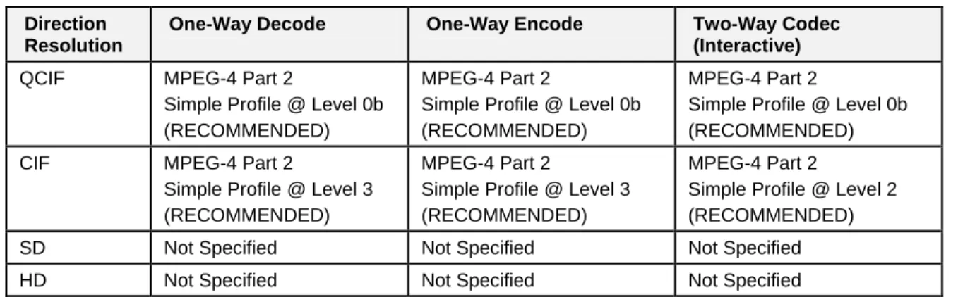
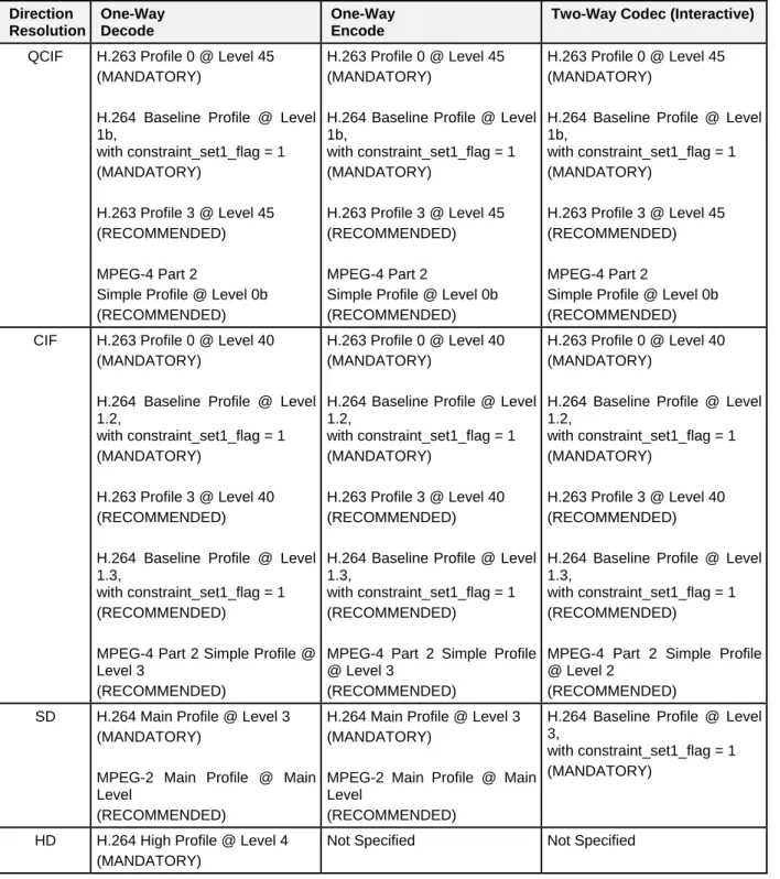
4.2.5.1.3 Media Handling
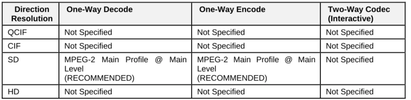
3GPP and 3GPP2 specify mandatory and recommended codecs to allow cellular video telephony and streaming with QCIF resolution (176 x 144), consistent with a cellular handsets’ small screen size and cellular networks' limited bandwidth_[TS 26.234] and_[TS 26.235]. Applicable codecs are defined in the list of codecs to be included in inter-operator agreements and to guarantee support at the NNI by the peer operators.
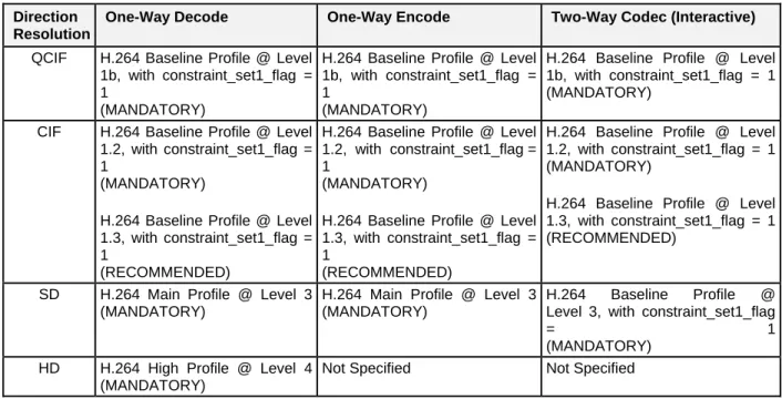
3GPP TS 26.114 specifies a client for the Multimedia Telephony Service for IMS (MTSI) supporting conversational speech, video, and text transported over RTP. As such, an MTSI client used for the delivery of video between end points will at least offer H.264 (AVC) Constrained Baseline Profile support at a level higher than Level 1.2.
4.2.5.2 GSMA
4.2.5.2.1 Session Establishment & Signaling
Conversational video services over LTE are specified in GSMA PRD IR.94. Video service clients
compliant with GSMA PRD IR.94 and conform to procedures defined in GSMA PRD IR.92 (VoLTE), and for interoperability and compatibility reasons indicate the capability to handle video calls by adding a “video” media feature tag to the Contact header field of the REGISTER request, as described in IETF RFC 3840.
31
4.2.5.2.2 Addressing & Routing
Conversational video services conform to addressing guidelines specified for IMS based multiparty services defined in GSMA PRD IR.65, which refers to procedures defined in 3GPP TS 23.228 and addresses formats defined in 3GPP TS 23.003.
Conversational video clients also conform to routing guidelines specified in GSMA PRD IR.65 requirements for routing between IMS networks as specified in 3GPP TS 29.165, and DNS query handling specified in GSMA PRD IR.67 to ensure end-to-end service interoperability.
4.2.5.2.3 Media Handling
The conversational video services over LTE comprise calls with full duplex voice and simplex/full-duplex video media with tight synchronization between the constituent streams. The call can be a point to point call or a multiparty conference call. The conversational video service over LTE can also be used to interact with dial-in video conference services, such as High-Definition Video Conference (HDVC), and based on procedures specified in GSMA PRD IR.39 (refer to section 5.10 – Video Conference/Collaboration in this document).
An IR.94 compliant client must indicate the capability to handle video calls (i.e., “video” media feature tag as described in IETF RFC 3840 and RFC 3841) and also include both voice and video media descriptors in the respective SDP offer as specified for Multimedia Telephony (MMTel) according to 3GPP TS 26.114.
IR.94 clients and the network must follow the voice media requirements and requirements on DTMF events as defined in GSMA PRD IR.92.
In addition, IR.94 compliant clients and the network must fulfill the requirements on supplementary services specified in GSMA PRD IR.92 and video media related additions, such as Coordination of Video Orientation (CVO) as specified in 3GPP TS 26.114. For CVO two (2) bits granularity are supported to terminate the user plane between UE and the entities in the IMS core network.
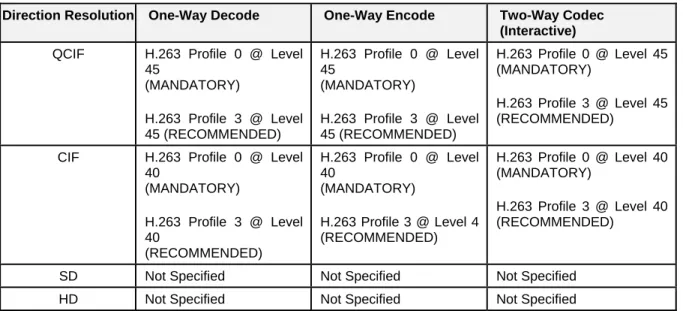
IR.94 clients and the IMS core network terminating the user plane must support of ITU-T Recommendation H.264 Constrained Baseline Profile (CBP) Level 1.2 as specified in 3GPP TS 26.114. Support of ITU-T Recommendation H.263 Profile 0 Level 45 as specified in 3GPP TS 26.114 is not required in the client.
Change of video resolution mid-stream by transmission of new parameter sets in the RTP media stream must be supported, as long as those parameter sets conform to the negotiated profile and level.
If due to certain circumstances video is removed, the conference shall be degraded to a voice only conference, or if the video conference can continue with the conference originator participating only using voice.
4.2.5.3 PacketCable
4.2.5.3.1 Session Establishment & Signaling
The PacketCable HD-voice session establishment and signaling gaps described in section Error! Reference source not found. generally apply to video as well. Video session establishment signaling for PacketCable 1.5 and PacketCable 2.0 is described in CODEC1.5-I04-120412 and PKT-SP-CODEC-MEDIA-C01-140314 respectively.