Automatic Gesture Recognition and Tracking System
for Physiotherapy
Aarthi Ravi
Electrical Engineering and Computer Sciences
University of California at Berkeley
Technical Report No. UCB/EECS-2013-112
http://www.eecs.berkeley.edu/Pubs/TechRpts/2013/EECS-2013-112.html
Copyright © 2013, by the author(s).
All rights reserved.
Permission to make digital or hard copies of all or part of this work for
personal or classroom use is granted without fee provided that copies are
not made or distributed for profit or commercial advantage and that copies
bear this notice and the full citation on the first page. To copy otherwise, to
republish, to post on servers or to redistribute to lists, requires prior specific
permission.
Automated Gesture Recognition and
Tracking System for Physiotherapy
Masters of Engineering 2012-2013
Capstone Project Report
Aarthi Ravi
SID 24090972
Contents
1. Abstract...2
2. Introduction...3
3. Literature Survey...3
4. Methodology...7
5. Results and Discussion...15
6. Conclusion and Future Work...24
7. References...25
1. Abstract
Physical Therapy is a branch of rehabilitative health that uses specially designed exer-cises and equipment to help patients regain or improve their physical abilities. Researchers have explored the use of software based rehabilitation tools based on video game consoles like Nintendo Wii Fit and Microsoft Kinect to provide remote rehabilitation facilities to patients. We propose a Kinect based Physical Therapy Application that guides pa-tients to perform exercises and assists therapists to monitor as well as teach the specially designed exercises to patients. The application includes an Automated Exercise Gener-ator for therapists to define exercises, an Automated Gesture Recognition and Tracking System to track and guide the patients while they perform the exercises and a Visual Feedback System for patients to correct the position and movement of their Joints. In this paper, we investigate how to enable continuous tracking of patients for pre-authored physiotherapy exercises. We introduce a state-machine-based approach that tracks a pa-tient’s progress and provides continuous feedback indicating whether the patient is doing an exercise correctly or not.
2. Introduction
The goal of Automated Gesture Recognition and Tracking System of our application is to track the users while they perform the pre-authored physiotherapy exercises and provide patients with incremental corrective feedback. Various ways of recognizing ges-tures using Spatial Gesture Models have been proposed in the past [1]. Spatial Gesture Models can be classified into 3D-Based Models and Appearance-Based Models [2]. The 3D-Model approach can use volumetric or skeletal models, or even a combination of the two. This approach is computationally very expensive. Appearance-Based Models use shape, surface reflectance, pose and illumination information for recognition. This ap-proach is easier to process but usually lacks the generality required for Human Computer Interaction. Our system uses a Skeleton-Based 3D Model for gesture recognition. Com-putational time is reduced significantly by using a Kinect Sensor. Using a Kinect depth
sensor offers the ability to use 3D depth information to facilitate real-time gesture track-ing. Moreover, for full-body gestures, human poses are inferred by the Kinect SDK using skeleton fitting so gestures can be authored based on skeleton configurations.
In this paper, we investigate how to enable continuous tracking for pre-authored physio-therapy exercises. This model is based on capturing key poses and interpolating between them to create motion trajectories. At exercise time, patients perform these exercises and the system tracks whether patients are doing this correctly. We introduce a state-machine-based approach that tracks a user’s progress through a motion segment.The state machine not only recognizes gestures but also recognizes transitions between gestures to avoid random transitions between gestures. The paper outlines how this is achieved. The first problem of recognizing Steps(or Gestures) of an Exercise is solved by checking the angles between certain Joints of a Skeleton as well as by checking the 3D positions of all Joints. The second problem of tracking the patient to see if he/she is following the right path between two consecutive Steps is solved by modelling the Joint Orientations as Quaternions. SLERP is then used to determine the intermediate orientations. The patient’s Skeleton is tracked and is identified to be following the right path as long as the Joint Orientations in the trajectory of movement match with the interpolated Joint Orientations.
3. Literature Review
This section elucidates the various approaches used in the past for Gesture Recognition using Kinect.
3.1 Gesture Recognition with Kinect using Hidden Markov
Mod-els
The method described by Jonathan Hall [3] uses a Markov chain or a Markov Model. It is a typical model for a stochastic sequence of a finite number of states. These states
are defined based on observations or data and these observations are essential for gesture recognition. In this approach, the observation data used are sequential 3D points (x, y, z) of Joints. A physical gesture can be understood as a Markov chain where the true states of the model S = s1, s2, s3,. . . , sN define the 3D position of Joints for each state. A gesture is recognized based on the states as well as the transition between these states. These states are hidden and hence this type of Markov model is called a Hidden Markov Model (HMM). At each state an output symbol O = o1, o2, o3,. . . , oM is emitted with some probability, and one state transitions to another with some probability. The emission and transition probabilities are learned while training the model with known gesture data and these values are stored in the emission and transition matrices. Each trained model can then be used to determine the probability with which a given gesture appears in test data. In the manner described above, trained HMMs can be used to recognize gestures.
Advantage: This method uses a skeleton-based gesture model and also takes transition between states into consideration.
Disadvantage: The true states of the model are defined by the user and hence is a supervised approach. The accuracy of the gesture model depends on the initialization of the states by the user. Erroneous input from the user could lead to poor performance. Thus, by averaging different sets of input states for the same gesture could solve this problem. This method does not provide corrective feedback to the user.
3.2 Gesture Service for the Kinect with the Windows SDK
Gesture Service for Kinect project in [4] considers gestures to be made up of parts. In our context, parts refer to key poses of an Exercise and gesture refers to a sequence of key poses or in other words the complete Exercise. Each part of a gesture is a specific movement that, when combined with other gesture parts, makes up the whole gesture. Recognizing gesture parts are not sufficient to recognize a gesture. This is due to the fact that transitions between gesture parts play a crucial role in a gesture. To incorporate transitions, the method considers three results that a gesture part can return when it
checks to see if it has been completed or not. The method uses a three-state approach for the gesture part to incorporate transitions. The state of the gesture part is set to “Fail” if the user moved in a way that was inconsistent with the gesture part. The state of the gesture part is set to “Succeed” if the user performed a part of the gesture correctly and the system will automatically check for the next part of the gesture. Finally, the state of the gesture part is set to “Pausing” if the user is transitioning to the next gesture part. It indicates that the user did not fail the gesture but did not perform the next part either. The system would check for this part after a short pause. Pausing allows the system to identify a movement that does not fulfill the gesture but could be a result of the user moving slowly. The overall system comprises of three classes, namely, gesture controller, gesture and gesture part. The method uses a Gesture Controller to control the transition between gesture parts and updates the state of the gesture part.
Advantage: This method uses a skeleton based gesture model.
Disadvantage: Though this method tries to incorporate transitions, it is not efficient unless we consider a large number of gesture parts that are infinitesimally close to each other.
3.3 Kinect Space
The Kinetic Space described in [5] provides a tool which allows everybody to record and automatically recognize customized gestures using the depth images and skeleton data as provided by the Kinect sensors. This method is very similar to the Hidden Markov Model [3] as discussed before. The software observes and comprehends the user interaction by processing the skeleton of the user. The unique analysis routines allow to not only detect simple gestures such as pushing, clicking, forming a circle or waving, but also to recognize more complicated gestures as, for instance, used in dance performances or sign language. In addition it provides a visual feedback how good individual body parts resemble a given gesture. The system can be easily trained for recognizing a gesture easily without writing any code. The gesture recognition software developed is independent of the person training the system as well as independent of the orientation and speed of the
user training the system. The software has already been used by media artists, dancers and alike to connect and to control a wide range of third party applications/software such as Max/MSP, Pure Data etc.
Advantage: This method uses a skeleton based gesture model and also takes transition between states into consideration. No code has to be written by the trainer.
Disadvantage: This method does not consider breaking a gesture into segments or parts and as a result a large amount of data is used to describe a gesture making it a memory inefficient solution. By considering gesture segments and interpolating them would result in a more memory efficient solution.
3.4 Kinect SDK Dynamic Time Warping (DTW) Gesture
Recog-nition
The project described in [6] allows developers to include fast, reliable and highly customiz-able gesture recognition in Microsoft Kinect SDK C-sharp projects. It uses Dynamic time warping (DTW) [7] algorithm for measuring similarity between two sequences which may vary in time or speed. It uses skeletal tracking but the drawback with this software is that it currently supports only 2D vectors and not 3D. The software includes a gesture recorder that records the user’s skeleton and trains the system. The recognizer software then recognizes the gestures that have been trained by the user.
Advantage: This method uses a skeleton based gesture model.
Disadvantage: This method supports only 2D and not 3D vectors. It does not track whether a user is correctly following a trajectory between poses. It does not give incre-mental feedback along the way.
3.5 Hand gesture recognition using Kinect
A novel method for contact-less Hand Gesture Recognition using Microsoft Kinect for Xbox has been described in [8]. The system can detect the presence of gestures, to identify fingers, and to recognize the meanings of nine gestures in a pre-defined Popular Gesture scenario. The accuracy of the system is from 84 percent to 99 percent with
single-hand gestures. Because the depth sensor of Kinect is an infrared camera, the lighting conditions, signers’ skin colors and clothing, and background have little impact on the performance of this system.
Advantage: This method has a good accuracy rate.
Disadvantage: This method is limited to Hand Gestures.
Kinect Space project described in 3.3 provides an effective interaction technique to record gestures. This is ideally suitable to a therapist as he/she can record the Exercises by easily demonstrating the Exercises and they are not expected to do any program-ming. However, supervised learning could introduce outliers in the Exercise definition. To overcome this we average the training data by making the trainer record the Exercise multiple times and discard outliers. On the patient side, none of the applications provide an incremental corrective feedback to the user so that he/she can rectify his/her mistakes. By using the state-machine-based approach described in HMM Model and Gesture Ser-vice method we can incorporate a model to continuously track patients while they are performing the Exercises. The model is based on capturing key poses of an Exercise in a XML file and interpolating the Joint Orientations of key poses to create motion tra-jectories. At Exercise time, the state-machine checks to see if the user is performing the Exercises correctly. This is done by comparing the Joint Orientation of the user obtained from the live feed with the interpolated Joint Orientations. The following sections explain our novel technique in detail.
4. Methodology
This section elucidates the proposed State Machine Design for our Kinect-based Physio-therapy Application. The State Machine has been designed to solve two problems- first, to recognize Steps of an Exercise as defined by the trainer and second, to track the tran-sitions between these Steps to ensure the patient/user of the application is following the right path. The ability to monitor transitions between Steps provides the Application with a way to assist the patients in providing valuable feedback by indicating the exact
mistakes to the user. The following sub sections provide a detailed understanding of the relevant data from the Kinect and a comprehensive description of the State Machine.
4.1 Understanding Relevant Kinect Data
Kinect Joints
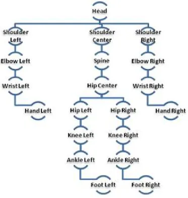
The Skeletal Tracking System of the Kinect tracks 20 Joints [9] of the human in the default standing position. Figure 1 shows the different Joints tracked by the Kinect [10]. The Kinect provides us with 3D information of these Joints.
Figure 1: Kinect Joints
Bone Hierarchy
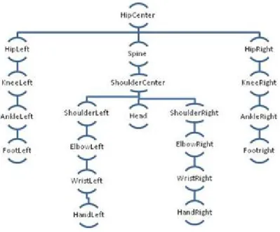
The Kinect defines a hierarchy of bones using the Joints defined by the Skeletal Tracking System as described in [11]. The hierarchy has the Hip Center Joint as the root. The Bone Hierarchy diagram is shown in Figure 2. The Kinect provides the bone orientation in two forms:
•A hierarchical rotation based on a bone relationship defined on the skeleton Joint struc-ture
Figure 2: Bone Hierarchy
• An absolute orientation in Kinect camera coordinates
The orientation information is provided in form of quaternions and rotation matrices.
For our problem, we use the bone orientation information in the form of hierarchical rotations specified using quaternions. Hierarchical rotation provides the amount of rota-tion in 3D space from the parent bone to the child. This informarota-tion tells us how much we need to rotate in 3D space the direction of the bone relative to the parent. This is equivalent to considering the rotation of the reference Cartesian axis in the parent-bone object space to the child-bone object space, considering that the bone lies on the y-axis of its object space. The orientation information provided includes the Start and End Joint information of the bone as well.
4.2 Pre-processing - Loading XML file
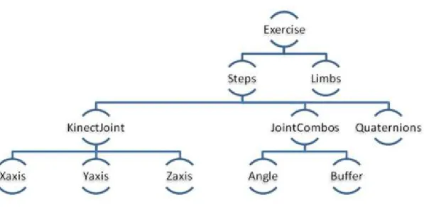
The Exercise definition is stored in an XML file. The Exercise definition is as shown in Figure 3. For each Step, the XML file contains 3D co-ordinates of each Joint centered at the Hip Center, the Joint Angles formed by adjacent bones, the quaternions representing Joint Orientations and the Limb lengths.
Figure 3: Exercise Definition
loaded. The following classes are defined to store the defined components of an Exercise.
Joint Class: Stores the Joint Name, Joint Type, X,Y and Z co-ordinate values centred at the HipCenter Joint of the Skeleton
JointCombos Class: Stores the Joint Combo Name and the angle between the bones defined by these Joints
Steps Class: Stores Step Id, number of Joint objects, number of JointCombos, number of Quaternions, List of Joint objects, List of JointCombo objects and a List of Vector4 objects containing Quaternion Data for each Joint providing the hierarchical rotation from the parent bone to the child in the form of Quaternions
Exercise Class: Stores the Exercise name, number of Steps in the Exercise and a List of Steps objects
4.3 State Machine Overview
The first problem of recognizing Steps(or Gestures) of an Exercise is solved by checking the angles between various Joints of a Skeleton as described in Appendix A-1 as well as by checking the 3D positions of the Joints centred at the Hip Center Joint. The Joints in the Skeleton are as shown in the Figure 1.
The second problem of tracking whether the patient/user is following the right path be-tween two consecutive Steps is solved by modelling the Joint Orientations as Quaternions. This theory is used popularly in Skeletal Animation to animate between key frames as described in [12] and [13]. Comparing our problem with the Skeletal Animation problem, it can be seen that the Joint Orientations of each Step in the Exercise can be consid-ered as a key frame and by interpolating between these key frames we can accurately determine the Joint Orientations of intermediate frames. Quaternions have been used extensively in skeleton animations as it solves a crucial problem of gimbal locks that exist while modelling rotations as Euler Angles and a good comparison between these two methods can be seen in Micheal Johnson’s Doctrate Thesis [14] and practical ap-plication of this method is well described in the articles [15], [16] and [17]. A Spherical Linear Interpolation(SLERP) is performed to smoothly interpolate these orientations to determine the intermediate Joint Orientations between the consecutive Steps of an Exer-cise. By polling the Skeleton Frame at regular intervals, the transition between Steps(or Gestures) is tracked and the user is identified to be following the right path as long as the Joint Orientations in the trajectory of movement match with the interpolated Joint Orientations.
4.4 State Machine Design
4.4.1 Exercise Manager
The Exercise Manager assists in controlling the smooth flow of control between states and updating state data. It comprises of two main components the ExerciseState and Gesture Controller.
Exercise State: The state of the State Machine is stored in an ExerciseState object. It stores the Current Exercise Number, the state of the Step and List of QuaternionsAt-Steps objects which contain a List of Hierarchical Rotations from parent bone to child at each Joint (as explained in the previous section).
states for the Gesture: • gestureNotStarted • gestureNotInProgress • gestureStarted • gestureInProgress • gestureEnd
Gesture Controller: We define a Gesture Controller object which checks and mod-ifies the State of the Gesture. When a Skeleton Frame is generated we pass it to the updateGestureState method of the Gesture Controller which updates the State based on a few checks explained later.
4.4.2 State Machine Work Flow
The Exercise Manger passes the Skeleton Frame to the Gesture Controller every time a Frame is generated. The Gesture Controller performs two checks. First, it checks if the Angles between the various Joints as specified by the JointCombo objects are sat-isfied. The next check it performs is to see if the 3D points of the current Skeleton Frame centred at the Hip Center Joint matches with those defined in the Exercise def-inition. Note,both these checks are performed by considering some buffers defined by
T HRESHOLDS AN GLE and T HRESHOLDS 3DP OIN T S respectively.
If both the checks are satisfied then the Gesture, in our case a Step, has been recog-nized. The Exercise state is modified to gestureStarted and the currentStep is updated to the next Step. If either of the checks is not satisfied then we do not modify the Exre-ciseState and it remains as gestureNotStarted.
After the checks are completed we take certain actions based on the Exercise State.
If the ExerciseState is gestureNotStarted, gestureNotInProgress or gestureEnd we do nothing.
the Step that was just recognized and that of the next Step are computed. The Quater-nions at each Joint of each Step indicate the hierarchical rotation needed to rotate the parent bone to the child. The interpolated Quaternions at each Joint are computed using SLERP [18] as shown in (1).
q = q1 sin((1−t)θ) +q2 sin(tθ)
sinθ (1)
where:
• q = interpolated quaternion
• q1 = first quaternion to be interpolated between
• q2 = second quaternion to be interpolated between
• t = a scalar between 0.0 (at q1) and 1.0 (at q2)
• θ = half the angle between q1 and q2
If the ExerciseState is gestureInProgress then a check is performed to see if the Joints are following the right path between the Steps in an Exercise. This is performed by computing the Quaternion distances between each Joint in the current frame to each Joint of an interpolated frame. The quaternion distances between the current orientation and the orientation specified by the interpolated orientations can be computed as an angle of rotation θ [19] required to get from one orientation to another and is computed using the formula shown in (2).
θ= arccos (2(q1·q2)2−1) (2)
where q1.q2 denotes the inner product of the corresponding quaternions.
We find the sum of squares of these distances of all Joints of the current frame with all the Joints of the interpolated frame and repeat it for all the interpolated frames.
θavg = v u u t N X i=1 θ2 i (3) where:
N = Number of Kinect Joints
θi = Angular Distance between Joint Orientation of the i’th Joint of the current frame
and interpolated frame.
The interpolated frame closest to the current frame is determined by comparing these distances for each interpolated frame. The angle distances between the quaternions of each Joint of the current frame and the quaternions of each Joint of the interpolated frame are compared with a T HRESHOLD AV ERAGE. Those Joints with angle distances greater than this threshold are identified as the Joints which are not following the right path and the others are identified as following the right path.
Feedback
We provide incremental corrective feedback to the patient to keep him/her on the correct trajectory of movement. If the Joint Orientation of a given Joint in the Skeleton Frame of the user differs from the Joint Orientation of the same Joint in the interpolated Frame by more thanT HRESHOLD AV ERAGEthen the Child Bone from the Joint is considered to be at a wrong position. This is incrementally indicated to the user by displaying wrong Bones as Yellow/Red. Red indicates the Bone which has deviated the most amongst all Bones. To provide a better feedback we render 3D arrows in a 2D display showing in which direction the Bone marked in Red should be moved. Inorder to provide this feedback, we first convert all Hierarchical Rotations to Absolute Rotations. This can be computed by multiplying all the Hierarchical Rotation Quaternions of Joints in the Hierarchical Tree path(as shown in Figure 2) starting from the Hip Center to any given Joint. These Absolute Rotations are in the form of Quaternions and need to be Converted into Euler Angle Notation. We then compute ∆x, ∆y and ∆z. These represent amount of rotation in x, y and z axes by which the incorrect bone must rotate inorder to match correct trajectory of movement. We consider a rotation about an axis only if the ∆ change is above a threshold. This results in a large number of arrow orientations to handle all possible cases.
5. Results and Discussion
5.1 Exercises used for Training and Testing
We tested the Gesture Recognition and Tracking module with five Exercises.
1. Military Press
2. External Arm Raise
3. Left Arm 90 External Rotation
4. Arm Curl
5. Right Leg Extension
5.1.1 Military Press
Step 1 Step 2 Step 3
5.1.2 External Arm Raise
Step 1 Step 2 Step 3
5.1.3 Left Arm 90 Degree External Rotation
Step 1 Step 2 Step 3
5.1.4 Arm Curl
Step 1 Step 2 Step 3
5.1.5 Right Leg Extension
Step 1 Step 2 Step 3
5.2 Gesture/Step Recognition Testing
Our Application checks to see if the Target Step has been completed. The tests were run for the 5 Exercises defined in the previous section. At every Skeleton Frame generated by the Kinect, the angles between different Joint combinations were compared to the values specified in the XML file. The 3D positions of the current Skeleton Frame were also compared with the positions specified in the XML file. The Application recognizes all the Steps of the 5 Exercises described in the previous section. The Exercise definition also included threshold parameters that were designed to allow for margins of error in the Exercise Steps. The thresholds used for this module includeT HRESHOLD AN GLE = 10◦ andT HRESHOLD 3DP OIN T = 0.2mThese were low thresholds and worked well for all the Exercises.
5.2 Testing of Exercise Tracking Module
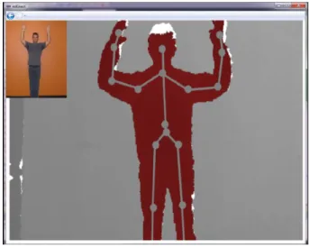
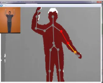
Our Application also checks to see if the patient is following the correct trajectory between consecutive Steps of an Exercise and prevents random transitions between Steps of an Exercise. The UI of our Kinect Physiotherapy Application is shown in Figure 4. The image of the therapist on the top left hand corner displays the Target Step that the patient has to move to from the Previous Step. The live Depth Stream is displayed with the Skeleton drawn over the Depth Frame. The Bones are shaded in grey and the Joints
are indicated using grey circles as shown in the Figure. A Bone is color coded as Gray if the Bone is in the correct position with respect to its Parent Bone and Yellow if the bone is not in the right position with respect to its Parent Bone. The Bone which has deviated the most from the threshold amongst the wrong Bones(indicated by Yellow) is color coded with Red.
Figure 4: FrontEnd of GUI
Bones in the Right Orientation
All bones are in the right orientation. Thus, all the circles have to be color coded with Green. This Case has been shown in Figure 4.
Bones are not oriented correctly
Some bones are not oriented in the right direction with respect to its parent bone. This Case has been shown in Figure 5. It can be seen that the bone from Shoulder Left Joint to Elbow Left Joint and the bone from the Elbow Left Joint to the Wrist Left Joint are way off from the actual path. Therefore, these bones have been color coded as Red and Yellow to indicate to the patient that he is not following the right path and the Sholuder Left-Elbow Left Bone is most off and is indicated using Red.
Figure 5: Errors in the Bone Orientation with respect to the Parent
Intermediate Bones are incorrectly oriented
Only Intermediate Bones are not oriented correctly. This Case is shown in Figure 6.The bone from Elbow Left Joint to the Shoulder Left Joint is not oriented in the right direction with respect to its parent bone which is the bone from Shoulder Left Joint to the Shoulder Center Joint. Hence, this bone has been color coded with Red(indicating most incorrect bone). The same is true for Right side of the Skeleton as well. But, the bone from the Elbow Left Joint to Wrist Left Joint are at the right orientation with respect to its parent bone which is the bone from Elbow Left Joint to Shoulder Left Joint. Thus, the bone has been color coded with Gray.
Arrow Feedback
We provide corrective feedback to the users by embedding a 3D arrow into 2D display and indicating to the user in which direction he should move a specific bone. This has been illustrated in Figure 7 and Figure 8. The Red Arrow at the bottom indicates in which direction the user should move the Bone indicated by Red for him/her to move along the right trajectory.
Figure 7: Arrow Feedback
5.2.3 Observations on Changing Parameters
Parameter- Thresholds/Buffers
Observation: Setting thresholds/choosing buffer sizes is crucial for this kind of an appli-cation as this determines the amount you allow users to deviate from the actual trajectory.
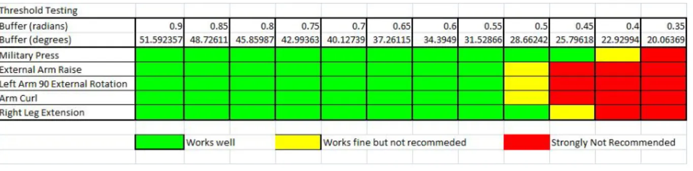
Reason: Enforcing the user to strictly follow the path would discourage the users to use this application and at the same time by using large buffers the patients may deviate a lot from the right path of transition between Steps. We conducted a Pilot Study with 5 users of different physic to study the user experience by changingT HRESHOLD AV ERAGE
values. The results are shown in Table 1. We observe that a value 0.55 radians as thresh-old for T HRESHOLD AV ERAGE gives a good user experience for all the Exercises tested on all the users. Regions marked in Green indicate these thresholds provide a good experience to the users. Regions marked in Yellow indicate these thresholds worked well for some but not well for others. Lastly, regions marked in Red indicate these thresholds produced a bad user experience to all the users.
Table 1: Threshold Testing
Parameter: Number of Steps for a specific Exercise
Observation: Defining more Steps for a specific Exercise increases the Accuracy
Reason: If the next Step is very different from the current Step the interpolated quater-nions would be far apart. In such cases it is recommended that we define more Steps so that the interpolated points are not very far part.
Parameter: Number of Interpolation Points
Observation:Increasing Number of Interpolation Points increases Accuracy but also introduces a lag in the feedback
Reason: Increasing the number of interpolated points ensures that the points computed are not too far apart thus producing an accurate set of interpolated points. But this increases the nearest neighbour computation time. Keeping in mind this trade-off, we observed that 1000 interpolation points works good with no lag in feedback.
Table 2: Interpolation Testing
Parameter: Number of Skeletal Frames Polled
Observation: Polling Skeletal Frames at short regular intervals instead of every Skeletal Frame generated doesn’t affect our results and reduces computations significantly
Reason: 12 Skeleton Frames are produced every second. The human visual system can-not differentiate much between these frames. Thus, dropping frames in between doesn’t affect the feedback given to the user and moreover these frames are so closely related to each other that it doesn’t affect our results.
6. Conclusion and Future Work
Using the State Machine Design described in this paper Automatic Gesture Recognition and Tracking of Exercises can be performed with very high accuracy and at real time. The State Machine can not only recognize Steps of an Exercise but can also recognize the correct path of transition between Steps. Most importantly, the State Machine pro-vides incremental corrective feedback to the patient. Thresholds play a very vital role in specifying the deviation allowed. Thresholds with valuesT HRESHOLD AV ERAGE = 0.5radians,T HRESHOLD AN GLE = 10degreesandT HRESHOLD 3DP OIN T S = 0.2m works well for all the Exercises that were tested.
The method proposed in this paper assumes that the trainer and the patient have similar physical structure. But, this might not be true at all times. This problem can be solved by solving the problem of Re-targeting. [20] describes many solutions to the problem of Re-targeting. A naive method would be to use the Limb Lengths of per-sons(already stored in the XML file) to adjust the 3D positions of Joints. The method proposed uses a number of thresholds. This method can be further enhanced by learn-ing these thresholds durlearn-ing trainlearn-ing time by recordlearn-ing multiple instances of an Exercise, averaging out the thresholds and multiplying the thresholds by a safety factor.
References
[1] “Gesture recognition,” Wikipedia. [Online]. Available: http://en.wikipedia.org/ wiki/Gesture recognition
[2] T. S. H. Vladimir I. Pavlovic, Rajeev Sharma, “Visual interpretation of hand ges-tures for human-computer interaction,”IEEE Transactions on Pattern Analysis and Machine Intelligence, 1997.
[3] J. Hall, “How to do gesture recognition using kinect with hidden markov models (hmms),” CreativeDistraction, 2011.
[4] “Gesture service for the kinect with the windows sdk,” MCS UK Solution Develop-ment, 2011.
[5] M. Woefel, “Kinect space,” Google COde, 2012.
[6] “Kinect sdk dynamic time warping(dtw) gesture recognition,” CodePlex, 2011. [7] “Dynamic time warping(dtw),” Wikipedia. [Online]. Available: http://en.wikipedia.
org/wiki/Dynamic time warping
[8] Y. Li, “Hand gesture recognition using kinect,” inIEEE 3rd International Conference
on Software Engineering and Service Science (ICSESS), 2012.
[9] “Joints tracked in default mode,” MSDN. [Online]. Available: http://msdn. microsoft.com/en-us/library/hh973077.aspx
[10] “Joint type enumeration,” MSDN. [Online]. Available: http://msdn.microsoft.com/ en-us/library/microsoft.kinect.jointtype.aspx
[11] “Joint orientation,” MSDN. [Online]. Available: http://msdn.microsoft.com/en-us/ library/hh973073.aspx
[12] X. Y. Xiaolong Tong, Pin Xu, “Research on skeleton animation motion data based on kinect,” 2012 Fifth International Symposium on Computational Intelligence and
Design (ISCID), 2012.
[13] Z. T. J. L. Chen Hong, Shuangjiu Xiao, “Real-time motion recognition based on skeleton animation,”2012 5th International Congress on Image and Signal Process-ing (CISP), 2012.
[14] M. P. Johnson, “Exploiting quaternions to support expressive interactive character motion,” Ph.D. dissertation, MIT, 1995. [Online]. Available: http: //pubs.media.mit.edu/pubs/papers/johnson phd.pdf
[15] “Understand skeletons,” UCSD. [Online]. Available: http://graphics.ucsd.edu/ courses/cse169 w05/2-Skeleton.htm
[16] “3d skeletal animation,” 3DKingdoms. [Online]. Available: http://www. 3dkingdoms.com/weekly/weekly.php?a=4
[17] “Skeletal animation,” HIOF. [Online]. Available: http://www.it.hiof.no/∼borres/
[18] K. Shoemake, “Animating rotation with quaternion curves,”SIGGraph ’85 proceed-ings, 1985.
[19] “Quaternion distances,” Math Stack Exchange. [Online]. Available: http: //math.stackexchange.com/questions/90081/quaternion-distance
[20] K. P. M. T. N. G. Daniel Vaqueroa, Matthew Turka, “A survey of image retargeting techniques,” Applications of Digital Image. Processing XXXIII, Proc. SPIE (2010). [Online]. Available: http://people.csail.mit.edu/kapu/papers/VaqueroSPIE10.pdf
Appendix A
1. Joint Combinations: 16 Joint combinations were defined based on the Joints detected by the Kinect. Each Joint combination is made up of 3 Joints which can be interpreted as 2 vectors with a common origin. The angle in between these vectors is the angle used in the JointCombo section of the Exercise definition. The class that defines these 16 combinations can be seen below:
public static class JointCombinations
{ //s shoulder //e elbow //w wrist //sc shoulder center //head head
//hipc hip center //h hip //a ankle //k knee //f foot //l left //r right
public const stringw e s l= ”w e s l”; public const stringw e s r = ”w e s r”; public const stringe s sc l = ”e s sc l”; public const stringe s sc r = ”e s sc r”;
public const strings sc head l = ”s sc head l”; public const strings sc head r = ”s sc head r”; public const strings sc hipc l = ”s sc hipc l”; public const strings sc hipc r = ”s sc hipc r”; public const stringsc hipc h l= ”sc hipc h l”; public const stringsc hipc h r = ”sc hipc h r”; public const stringhipc h k l= ”hipc h k l”; public const stringhipc h k r = ”hipc h k r”; public const stringh k a r = ”h k a r”; public const stringh k a l = ”h k a l”; public const stringk a f l = ”k a f l”; public const stringk a f r = ”k a f r”;}