An Incrementally Scalable Multiprocessor Interconnection Network with
Flexible Topology and Low-Cost Distributed Switching.
Ronald Pose, Vincent Fazio, Jon Wells
Department of Computer Science, Monash University, Clayton, Victoria 3168,
AUSTRALIA rdp@cs.monash.edu.au
Abstract
Massively parallel computing architectures are becoming widely accepted in many computationally intensive areas. One of the prime advantages touted is their scalability, and yet while in principle a good degree of scalability is possible, in practice the unit of scaling is very coarse. The net effect of this is to make incremental expansion of such machines impractical except for large and expensive expansion to multiples of the original size and in some cases expansion by powers of two is required. In this paper a multiprocessor interconnection scheme with low fixed overheads and linear incremental scaling costs is described.
1. Introduction
When performance limitations of conventional single processor computer systems first encouraged people to integrate a number of processors and memories into a single system the approach taken was to use either a shared memory bus or a switch interconnecting processors and memories. A shared bus provides a very cheap and simple interconnection scheme but can become saturated and lose performance with only a moderate number of processors. Switch based interconnects are much more expensive and can have high performance but are even more limited in the number of processors which can be attached directly. Various hierarchies and networks of switches have been employed in attempts to scale the systems beyond the capacity of a single switch or bus. Hence was born the idea of a massively parallel computing system with hundreds or thousands of processors interconnected either with a shared memory structure or via a structure which allows messages to be routed between the processors.
Massively parallel computing architectures are becoming widely accepted in many computationally intensive areas. One of the prime advantages touted is their scalability, and yet while in principle a good degree of scalability is possible, in practice the unit of scaling is very coarse. The net effect of this is to make incremental expansion of such machines impractical except for large and expensive expansion to multiples of the original size and in some cases expansion by powers of two is required.
The main problem with scaling these machines to larger and larger configurations is the nature of the interconnection network. In order to get the bandwidth required to make effective use of the machine significant resources are dedicated to the interconnection network. The interconnection network tends to involve the majority of the circuitry and the cost of current massively parallel computer systems. It also tends to be built out of large switching units. Given the relative costs of the switching units and the processors, it is not cost-effective to obtain a machine with fewer than the number of processors required to occupy a switching unit. The unit of scalability is thus this number of processors at best, and depending on the switching topology may require exponential growth patterns to make effective use of the switching investment. While it may seem reasonable to go from a 4 node system to an 8 node system, when it comes to expansion granularity much coarser than this as is becoming common, the incremental costs become prohibitive. One has to find the money in large amounts rather than by expanding the system gradually as needs and finances permit.
We propose an architecture and interconnection topology which distributes the switching investment uniformly across the nodes of the system. It is thus scalable from a single processor-memory node up to over a thousand nodes in increments of single nodes. The architecture has been developed from the beginning with incremental scalability in mind. Engineering aspects of the implementation of the architecture have been considered at all levels so as to keep the cost of the system down and to make the system practical to build. The commercial potential of the architecture is also a factor in its design. The interconnection mechanisms are designed to be fairly independent of the processor technology being used. The system is in fact designed not only for incremental expansion but also for incremental upgrading to the latest fastest processors without discarding the existing processors.
2. Nodes
The basic node in the architecture is a combined processor-memory-switching element. There is only a single kind of node in the system. In fact there are no other active components in the system. The interconnection topology is implemented entirely through low cost passive interconnections between the nodes. A variety of interconnection topologies is possible with this approach with different performance tradeoffs.
The node comprises a number of subsystems including at least one processor unit, at least one memory unit, two parallel bus ports, a high speed serial connection and a switching scheme to route traffic between these elements. The processor unit can read and write the local memory unit and can direct memory references to memory units on other nodes through
the bus ports or the fast serial link. The memory units can accept operations from the local processor unit, or from either bus port or the fast serial link. Facilities are also available to allow a processor to instruct a memory unit to copy data into another memory unit in a different node. The switching hardware handles the routing between these elements and indirectly through the larger interconnection topology. In effect the system functions as a distributed shared memory with a non-uniform access time. A node is depicted in figure 1.
Processor Unit Processor Unit Memory Unit Switch Memory Unit Bus I/F Unit Bus I/F Unit High Speed Serial Link
Bus Ghz Links Bus
Node
Figure 1. Structure of a Node
additional back-to-back connection points to convert cylindrical
into spherical topology
Figure 2. Planar 4 node per bus topology
Node Bus c c c c s s s s c additional back-to-back connection points to convert planar
into cylindrical topology
s
additional back-to-back connection points to convert cylindrical
into spherical topology
Because there is only a single type of node the system is well suited to economical commercial mass production. A single node contains memory and processor on a single board and could form the basis for a conventional workstation-style computer sitting on someone's desk. A slightly larger system with a moderate number of nodes can sit in the corner of the room. A large system with over a thousand nodes could live in a machine room. Identical boards are used in each and extra boards may be added one at a time.
2.1 The Processor Unit
A node may contain one or more processor units. While a processor unit typically is based on a 64-bit RISC microprocessor, the only real requirements are that it be a device which can generate addresses and data and accept data it may have requested. The communication protocol and mechanism used has to be consistent with that employed by other units in the node but need not be identical on every node. A processor unit may be implemented as a plug in module or daughter board to allow for easy maintenance and future upgrades.
Typically a processor unit is matched in speed and technology with the memory units in the same node however this is not essential as long as reliable communication is achieved. It is to be expected that modern high speed processor units will contain appropriate caches to minimize the impact of memory latency and to minimize the amount of memory traffic.
2.2 The Memory Unit
A node may contain one or more memory units. A memory unit typically will comprise a memory array, associated error detection and correction and control logic, and a controlling device which can be instructed to copy a block of data to another memory unit via one of the bus interfaces or over the high speed serial link. Obviously it must also be able to accept such a block of data from a bus interface.
In a node equipped with processor units based on modern 64-bit RISC technology, it would be expected that a memory unit would contain at least 64 Mbytes of memory. Logically though it must be a module which accepts an address, a function and perhaps some data, and may if required return some data. It must be able to communicate with both the bus interfaces and serial link and with the processor units on the node. As with processor units, a memory unit may be implemented as a plug in module or daughter board so as to allow upgrading to higher performance or larger memory sizes.
2.3 External Communications Interfaces
While a processor unit and a memory unit together make up a node which is the equivalent of a modern single board computer, the aim of this system is to allow such machines to be scaled into large multiprocessor systems. For this to be achieved there has to be a means of communicating between nodes. Two different kinds of external communications interfaces have been devised for this purpose. Reasons for having both mechanisms are discussed in the engineering section.
Two bus interfaces are provided on each node. These are 64-bit parallel bus interfaces with associated control logic and an implementation of a two level communication protocol for communicating with other nodes. The other end of the bus interface communicates with all the other units in the node, including the other bus interface and the high speed serial link. It is expected that large buffers would be included in the bus interface. These could act as a kind of write buffer for the other units allowing them perhaps to continue with other activities while internode transfers are taking place.
Another key feature is that there is no common clock in the system as a whole. Our design philosophy of a single kind of active node interconnected passively precluded the conventional centralized clock distribution approach which anyway is
rather difficult to implement in a large scale system. Each node runs at its own speed. This avoids a major clock distribution problem and allows upgrading to faster nodes on an individual basis rather than having to upgrade the whole system. It also means that each bus interface transmits data using its own clock since no other clock is available. By transmitting the clock along with the data bus interfaces can receive data using the clock at which it was transmitted. An architecture employing FIFOs as both buffering elements and synchronization elements has been devised (Castro & Pose 94).
The high speed serial link performs the same function as the bus interface units in that it allows units to communicate with units in other nodes. The technology employed in the high speed serial link is quite different. Instead of being based on a 64-bit parallel bus, the external interface of the high speed serial link is a pair of unidirectional 1 GHz serial connections over coaxial cable or fibre optic cables. Even at 1 GHz this link will be slower than the 64-bit parallel interfaces which could run at over 50 MHz, however the technology employed allows for different physical arrangements of the system as will be discussed later.
2.4 Switching within a Node
The key to our approach is that the switching component which dominates the traditional massively parallel machine has been distributed equally across all nodes and is a moderate overhead on each board which can even be ignored for a single node workstation.
The various units making up a node indeed need to communicate with one another. Because there are only a small number of units in a node it is not necessary to invest in large scale expensive switching apparatus. It is wise however to allow each of the units to operate to its capacity so a single bus interconnecting all the units is not appropriate. At the other extreme a small cross-bar switch interconnecting the units is unnecessary although not too unreasonable given the small number of units. A good performance tradeoff can be achieved by employing a small number of buses which allow the most heavily used inter-unit communications to proceed concurrently.
3. Interconnection Network Topology
The node forms a simple building block from which one can construct large systems interconnected in a variety of topologies. Given that the off-node interconnection hardware has to be passive to preserve our goal of a single active component type, and that it must be possible to have practical implementations from the engineering viewpoint, we have devised a scheme which allows 6 different topologies to be implemented with differing characteristics.
3.1 Planar Topology with 4 Nodes per Bus
In this topology each node is connected to two buses, one for each bus interface. Every bus in the system has a maximum of 4 nodes on it. Remember that buses are just a passive set of parallel wires. A planar topology with 4 nodes per bus is depicted in figure 2.
3.2 Cylindrical Topology with 4 Nodes per Bus
While it is indeed possible for any node in the system to communicate with any other node by passing data through intermediate nodes it is clear that the path length and hence the communication time will be non-uniform. It is possible to reduce the maximum path length by rolling the plane into a cylinder. For instance if one examines the planar topology depicted in figure 2 one will see that there are buses on the left and right ends of the plane which have only 2 nodes on them. Logically one may combine these buses into single buses with 4 nodes each. This may be likened to rolling the plane into a vertical cylinder but is better realized from the engineering standpoint by producing a flattened cylinder by placing two smaller planar backplanes back-to-back.
3.3 Spherical Topology with 4 Nodes per Bus
Just as the observation was made that the left and right ends of the planar topology were not fully populated, it is also evident that some buses at the top and bottom of the planar topology and the cylindrical topology are also not fully occupied. Logically these may also be combined by folding in the other direction and you actually end up with a kind of spherical topology. This also works out very well from the engineering viewpoint in that the back-to-back flattened cylinder construction also has the appropriate under occupied buses for a flattened sphere located back-to-back allowing a simple interconnection to combine them. For a given number of nodes a spherical topology has a shorter average path length than a cylinder, which itself has a shorter path length than a planar topology.
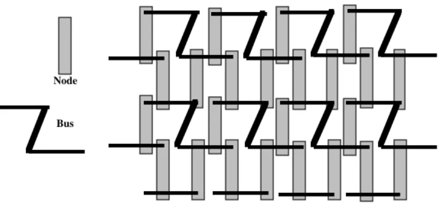
3.4 Topologies with 6 Nodes per Bus
While we indeed have reduced the maximum and average path lengths between nodes in going from a planar topology to a cylindrical one to a spherical one, it is possible to further reduce the average path length by increasing the number of nodes per bus. By doing this one needs fewer buses for a given number of nodes. Of course one increases the traffic on each bus by doing this. A planar topology with 6 nodes per bus is depicted in figure 3.
Note that while this topology can also be connected into cylindrical and spherical arrangements, due to the asymmetrical bus shape one can get different numbers of nodes per bus around the edges of the backplane. It is even possible to end up with 8 nodes on some edge buses but this can be avoided by removing a node.
Figure 3. Planar 6 node per bus topology
Node
Bus
Note that this depiction of a 6 nodes per bus topology indicates that the buses are bent. It is useful to employ such buses in our system since we do not want to violate our design principle of a single kind of node, and by arranging bent buses we can plug in nodes identical with those used in the 4 nodes per bus systems. It is also very convenient from the engineering perspective to use such bent buses. Careful comparison of figures 2 and 3 reveal that the vertical parts of the buses in figure 3 correspond to nodes in figure 2. In fact one can take the identical backplane structure that was used for the 4 nodes per bus topology and just replace every second node board with a passive set of wires linking the two buses. This may be achieved with a dummy node board only containing wires with no active components.
Just as in the case of topologies with 4 nodes per bus, it is also possible to fold the plane into a cylinder or sphere. In fact the identical structure of back-to-back backplanes can be employed. All six topologies may be created from common components. One just plugs in the nodes or wires to form the desired topology.
3.5 Another Dimension
Thus far we have only considered the use of the bus interface units to interconnect nodes. Certainly it may be reasonable to construct systems with 32 or 64 or even more nodes plugged into a backplane, however the path lengths will be increasing with the size of the system and loading on the buses could also become too great due to a lot of traffic just passing through.
We still have the high speed serial links running at 1 GHz. Conceptually we have the nodes arranged in planes, cylinders, or spheres, and we have engineered the system to have the node boards plugged into back-to-back backplanes. One could also stack these topologies in another dimension. While that would be difficult to arrange physically with backplane buses, the flexibility afforded by the use of long thin cables for the high speed serial links allows us to realize another dimension of interconnection. This may be visualized by considering the planar topology using a single backplane, and then stacking such backplanes and nodes above one another with the high speed serial links running vertically between the nodes which are directly above one another. The same approach works with cylindrical and spherical topologies since we are not physically constrained using the high speed serial links and can even geographically distribute the system to some extent. Consider the system to be layers of planes, cylinders or spheres.
A limitation of the technology used to build the high speed serial links restricts us to a single transmitter per link. This means that a bus structure is not possible. A single transmitter can send data to receivers on nodes vertically aligned in the conceptual topology. Thus a node can transmit to another node on every layer of this stacked topological structure. In order to ensure that the system is fully interconnected it is necessary to ensure that there is at least one transmitter on each layer. This means that the overall system can have no more layers than there are nodes per layer. It can however have fewer layers.
A fairly large system may well comprise 2048 nodes arranged in 32 layers of cylindrical 4 node per bus topology backplanes, each containing 64 nodes. Each node may well contain 2 64-bit processor units and memory units containing 128 Mbytes. Thus the system would contain 4096 processors able to read and write 256 Gbytes of memory.
4. Routing
Having devised a system in which we can have thousands of nodes it is necessary to be able to move data efficiently between them. Our topologies allow multiple paths between any two nodes. Of course not all paths are equal; some will be longer than others, however in general there will often be multiple possible paths of minimum length between nodes. The redundancy of paths available in our system is one of its strengths, providing the potential for a degree of fault tolerance and potential to distribute traffic so as to avoid hot spots and other problems. One does however have to determine the paths that data will take in traversing the system.
We still have our constraint we have imposed that all nodes be equivalent and that there be no other active components. This implies that any form of dynamic routing scheme will have to be distributed across all nodes. We also set ourselves an aim that the scalability of the system should be incremental and that we do not wish to bear the costs and complexity associated with a large system when we may only have a small system, even a single node. A fairly static routing scheme would seem to be indicated to meet these criteria.
In fact the node structure and topologies we have devised allow an extremely cheap and simple routing strategy to be employed. Upon examining the node as depicted in figure 1 you will notice that there are very few possible ways for data in a node to go. The possibilities are that the data could go to one of the memory units or processor units, which in the sample node depicted are on a common processor-memory bus, or the data could be destined for one of the bus interfaces or high speed link. Assuming that data originating in a unit on the node's processor-memory bus and destined for another node on that bus can just be handled in the conventional manner for buses, then we only have to worry about data originating in a node which is destined for other nodes. There are only three ways to get to another node, the two bus interfaces and the high speed serial link Hence a 2 bit wide look-up table can be used to indicate which way to go. If we use the most significant bits of the physical address as a node number and we only allow a maximum of say 4096 nodes then such a look-up table will fit in a single memory chip.
Of course data may not have originated in a particular node. In such a case it must have entered the node through one of the three external interfaces and once again can have three possible destinations, the other two external interfaces or a unit on the processor-memory bus. Once again a similar look-up table can be used in each case. The operating system can configure the look-up tables to reflect appropriate routing for the various possible interconnection topologies. In fact the operating system can determine the actual interconnections in the system by probing the directly connected buses to determine its nearest neighbours and exchanging information between neighbouring nodes so as to build up a map of the system. A routing algorithm can then be used to determine the routing information to be loaded into the various look-up tables.
Upon failure in parts of the interconnection network the routing look-up tables could be changed to avoid the problems. It is also possible to handle transient network problems such as congestion by allowing for some dynamic rerouting. If data was not destined for the local node then it is possible to choose to ignore the advice given in the routing look-up tables and direct the data on another path. Given the redundancy in the interconnection network it is quite possible that an alternate path will be found even if not the shortest one. Of course one would not choose to ignore the routing look-up table unless there were a good reason such as a link failure. In that way the intrinsic fault tolerant aspects of the system can be exploited at very low cost. We cannot of course guarantee that a path will be found in the case of failure in the network but with appropriate routing algorithms used to load the look-up tables, one could maximize the chances of this simple-minded approach finding a successful path in a reasonable time.
5. Evaluation of the Interconnection Scheme
The interconnection scheme outlined above has several advantages over schemes employed in current massively parallel machines. We set ourselves a challenging aim in trying to achieve acceptable performance and yet not wanting to bear the costs of such performance in terms of complexity, scalability, and of course the actual expense of building the system. To that end we reduced the complexity down to a kind of simple switching structure which forms a small part of each node and which is controlled by an extremely cheap and simple routing system based on small look-up tables. The cheap incremental scalability is thus ensured as long as we can provide the required performance.
The conventional approach to achieving performance is to shorten the average and maximum paths that data has to traverse and to replicate the data paths so as to allow concurrent operation on many paths. By shortening the paths one reduces latency and by increasing concurrency one increases bandwidth. Existing systems have tended to take the approach of large and expensive switches to increase these parameters or else the use of various higher dimensionality networks such as hypercubes. Both these approaches lead to poor incremental scaling or poor fault tolerance.
We have indeed taken the maxims of increasing the degree of connectivity and increasing the degree of concurrency, however our methods are quite different. Taking the bus as the simplest multiple node interconnection scheme, we have recognized that it has limited bandwidth, and so as not to saturate it, we limit the number of nodes on it to a small number, 4 or 6. To increase the degree of connectivity we have instead connected the node to two buses, and to a high speed serial link. In this way we have achieved our aim without overloading individual buses. As a side benefit this leads to a degree of fault tolerance. In a similar fashion we can use different topologies with various tradeoffs between bus loading and path length.
It is instructive to compare this topology with that of a mesh which has employed in many systems. A mesh typically has 4 or 6 external connections per node. Because of physical constraints this is only possible if the connections are not too wide. We have achieved an effectively higher degree of interconnectivity with a far simpler system. Using 4 nodes per bus we get each node connected directly to 6 other nodes; using 6 nodes per bus we get each board connected directly to 10 other nodes. That is ignoring the high speed serial links which could significantly increase that connectivity. It thus appears that we can achieve similar performance characteristics with lower cost and better scalability characteristics.
6. Engineering
Right from the beginning the system was designed with the engineering practicalities in mind. This led to a rather pragmatic approach to devising the various interconnection topologies. Nothing was considered that could not be built in a simple and economical way. The system described is realizable using off the shelf components. While its performance could be improved through the employment of aggressive technology it was desired first to get a clean and simple design which allowed not only for scaling of the system but also for incrementally updating the technology employed in various components. As such the nodes were defined as comprising separate processor units and memory units and interface units, each of which could be upgraded to the latest technology.
The interconnections themselves were specified as being passive. This was to allow for economical commercial production. By sticking rigidly to a single active entity in the system, the node, we have ensured that should the system
prove commercially viable that mass production of a single component can keep expense down. The backplanes and bus layout is such that mechanically rigid assemblies can be made with solid connectors providing structural rigidity as well as electrical connectivity. The high speed serial links not only dramatically increase the effective connectivity but they allow the assemblies to be split into separate cabinets and even geographically distributed. They also provide an idea point of attachment of input / output systems. The serial interconnection is a bit slower than the parallel bus interconnections and may be considered equivalent to a certain number of hops across the backplane buses by the algorithms placing work on the processors.
While it may seem pointless to employ our planar or cylindrical topologies it is possible that one may want to attach other devices including input / output devices to the system. The lightly loaded buses, ideally located on the rims of the backplanes, allow convenient interconnection to external systems.
It is also possible to use some simple logic to allow the topology to be changed without physically reconfiguring the system. Since the topology is defined essentially by the presence or absence of connections, instead of physically connecting and disconnecting the components, the connectors could trivially be fitted with electronic enables. Although that would violate the aim of only having the nodes being active components, the cost of adding such logic to the backplanes would be insignificant and could be an option for experimental machines or in special cases where the workload demanded a variety of topologies.
7. Project Status
The system outlined in this paper is currently being designed and implemented in the Department of Computer Science at Monash University. A shared memory paradigm is implemented although this allows for message passing algorithms with no overhead. Performance is related to the locality of memory references thus managing the locations of processes and their data is important. The project also includes a capability-based operating system which provides a persistent global virtual memory. This operating environment is based on the Password-Capability System (Anderson, Pose, Wallace 86) which ran on earlier generation shared bus multiprocessor hardware employing novel address translation techniques (Pose, Anderson, Wallace 87; Pose 89).
8. Conclusion
We have outlined a multiprocessor interconnection scheme with which a non-uniform memory access, distributed memory multiprocessor can be produced. It has superior properties with regard to incremental scalability compared with most competing systems. Attention to engineering considerations has led to an economical system with great commercial potential.
While the absolute performance of this system and its interconnection network will not reach the levels of some of the more elaborate schemes being used elsewhere, the simplicity and low cost of the approach should make the system very attractive in terms of performance per dollar and its incremental scalability and the ability to upgrade gracefully to faster processors adds to its attraction.
References
Anderson, Pose, Wallace 1986. Anderson, M.S., Pose, R.D., Wallace, C.S., "A Password-Capability System", The Computer Journal, Vol. 29, No. 1, 1986, pp. 1-8.
Castro and Pose 1994. Castro, M. and Pose, R., "The Monash Secure RISC Multiprocessor:
Multiple Processors without a Global Clock",
Australian Computer Science Communications Vol. 16, No. 1, 1994, pp. 453-459. Pose, Anderson, Wallace 1987. Pose, R.D., Anderson, M.S., Wallace C.S.,
"Implementation of a Tightly-Coupled Multiprocessor",
Australian Computer Science Communications Vol. 9, No. 1, 1987, pp. 330-340.
Pose 1989. Pose, R.D., "Capability Based Tightly Coupled Multiprocessor Hardware
to Support a Persistent Global Virtual Memory",