INTELLIGENT MOBILE ROBOT
by
Dayang Norhayati Abang Jawawi, Safaai Bin Deris, Rosbi Bin Mamat, Radziah
Mohamed, Mohd Ridzuan Bin Ahmad, Ahmad Zariman Bin Abdul Majid and Ahmad
Ruzaimee Bin Abdul Rashid
Faculty of Computer Science and Information System
Universiti Teknologi Malaysia
2004
Hyperlink to the report contents, please click in the hyperlink to open the report.
CONTENTS HYPERLINK
BORANG PENGESAHAN LAPORAN
Borang pengesahan
TITLE
ABSTRACT
ABSTRAK
ACKNOLEDGMENT
CONTENTS
preface
CHAPTER 1 - Introduction
Chapter1
CHAPTER 2 - A Hybrid Software Engineering Methodology
For Small-Scale Embedded Firmware Development
Chapter2
CHAPTER 3 - User Requirements Definition Phase for
IMR71848 Intelligent
Mobile Robot Software
Chapter3
CHAPTER 4 - Software Requirements Specification for
IMR71848 Intelligent Mobile Robot Software
Chapter4
CHAPTER 5 - Evaluation of Hybrid Software Engineering
Methodology for Development of Embedded Firmware For
Intelligent Autonomous Mobile Robot
Chapter5
APPENDIX A - Intelligent Mobile Robot Software Structure
and Behaviour
EXPERIMENTAL EVALUATION OF HYBRID SOFTWARE ENGINEERING METHODOLOGY FOR EMBEDDED FIRMWARE DEVELOPMENT ON
INTELLIGENT MOBILE ROBOT
(PENILAIAN SECARA UJIKAJI METADOLOGI KEJURUTERAN PERISIAN UNTUK PEMBANGUNAN PERISIAN TERBENAM UNTUK ROBOT
BERGERAK PINTAR)
DAYANG NORHAYATI ABANG JAWAWI SAFAAI BIN DERIS
ROSBI BIN MAMAT RADZIAH MOHAMED MOHD RIDZUAN BIN AHMAD AHMAD ZARIMAN BIN ABDUL MAJID AHMAD RUZAIMEE BIN ABDUL RASHID
FACULTY OF COMPUTER SCIENCE AND INFORMATION SYSTEM UNIVERSITI TEKNOLOGI MALAYSIA
ABSTRACT
ABSTRAK
ACKNOWLEDGEMENTS
CONTENTS
TITLE i
ABSTRACT ii
ABSTRAK iii
ACKNOWLEDGEMENTS iv
CONTENTS v
1. INTRODUCTION
Overview
General Problem Statement Objectives
Scope of the Study Report Outline
1
1 2 3 4 4
2. A HYBRID SOFTWARE ENGINEERING
METHODOLOGY FOR SMALL-SCALE EMBEDDED FIRMWARE DEVELOPMENT
Title
6
Abstract Introduction
Specification of Wall-Climbing Robot Systems The Hybrid Methodology
WCR Requirement Analysis
The WCR Control Firmware Design Conclusion
References
6 6 7 8 9 11 13 13
3. USER REQUIREMENTS DEFINITION PHASE FOR
IMR71848 INTELLIGENTMOBILE ROBOT SOFTWARE
Title
Table of Contents Introduction
General Description Specific Requirements List of User Requirements
List of User Requirements to be Confirmed
14
15 16 16 19 25 32 33
4. SOFTWARE REQUIREMENTS SPECIFICATION FOR
IMR71848 INTELLIGENT MOBILE ROBOT SOFTWARE
Title
Table of Contents Introduction
General Description Specific Requirements
34
5. EVALUATION OF HYBRID SOFTWARE ENGINEERING METHODOLOGY FOR DEVELOPMENT OF EMBEDDED FIRMWARE FOR INTELLIGENT AUTONOMOUS
MOBILE ROBOT
Title Abstract Introduction
Intelligent Mobile Robot Specification Hybrid Software Engineering Methodology
Evaluation of The Hybrid Se Methodology For IMR71848 Firmware Analysis And Design
Conclusion References
58
58 58 58 59 60
61 65 66
CHAPTER I
INTRODUCTION
1.1 Overview
A mobile robot is an autonomous system capableof traversing a terrain, performs its
designated tasks, senses its environment and intelligently reacts to it. As the complexity and functionality of the robot is increased, such as adding more sensors to the robot so as to increase its reactivity and intelligence, designing and developing control software for this type of robot can be very difficult and a challenging task.
Issues related to real-time control, embedded system and artificial intelligence are involved in the mobile robot software development process. This type of software must be developed with proper software methodology or well-defined development process. Typically, the software or firmware is embedded in the onboard controller. To provide intelligence and reactive action, the robot firmware must sense its environment with multiple sensors and process the information and taking actions in real-time.
embedded systems are real-time systems, in this repost such systems are called Embedded Real-Time Systems (ERTS). Software development for ERT systems is very much different from the traditional data processing systems due to non-functional requirements such as dependability and the presence of hard timing constraints.
In order to increase the software productivity, maintainability and flexibility in developing ERT robot software, a proper software engineering needs to be considered. Proper Software Engineering (SE) methodology ensures the software development process is manageable, and that reliable and correct program is constructed.
The purpose of software engineering methodology is to promote a certain approach to solve software problems. A number of software engineering methodologies already exist, which targeted toward real-time systems such as Modular Approach to Software Construction (MASCOT), Design Approach for Real-Time Systems (DARTS), Structured Analysis and Design for Real-Time Systems (SDRTS), Unified Modeling Language for Real-Time (UML for Real-time) and Hard Real-Time Hierarchical Object Oriented Design (HRT-HOOD). Not all of these software engineering methodologies will support the software development for small-scale embedded system.
1.2 General Problem Statement
A hybrid methodology is proposed for the WCR control firmware development. In the proposed hybrid methodology, several suitable notations and diagrams taken from Ward-Mellor Structured Development for Real-Time Systems (Ward-Mellor), Unified Modeling Language for Real-Time (UML-RT) and Hard Real-Time Hierarchical Object Oriented Design (HRT-HOOD) methodologies were used to specify and design the robot control firmware. The idea of combining several notation and tools from different software engineering methodologies for developing real-time system is not new. The main advantage of adopting the hybrid method is that any appropriate notation and diagram can be chosen from different methodologies for functional and non-functional specification and design. The main disadvantage is that no CASE tool support is available to assist the use of the hybrid method. However, due to the scale of WCR project this can be handled manually.
This methodology was tested on UTM-WCR under hardware-in-the-loop simulation. From the test results it was found that by following the proposed hybrid method for developing the control firmware, a firmware that conformed to the requirements set could be developed successfully. The quality of the WCR control firmware reflects the effectiveness of the hybrid software engineering methodology and the software tools used in the methodology. However, a few questions are still need to be answered in the real-robot environment. In order to fully test the effectiveness of the hybrid methodology on actual system, measurement and experimental evaluation need to be performed to the outputs of the methodology.
1.3 Objectives
1. To test the previously developed Hybrid Software Engineering (SE)
methodology for developing control firmware on real system.
2. To reveal the strengths and weaknesses of the hybrid SE methodology.
1.4 Scope of the Study
The scope of this research was limited to the following;
1. The work on this project will be mainly on software engineering aspect of
intelligence mobile robot. Robot building is not part of this project.
2. Software development process will be based on previously developed
Hybrid SE methodology. Other methodology will not be evaluated in this study.
1.5 Report Outline
Chapter II discusses the hybrid software engineering methodology that was proposed for developing the WCR control firmware. In this Chapter, the modeling and the design of the WCR firmware using the hybrid real-time software methodology will be presented.
Chapter III describes the specification of the intelligent mobile robot used as the platform of the methodology evaluation. This specification was prepared based on a study on performed by the 71848 group members and documented as a research
group’s technical report titled “Intelligent Mobile Robot Software Structure and
Behaviour”. The report is enclosed in Appendix A. In order to define and describe
the internal and external behaviour of the robot firmware, a User Requirements
Definition Phase for IMR71848 Intelligent Mobile Robot Software
In Chapter IV, the models and techniques used in the hybrid analysis were used to produce a detailed specification document for the IMR71848 robot firmware
requirement analysis. This document, called Software Requirements Specification for
IMR71848 Intelligent Mobile Robot Software (SRS-IMR71848). The specification
document provides the analysis results of software requirements for the IMR71848 robot firmware. The software requirement document follows the guidelines and format produced by the European Space Agency which relevant to IEEE/ANSI 830-1984 Standard.
Dayang Norhayati Abang Jawawi,a Radziah Mohamada, Safaai Derisa, Rosbi Mamatb
aFaculty of Computer Science and Information System, Universiti Teknologi Malaysia, 81310 Johor Bahru, Malaysia
bDepartment of Mechatronics and Robotics Engineering, Faculty of Electrical Engineering, Universiti Teknologi Malaysia, 81310 Johor Bahru, Malaysia.
Abstract
Embedded real-time (ERT) systems require rather sophisticated software development, as the software is in a tight coupling with its physical environment and it must respond to real-time events under strict timing constraints. Special tools and appropriate software engineering methodologies are therefore highly desirable for the development of ERT software, in order to produce software that is not only satisfied the functional and performance requirements, but also reliable, easy to maintain, completed within the specified time frame and at a reasonable cost. A software engineering methodology provides notations, methods and tools to assist a software developer. Adoption of a single complete methodology for small-scale ERT firmware development is not beneficial to the designers due to the some deficiencies such as inadequately for presenting timing constraints, methodology complexity and the requirement of special support tool to implement a methodology. Faced with the problem of adopting a single methodology for developing small-scale ERT systems, a methodology called hybrid method is developed. A wall-climbing robot (WCR) system under development at Universiti Teknologi Malaysia (UTM) is an example of small-scale ERT system. This paper discussed the use of a hybrid software engineering methodology in developing firmware for the WCR control firmware.
Keywords:
software engineering methodology, embedded systems and real-time system.
Introduction
Embedded real-time (ERT) system is a system, which contains microcomputer as a
component to do the processing and control of its environment, but the user does not see
the system as a computer. Software development for ERT systems is very much different
from the traditional data processing systems due to non-functional requirements such as
dependability and the presence of hard timing constraints. Therefore, special software
tools and appropriate software engineering methodologies are therefore highly desirable
for the development of ERT software.
Structured Analysis and Design for Real-Time Systems (SDRTS), Unified Modeling
Language for Real-Time (UML for Real-time) and Hard Real-Time Hierarchical Object
Oriented Design (HRT-HOOD). Not all of these software engineering methodologies will
support the software development for small-scale embedded system.
Adoption of a single complete methodology for small-scale ERT firmware development
is not beneficial to the designers due to the some deficiencies such as inadequately for
presenting hard timing constraints, lacking in capability to represent control oriented
systems, methodology complexity and the requirement of special support tool to
implement a methodology. Faced with the problem of adopting a single methodology for
developing small-scale ERT systems, a methodology called hybrid methodology is
developed. In the developed hybrid methodology, several suitable notations and diagrams
taken from Ward-Mellor Structured Development for Real-Time Systems [1], Unified
Modeling Language for Real-Time [2] and Hard Real-Time Hierarchical Object Oriented
Design [3] methodologies were used to specify and design a small-scale ERT firmware.
A wall-climbing robot (WCR) system under development at Universiti Teknologi
Malaysia (UTM) is an example of small-scale ERT system. This paper discussed the use
of a hybrid software engineering methodology in developing firmware for the WCR
control firmware. This paper is organised as follows. Next Section presents the
specifications of the WCR controller hardware and firmware. Some issues, which will
influence the firmware development process, will be highlighted in the same Section. The
analysis and the design modeling of the WCR firmware using the hybrid ERT software
methodology will be presented in the following Section in detail. Finally, the paper will
be concluded in Section 5.
Specification of Wall-Climbing Robot Systems
The UTM WCR consists of a body and four similar associated electronics, and others
load. Each leg has three joints, which will give a three-degree of freedom movement for
each leg. Each joint is move by a direct-current (DC) motor and position sensors measure
the angles of movement for each joint. At the tips of each leg there is a suction pad,
which will stick the robot on the wall. Pressure sensors monitor the pressure inside the
suction pads. Proximity sensors and collision sensors detect obstacles around the robot.
The robot can be moved forward and backward by making a sequence of predefined
steps.
The block diagram of the embedded controller for the WCR is shown in Fig. 1. The
embedded controller is based on Intel 801C88XL microcontroller with 64K EPROM and
64K RAM. The main function of the control firmware is to move the four legs of the
robot with a predefined sequence during climbing operation and monitor its environment
and react to it intelligently.
and reverse movement of the robot. At each sampling period, the control signals to the
DC motors are calculated using the proportional-derivative (PD) control algorithm. The
current position of each leg joint is sensed using the position sensors and fed back to the
embedded controller. The computation of the control signal typically, must be completed
within 100 milliseconds to ensure the correct movement of the legs. The embedded
controller also communicates with a remote PC to receive commands and sending back
information via a serial communication link.
The main functional operation of the control firmware can roughly be divided into four
major tasks: high-level navigation, environment monitoring, motor control and serial
communication with remote PC. To satisfy the multi-tasking requirements for these
major tasks, a real-time kernel is used in the control firmware.
To ensure the quality of WCR control software, the WCR development process should
address the issues targeted toward the WCR system. Some issues, which will influence
the software tools and software development process of the WCR firmware are;
small-scale system limitations, concurrency and multitasking, hard real-time requirement,
evolving nature of the WCR requirement and target hardware system.
The Hybrid Methodology
A hybrid methodology is proposed for the WCR control firmware development. In the
proposed hybrid methodology, several suitable notations and diagrams taken from
Ward-Mellor Structured Development for Real-Time Systems (Ward-Ward-Mellor), Unified
Modeling Language for Real-Time (UML-RT) and Hard Real-Time Hierarchical Object
Oriented Design (HRT-HOOD) methodologies were used to specify and design the robot
control firmware. The models and techniques used in the hybrid analysis and design
method are summarised in Table 1. In the specification stage the notations and diagrams
Fig. 1: Block diagram of the WCR controller.
Embedded controller D / A A / D Position sensor D / A A / D Position sensor D / A A / D Position sensor Leg # 1
from Ward-Mellor and HRT-HOOD were used. In the design stage notations and
diagrams from UML-RT and HRT-HOOD were used.
No. Modeling stage Techniques and tools used Methodology used
1. Environment model Outside-in structuring Ward-Mellor
Tools
Context diagram Event list table
Timing estimation table
Ward-Mellor Ward-Mellor HRT-HOOD
2. Behavioural model
2.1. First level decomposition Structured-object model HRT-HOOD Tools
Data flow diagram
Functional group table Ward-Mellor HRT-HOOD 2.2. Detail functions
decomposition
Tools
Data flow diagram
Ward-Mellor
2.3. Non-functional
decomposition Tools Event-response table State transition diagram Sequence diagram
Ward-Mellor Ward-Mellor UML-RT
3. Design
3.1. Tasks decomposition and task behavioural
Tools
Statechart diagram UML-RT 3.2. Task communication and
synchronisation Tools Task diagram - 3.3. Timing Performance Tools
Priority table HRT-HOOD
The idea of combining several notation and tools from different software engineering
methodologies for developing real-time system is not new. The main advantage of
adopting the hybrid method is that any appropriate notation and diagram can be chosen
from different methodologies for functional and non-functional specification and design.
The main disadvantage is that no CASE tool support is available to assist the use of the
hybrid method. However, due to the scale of WCR project this can be handled manually.
The nature of the evolving WCR project make the iterative and incremental process
model is more suitable to be used. Therefore in the development of the robot control
firmware the incremental process model is adopted. Incremental process model combine
elements of linear sequential model with the iterative prototyping, which enable software
engineer to develop increasingly more complete version of the software [4].
WCR Requirement Analysis
The first stage in software development work is to capture the requirements of the WCR
application. The purpose of this requirement capture is to obtain a description of WCR
control system, which implies a transfer of information and expertise of UTM
four-legged WCR from UTM Mobile Robot Research Group (MRRG). Based on the captured
requirement, the analysis of the WCR control firmware will be modeled using
environment model and behavioural model.
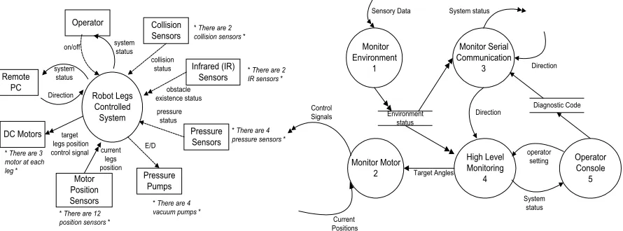
The environment model is used to build a clear model of the robot environment in this
specification analysis phase. The notations used in the environment model consist of:
•
Context diagram defines the external objects or external devices in the robot
system environment, shown in Fig. 2.
•
Event lists table aims to list all the possible objects and functions in the system for
further analysis and in the design stage.
•
Object timing estimation table, which the timing specification for each object in
the environment was estimated, shown in Table 2.
Robot Legs Controlled System Operator Collision Sensors Infrared (IR) Sensors Pressure Sensors Motor Position Sensors DC Motors Remote PC Pressure Pumps collision status obstacle existence status pressure status current legs position E/D target legs position control signal Direction system status
on/off systemstatus
* There are 3 motor at each leg *
* There are 4 vacuum pumps * * There are 12
position sensors *
* There are 4 pressure sensors *
* There are 2 IR sensors * * There are 2
collision sensors *
Monitor Environment 1 Monitor Motor 2 Monitor Serial Communication 3 Sensory Data High Level Monitoring 4 Direction Target Angles Control Signals Current Positions System status Operator Console 5 System status operator setting Environment status Direction Diagnostic Code
Object Min.-max. times
Collision Sensors – reading sensors 0.5 sec – 20 sec Infrared (IR) Sensors – reading sensors 2 sec – 30 sec Pressure Sensors – reading sensors 10 sec – 30 sec Pressure Pumps – activate or deactivate suction pads 20 sec – 1 min Motor Position Sensors – read sensors 5 millisec - 20 millisec DC Motors – increase or decrease joint angles 50 millisec – 100 millisec Remote PC – received or send data 1 sec – 10 sec
Operator – display system status 10-30sec
From the analysis of the environment model, the WCR control firmware can be divided
into five main functional operations: Monitor Environment,
Monitor Motor,
Monitor
Serial Communication,
High-level Monitoring and Operator Console. The behaviour of
the WCR transformation between the functions was presented using the Ward-Mellor
first level data flow diagram (DFD) shown in Fig. 3. For the WCR analysis,
data flowdiagram
(DFD) was used to make the analysis easier to understand. The software engineer
and the system engineer can easily produce and understand this diagram and the
correctness of this diagram is very important for the specification of the timing constraint
in the next stage. The first level of the system behavior is then detailed by the
Ward-Mellor’s second level decomposition of each module.
Fig. 2:WCR control system context diagram
.
Fig.3:First levels DFD for the WCR control system.
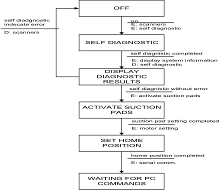
State transition diagram (STD) is used together with sequence diagram to model the
behaviour of the robot system such as the control flow in the robot system. Example of
the STD and the sequence diagram for event “Operator switch ON” with no error
condition from the diagnostic test are shown in Fig. 4 and Fig. 5 respectively.
OFF
SELF DIAGNOSTIC
on E: scanners E: self diagnostic
DISPLAY DIAGNOSTIC
RESULTS
self diagnistic completed E: display system information D: self diagnostic
ACTIVATE SUCTION PADS
self diagnistic without error E: activate suction pads self diadgnostic
indecate error D: scanners
home position completed E: serial comm.
SET HOME POSITION
suction pad setting completed E: motor setting
WAITING FOR PC COMMANDS
Operator
HLM Serial
Communication ControlMotors Operator switch on the robot system.
No error on the diagnostic test
Request START Self diagnostic request
wait for PC command
active control motor request, and move Homeposition
Diagnostic results activate all pads pressure assign Home home position
active serial comm. request ON robot
The WCR Control Firmware Design
Based on the robot software requirement analysis, at this stage the robot behaviour and
the robot constraints need to be presented in more detail, so that the design can be
translated directly to coding pattern. The robot firmware was designed according to three
design issues; tasks decomposition and task behavioural, task communication and
synchronization and timing performance.
From the WCR environment and behavioural model, it was clear that concurrent module
or processes presence in the operation of the robot. The five concurrent processes are
operator console, environment monitoring, PC communication, motor control and high
level control. From these concurrent modules, further tasks decomposition need to be
performed in order to divide the processes into smaller and manageable tasks and
Fig. 4:Operator switch “on” STD
.
functions, consequently transferred to tasks code to be scheduled by a real-time kernel.
Further task decomposition is performed, by detailing the WCR behavioural model using
statechart. The statecharts for the WCR control firmware environment monitoring module
are shown in Fig. 6.
Enable Monitor Environment
Reading Collusion Status Off enable monitor environment disable monitor environment Setting Env. Status [isDone] Reading Obstacle Status Waiting for Delay tm[Cdelay] Waiting for Delay tm[Odelay] [isDone] Waiting for Delay [isDone] tm[Envdelay] H H H
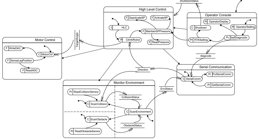
Task diagram is used to show the tasks synchronisation, shared data or interfaces between
tasks. From the task diagram Fig. 7, the design was divided based on the five main
function groups derived from requirement analysis stage. In each function module the
inner state are called substate. The basic state types for the climbing robot are cyclic (C),
function (F) and protected (Pr). All states with function and protected type will be called
by other state, the calling process is shown by arrow between the state. Only cyclic tasks
will not be called, this is because after the creation of the cyclic task, they will cycle
forever until the firmware is terminated.
Motor Control
Monitor Environment
Serial Communication High Level Control
Operator Console
C ScanCollision
C ScanObstacle
EnvStatus Pr ClimbRobot
C MotorCtrl F WriteDAC
F ReadADC F SenseLegPosition
TargetAngl
e
C ScanEnvironment F MaintainSPPressure
F ReadPressure F DeactivateSP F ActivateSP
C SerialComm
Pr GetSerialComm Pr PutSerialComm diagcode
Pr ReadCollisionSensor
Pr ReadObstacleSensor
Direction
Pr SelfDiagnostic Pr OperatorDisplay
Pr OperatorSetting
Pr RTKSetting
CollisionStatus
ObstacleStatus
C Shutdown shutdownstatus
C HLC
Fig. 6:Statechart for environment monitoring module
.
Each task is created in different module, dotted arrow shows the module create the task in
other module, for example module High Level Control created cyclic tasks called
MotorCtrl task, ScanEnvironment task and SerialComm task. Shared data between tasks
and modules are shown using data store box and the flow of the data transformation is
shown using double arrow. For example, TargetAngle data is generated by ClimbRobot
function and read by MotorCtrl task.
Seven concurrent tasks were identified from task diagram in Fig. 7. In order to schedule
the execution of the seven tasks using a preemptive real-time kernel, the priority of each
task needs to be assigned. The timing constraints information derived from the WCR
control firmware specification was used in the assigning tasks priority process. The
timing of the seven tasks was analysed using Rate Monotonic Scheduling (RMS)
technique to initialise priorities for each task. Basically, in RMS technique the tasks with
the highest rate of execution are given the highest priority. Based on this, the priority for
each task is assigned the priority.
CONCLUSION
A hybrid software engineering methodology was proposed for the WCR control firmware
development. The WCR firmware hybrid analysis and design flow are presented in detail
in this paper. Software engineering methods, models and techniques used in the WCR
control firmware specification analysis and design were also discussed. Based on the
WCR firmware design, the implementation stage is to gradually develop the firmware
part by part by building more and more functionality and non-functionality of the WCR
control firmware using software tools: Borland C/C++ 3.1 compiler, ROM locator for
generating ROMable code and µC/OS-II real-time kernel. A hardware-in-the-loop
simulation method is used for testing the implemented firmware. From the test results it
was found that by following the proposed hybrid method for developing the control
firmware, a firmware that conformed to the requirements set could be developed
successfully. The quality of the WCR control firmware reflects the effectiveness of the
hybrid software engineering methodology and the software tools used in the
methodology.
References
1. Ward, P. T. And Mellor, S. J. (1985). “Structured Development For Real-Time Systems”, Volume 1-3, New York: Yourdon Press.
2. Douglass B. P. (1998). Real-Time UML Developing Efficient Object For Embedded Systems, USA: Addison Wesley.
3. Burns A., Wellings A. J. (1995).HRT-HOOD: A Structured Design Method For Hard Real-Time System, Volume 3, Elsevier.
IMR71848 Intelligent Mobile Robot
Software
Document ID : URD-IMR71848
First Issue – august 2003Prepared: Dyg. Norhayati Abg.
Jawawi, FSKSM, UTM Date: 19 August 2003 Signature
Approved: Mohd Ridzuan Bin Ahmad Date: Signature
TABLE OF CONTENTS
1 INTRODUCTION ...3
1.1 PURPOSE...3 1.2 SCOPE...3
1.3 DEFINITIONS, ACRONYMS AND ABBREVIATIONS...4
1.4 REFERENCES...4
1.5 OVERVIEW...5
2 GENERAL DESCRIPTION ...6
2.1 PRODUCT PERSPECTIVE...6
2.2 GENERAL CAPABILITIES...6
2.3 GENERAL CONSTRAINTS...8
2.4 USER CHARACTERISTICS...9 2.5 OPERATIONAL ENVIRONMENT...9
2.6 ASSUMPTIONS AND DEPENDENCIES...11 3 SPECIFIC REQUIREMENTS ...12
3.1 CRUISE...13
3.2 COMMUNICATION WITH EXTERNAL PC...14 3.3 SENSOR MONITORING...15
3.4 HIGH-LEVEL CONTROL...16
3.5 CAPABILITY REQUIREMENTS...17
3.6 CONSTRAINTS REQUIREMENTS...18
3.6.1 Communication interfaces...18 3.6.2 Hardware Interfaces...18 3.6.3 Human-computer Interfaces (user interfaces)...18
User Requirements Definition Phase for Intelligent
Mobile Robot
Software
Abstract: This report describes a set of user requirements that apply to embedded software of a mobile Robot. This user requirement is prepared for the research Vot 71848 (Title - Experimental Evaluation of Hybrid Software Engineering Methodology for Embedded Firmware Development on Intelligence Mobile Robot) Research Group.
1 INTRODUCTION
1.1 Purpose
This document provides a definition of user requirements for the embedded software of an intelligent mobile robot. This software user requirement report is being prepared as part of a working group in UTM Vot 71848 Research Group (UTM71848RG).
Since these requirements are also connected to other user system requirements such as the robot hardware and mechanical system, some of the requirements may need to be adjusted, after review of the other work components. As such, it is an evolving document and is expected to undergo further review and refinement.
1.2 Scope
The software produced from this requirement will be called Intelligent Mobile Robot for 71848 research or called IMR71848 software. The IMR71848 software will be produce under the name of UTM71848RG. The software will be used to evaluate a hybrid software engineering methodology in intelligent mobile robot domain.
software requirement is mainly based on part of software robot requirement of a mobile robot, which is developed at UTM by [1] [2].
1.3 Definitions, Acronyms and Abbreviations
Priority - a mechanism used to order the request to run any task.
UTM – Universiti Teknologi Malaysia
UTM71848RG – UTM Vot 71848 Research Group LCD - Liquid Crystal Display
LED – Light Emitting Diod DC - Direct Current
IR - Infrared
I/O – Input and output
IMR - Intelligent Mobile Robot ADC – Analog to Digital Converter DAC – Digital to Analog Converter UR – User Requirement
TBC – To Be Confirmed
1.4 References
[1] Mohd Ridzuan Bin Ahmad, “Development of Reactive-Decentralized Control Algorithm for Intelligent Multi-Agent Robotics System in Cooperative Task Achievement”, Master of Engineering thesis, Faculty of Electrical Engineering, Universiti Teknologi Malaysia, August 2003.
[2] Dyg. Norhayati Abg. Jawawi, Ahmad Zariman Abd. Majid, Ahmad Ruzaimee Abd. Rashid, “Intelligent Mobile Robot Structure and Behaviour”, Technical Report VOT71848, Faculty of Computer Science and Information System, Universiti Teknologi Malaysia.
[4] Brooks R. A. (1986). “A Robust Layered Control System for a Mobile Robot”, IEEE Journal of Robotics and Automation, Vol. RA-2, No.1
[5] Thomas Braunl, (2003). “Embedded Robotics – Mobile Robot Design and Applications with Embedded Systems”, Springer
1.5 Overview
Kircanski defined mobile robot and intelligent mobile robot as followed [3]: “A mobile robot is an autonomous system capable of traversing a terrain with natural or artificial obstacles.”
“By the term intelligent in intelligent mobile robot means that the navigation is "task-oriented" and that it is based on dynamically sensing and modeling the external world.”
Based on the definition the UTM71848RG proposed a wheeled mobile robot capable of traversing in an environment, which is surrounded by four walls. The goal or task of the robot is to find a passage and exiting through the passage. Therefore, the goal of this Intelligent Mobile Robot (IMR) software is to control the movement the robot in finding a passage and exiting through the passage.
The IMR71848 software requirements have been partitioned into the following categories:
1) General description and background of the IMR software
2) Specific requirements include the software functional capability, performance and constraints. The specific software requirements in discussed in the following sub-title:
(a) Cruise
(b) Monitor Sensor (c) High-level navigation (d) Communication
2 GENERAL
DESCRIPTION
2.1 Product Perspective
The software product is a new software product for this particular UTM robot implementation i.e. the software product is not to replace an existing system. The software product is not standalone and it has to communicate with other part of software product such as intelligence robot software. The software also has to interact with other system components such as embedded controller, remote PC and the environment through sensors.
2.2 General Capabilities
The IMR71848 software must capable to control the movement the robot in finding a passage and exiting through the passage.During the cruising process, the IMR71848 software must support the intelligent components of the robot in order to ensure that the robot can response to the conditions in the environment in archiving the robot goal.
The mechanical construction of the robot is shown in Figure 1 and the side view of the robot is shown in Figure 2. The IMR consists of a body and two pair of wheels. The robot’s body is a three layers platform including a ground layer. The body carries the embedded controller and its associated electronics, and others load. The IMR71848 robot is a differential drive design robot. The cruising of the robot is supported a pair of drive wheels and a pair of castor wheels. Each drive wheels is move by a direct-current (DC) and the castor wheels are placed at the robot for stabilization of the IMR. The software is responsible to control the DC motors, in order control the movement of the IMR71848.
to move the robot and archive the robot’s goal, the software need to control the motor at each robot drive wheels, monitor the environments and navigate the robot. The embedded controller monitors its environment using four infrared (IR) proximity sensors, an infrared distance sensor and a digital camera. The embedded controller receives configuration commands and sends back information to a remote PC using wireless communication via Radio Frequency (RF) transceiver.
300 MM
155 MM
150 MM
Figure 1: The Mechanical Construction Of The IMR.
AMD188ES Embedded
Controller
East IR Proximity Sensor
West IR Proximity Sensor
South IR Proximity Sensor
North IR Proximity Sensor
D/A
Encoder
M Left Motor
Right Motor mo to r D riv e r D/A Encoder M mo to r D riv e r IR Distance Sensor RF Transceiver digital camera
Figure 3 : Block diagram of IMR controller.
2.3 General Constraints
The embedded software will control the functionality of the hardware (e.g. sensors and motors). The software development will not consider the detail specification of the hardware, only the specification that related to interfacing of the software and the hardware will be considered.
Another limitation that will be considered in the software development process is the hardware capability and size of the system such as memory and processor capabilities. These limitations will influence the selection of tools and methods used in the software development. It also limits the code size of the software produce.
To enables the use of good quality and low cost PC based C compilers such as from Borland and Microsoft in the software development, the developments process will be done in PC and the real external world input and output will be simulate.
budget of the software development limited to RM13000. This budget includes software development tools and robot hardware.
2.4 User Characteristics
The operator the system are technician and engineer, the involvement of the operator is listed in Table 1.
Technician Engineer Involvement phase Operation, testing, maintenance User requirements, operation,
testing, maintenance Education level Minimum SPM Minimum B.Sc. Experience with
such system 1-5 years 1-6 years Language Malay Malay, English
Table 1: Operator the system
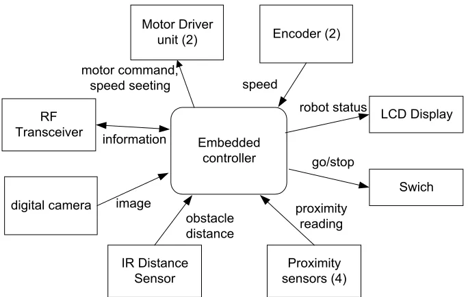
2.5 Operational Environment
The robot software is highly coupled to the external world. The relationship between the control software and the external devices is shown in Figure 2. Human operator starts or stops the robot through switch on/off button. Once the robot system is switched on the following operations with external devices need to be performed by the IMR71848 software:
1. Cruise. The robot movement needs to be controlled by sending commands to motor driver unit based on the environment monitoring.
2. Sensors monitoring. The environment must be monitored to detect the presence of obstacles using proximity sensors, distance sensor and digital camera.
3. High-level control. To navigate the robot intelligently toward the robot goal location and acknowledge the completion of the task.
4. Communication. The robot receives information from remote PC and sends robot information back to remote PC.
environment to find the passage. The robot needs to avoid obstacle exist within its environment.
Embedded controller Motor Driver
unit (2)
motor command, speed seeting
Encoder (2)
IR Distance Sensor RF
Transceiver
Proximity sensors (4) speed
proximity reading obstacle
distance information
digital camera image
LCD Display
Swich robot status
go/stop
Figure 2 : Graph showing external devices.
WALL
DOOR PASSAGE
200 CM 200 CM
70 CM
70 CM
2.6 Assumptions and Dependencies
It is assume for this requirements the requirements will be validated for the real controller system i.e. this requirement is applicable for software on embedded controller not only on PC. The end software product of the robot has to be tested at the embedded controller level. If the controller or hardware is not ready in the software-testing phase, a mechanism such as simulation of the hardware must be provided in this software development process. The requirements of the simulation software will not be consider in this requirement.
The success of meeting milestone date setup at each development phase for this software depend on the following events:
• Non-availability of RTOS when the development have to be started
• Non-availability of hardware or robot controller when the implementation and testing of the embedded software need to be started.
• Lack of skill of the development team to new experience and new tools – RTOS, Real-time methodologies selected, C programming for microcontroller systems and hardware programming
3 SPECIFIC
REQUIREMENTS
The IMR7848 is a wheeled robot that capable to move around its environment in archiving the robot following goals:
• Finding a passage
• Exiting through the passage
• Avoid obstacles
• Maintain the robot at certain speed
The IMR7848 software is to move the wheels of the robot until the robot archive the robot’s goals (UR1). In order to move the robot and archive the robot’s goal, the software need to control the DC motors at each robot drive wheels, monitor the environments and navigate the robot.
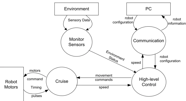
The program starts to operate when the user switches on the robot and end when the user switches off the robot (UR2). Once the robot system is switched, the main operation of the robot software is divided into four main groups (UR3) as follows:
i. Cruise. This software component enables the IMR to move around its environment. This module needs to send command to motor driver based on the movement commands received from high-level navigation module.
ii. Monitor sensors. Based from the reading from the sensors, this component software presented the environment status for high-level navigation module. iii. High-level Control. In archiving the robot’s goal, this module supports the
intelligent component of the robot. Based on the environment status received from monitor sensors module, this module will decide the behaviour of the robot. Based on this behaviour the movement of the robot will be identified. iv. Communication. The robot configuration send to the robot through wireless
communication, based on this configuration the robot will be configure before the robot journey started. The robot movement and sensor data will be monitored using the remote PC.
Environment
Monitor Sensors
Cruise High-level Control Robot
Motors
Sensory Data
Environm ent Status
motors
command
Timing
pulses
movement commands
speed
PC
Communication
robot
configuration informationrobot
speed
robot configuration
Figure 4: Interaction between the robot functional operation.
3.1 Cruise
Cruise software component control the IMR71848 movement around the robot environment (UR4). Based on movement commands that are received from High-level control module, the IMR71848 motor will be control in order to control the IMR71848 movement (UR5). Movement commands elements are (UR6):
1. Status: stop or go
2. Direction: straight or turning
The direction movement of the robot can be classified into two (UR7):
• Straight – two types of direction forward or backward.
• Turning – either left or right and each turning is 45 degree.
This cruise module received tuning pulses from encoder in the robot motor. This module is responsible to change the tuning pulses reading to speed value of the motor (UR8).
Based on the received movement command from high-level navigation module and the current speed of the motor, at each sampling period the control signals to the DC motors are calculated using the proportional-integral (PI) control algorithm (UR9):
Where,
u(t) is the control signal at time t
e(t) is the error between the target speed and the current speed at time t Kp and Ki are constants for each motor.
The computation of the control signal must be completed within 100 milliseconds to ensure the constant speed of the robot (UR10).
3.2 Communication with External PC
To monitor the movement of the IMR17848 robot, it is communicated to a remote PC. The IMR17848 communicates with a remote PC to receive configuration commands and sending back information via a Radio Frequency (RF) transceiver (UR11). Configuration commands are the setting up of the robot before the robot starts it movement (UR12). Information that sends to the remote PC is the robot speed and direction (UR13).
In IMR17848 software design, the designer doesn’t really care what software on the remote PC does. The designer just concern with the controller on the robot and how it interface. The remote PC software will be specified in other document.
3.3 Sensor monitoring
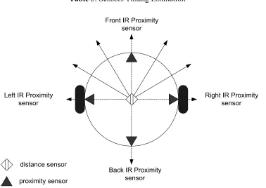
The embedded controller monitors its environment using some sensors. The sensors provide information for the IMR7848 software to enable the software to eliminate interferences due to the collision with obstacles and walls (UR14). Besides, the sensors help the robot to plan its movement (UR15). The robot environment is monitored using:
1. Four IR proximity sensors to detect the presence of obstacles during the forward and reverse movement of the robot (UR16).
2. An IR distance sensor to estimate the distance of obstacles and walls from the robot current location (UR17).
3. A digital camera to detect shape of objects in the robot’s environment (UR18).
The implementation of IMR7848 software is divided into three main incremental phases based on the sensors and communication introduced to the robot. The phases suggested are as shown in Table 2.
Phase Sensor added Robot Capability
Basic IR proximity Find wall and follow the walls to detect passage.
Medium IR distance, RF
transceiver Differentiate wall and other static obstacle. Advanced Digital camera TBC
Table 2: The IMR71848 incremental phases.
The requirement specified in this document will cover basic and medium phase in detail, the implementation of the advanced phase will be specified in detail later (TBC04).
The IMR7848 software needs to periodically get information from the environment through sensors, and the maximum period or cycle for reading the each sensor is listed in Table 3 (UR21). The reading of the sensors is called environment status.
Object Min.-max. times
IR Proximity Sensors – reading sensors 0.5 sec – 1 sec IR Distance Sensor – reading sensors 1 sec – 2 sec
Table 3: Sensors Timing Estimation
Front IR Proximity sensor
Back IR Proximity sensor
Right IR Proximity sensor Left IR Proximity
sensor
proximity sensor distance sensor
Figure 5: Sensors position and directions.
3.4 High-level Control
The robot can be moved forward, reverse, turn left and turn right. The robot moves at constant speed level during straight movement and this speed will be change during turning movement (UR22). The speed levels of the robot are depending on the distance of the robot from an obstacle (TBC05). The robot speed will be display on Liquid Crystal Display (LCD) display. Besides the robot’s speed, the battery status will also be displayed on LCD (UR23).
conditions in the environment in archiving the robot goal (UR24). The intelligence of the IMR71848 robot is supported by subsumption architecture proposed by Professor Rodney Brooks from Mobile robot Group, MIT Artificial Intelligent Laboratory [4]. The implementation of this architecture toward IMR71848 is based on Mohd Ridzuan 2003 (UR25). Based on Mohd Ridzuan, IMR71848 robot basic behaviour are as followed (UR26):
1. Cruise – The ability of the robot to move around its environment. 2. Wall Detection – The ability of the robot to detect and follow the wall.
3. Obstacle avoidance – The ability of the robot to avoid collision with any obstacle.
4. Passage detection – The ability of the robot to reach the wall passage.
5. Task Completion – The ability of the robot to acknowledge the completion of the robot task once the robot manage to exit the passage.
In subsumption architecture all the above behaviours run in parallel, the higher-level behaviours have the power to suppress the lower-level behaviour. Each behaviour is assigned priority level as shown in Table 4 (UR27). The highest priority is given the lowest number.
Behaviour Priority Cruise 5 Wall Detection 4
Obstacle avoidance 3 Passage detection 2 Task Completion 1
Table 4: Behaviour priority level.
The navigation algorithm used by IMR71848 is wandering standpoint algorithm [4]. The algorithm try to reach from start in direct line, and when encounter an obstacle the robot will follow around the object until the goal direction is clear again (UR28).
3.5 Capability Requirements
The hardware capability is 128K EPROM and 128 RAM. The size and the memory usage of the IMR7848 software must be with this capability.
The type and the timing specification of the information transfer to remote PC depending on the capability of the RF transceiver.
3.6 Constraints Requirements
3.6.1 Communication interfaces
The format of the data packet received and sends back to the external PC is yet to be defined (TBC06).
3.6.2 Hardware Interfaces
The software has to run on embedded processor (UR29). The main hardware requirements of the system are as follows (UR30):
• Controller - based on Intel AMD188ES microcontroller
• EPROM - 128 K
• RAM - 128 K
• Parallel I/O
• Serial I/O
• ADC/DAC
• Switches on/stop
• LCD Display
3.6.3 Human-computer Interfaces (user interfaces)
At this stage it is assume all input and output to the system done through remote PC and LCD display, LED display and switches (UR31).
Local user interfaces detail are as followed (UR32):
• 2 switches to start and stop robot
• a LCD to display robot status and diagnostic results
Appendix A: List of User Requirements
UR No. User Requirements Description
1. The IMR7848 software is to move the wheels of the robot until the robot archive the robot’s goals.
2. The program starts to operate when the user switches on the robot and end when the user switches off the robot
3. Once the robot system is switched, the main operation of the robot software is divided into four main groups
4. Cruise software component control the IMR71848 movement around the robot environment
5. Based on movement commands that are received from High-level control module, the IMR71848 motor will be control in order to control the IMR71848 movement
6. Movement commands elements are status and direction.
7. The direction movement of the robot can be classified into two: straight and turning. 8. This cruise module is responsible to change the tuning pulses reading to speed value
of the motor.
9. Based on the received movement command from high-level navigation module and the current speed of the motor, at each sampling period the control signals to the DC motors are calculated using the proportional-integral (PI) control algorithm.
10. The computation of the control signal must be completed within 100 milliseconds to ensure the constant speed of the robot.
11. To monitor the movement of the IMR17848 robot, it is communicated to a remote PC. The IMR17848 communicates with a remote PC to receive configuration commands and sending back information via a Radio Frequency (RF) transceiver.
12. Configuration commands are the setting up of the robot before the robot starts it movement.
13. Information that sends to the remote PC is the robot speed and direction.
14. The sensors provide information for the IMR7848 software to enable the software to eliminate interferences due to the collision with obstacles and walls.
15. The sensors help the robot to plan its movement.
16. Four IR proximity sensors to detect the presence of obstacles during the forward and reverse movement of the robot.
17. An IR distance sensor to estimate the distance of obstacles and walls from the robot current location.
18. A digital camera to detect shape of objects in the robot’s environment.
19. Four IR proximity sensors use to detect the existence of obstacle at four direction of the robot: front, back, left and right.
20. An IR distance sensor will rotate 180 degree with 15 degree for each distance reading; therefore, with 180 degree rotation can record 7 different directions of distance reading.
21. The IMR7848 software needs to periodically get information from the environment through sensors, and the maximum period or cycle for reading the each sensor is listed in Table 3.
22. The robot moves at constant speed level during straight movement and this speed will be change during turning movement.
23. The robot speed will be display on Liquid Crystal Display (LCD) display. Besides the robot’s speed, the battery status will also be displayed on LCD.
25. The implementation of subsumption architecture toward IMR71848 is based on Mohd Ridzuan 2003
26. IMR71848 robot basic behaviour are cruise, wall detection, obstacle avoidance, passage detection and task completion.
27. Each behaviour is assigned priority level as shown in Table 4.
28. The navigation algorithm used by IMR71848 is wandering standpoint algorithm. The algorithm try to reach from start in direct line, and when encounter an obstacle the robot will follow around the object until the goal direction is clear again
29. The software has to run on embedded processor
30. The main hardware requirement of the system : Intel AMD188ES microcontroller, 128K EPROM and 128 RAM, Parallel I/O, ADC/DAC, Switches on/stop and LCD Display.
31. At this stage it is assume all input or output to the system done through remote PC and LCD display.
32. Local user interfaceS detail are 2 switches to start and stop robot, a LCD to display robot status and diagnostic results and LED display diagnostic results.
Appendix B: List of User Requirements to be confirmed
UR No. User Requirements Description
1. IMR7848 software needs to maintain the robot at constant speed level
2. To make a right turn the speed of the left motor (TBC02) is faster than the right motor (TBC02).
3. To make a left turn the speed of the right motor (TBC03) is faster than the left motor (TBC03).
4. The requirement specified in this document will cover basic and medium phase in detail, the implementation of the advanced phase will be specified in detail later.
5. The speed levels of the robot are depending on the distance of the robot from an obstacle.
IMR71848 Intelligent Mobile Robot
Software
Document ID: SRS- IMR71848
First Issue - December 2003
Prepared: Dyg. Norhayati Abg.
Jawawi, FSKSM, UTM Date:2003 30 December Signature
TABLE OF CONTENTS
1 INTRODUCTION ... 3
1.1 PURPOSE... 3 1.2 SCOPE... 3
1.3 DEFINITIONS, ACRONYMS AND ABBREVIATIONS... 4
1.4 REFERENCES... 4
1.5 OVERVIEW... 5
2 GENERAL DESCRIPTION ... 6
2.1 RELATIONS TO CURRENT PROJECTS... 6
2.2 RELATION TO PREDECESSOR AND SUCCESSOR PROJECTS... 6
2.3 FUNCTION AND PURPOSE... 6
2.4 ENVIRONMENTAL CONSIDERATIONS... 6
2.4.1 Robot Hardware Environments... 6 2.4.2 Robot Operating Environments... 7 2.4.3 Operating Environments in the Development Systems... 7
2.5 RELATION TO OTHER SYSTEMS... 8 2.6 GENERAL CONSTRAINTS... 9 2.7 MODEL DESCRIPTION... 9
3 SPECIFIC REQUIREMENTS ... 11
3.1 ENVIRONMENT MODEL... 11
3.2 BEHAVIOURAL MODEL... 13
Software Requirements Specification for IMR71848 Intelligent Mobile
Robot Software
Abstract: This report describes a set of software requirements that apply to an intelligent mobile robot system. This report is prepared for the research Vot 71848 (Title - Experimental Evaluation of Hybrid Software Engineering Methodology for Embedded Firmware Development on Intelligence Mobile Robot) Research Group. This document is an evolving document and is expected to undergo further review and refinement.
1 INTRODUCTION
1.1 Purpose
This specification document provides a definition of software requirements for the embedded software of an intelligent mobile robot. It is based on requirements analysis of the user requirements (URS-IMR71848). This report will be used as the main reference for the detail design of the Intelligent Mobile Robot under Vot 71848 (IMR71848) software. Therefore the readers of this document are IMR71848l software designer, IMR71848 requirement analyser for next incremental stage or maintenance purposes and the IMR71848 verification team.
This software requirement report is being prepared as part of a working group in UTM VOT 71848 research member group (UTM71848RG).
1.2 Scope
1.3 Definitions, Acronyms and Abbreviations
ADC – Analog to Digital Converter DAC – Digital to Analog Converter DC - Direct Current
I/O – Input and output IR - infrared
LCD - Liquid Crystal Display LED – Light Emitting Diode PI - Proportional-Integral
RF - Radio Frequency transceiver RTK – Real-time Kernel
RTOS – Real-time Operating Systems SPM – Sijil Peperiksaan Malaysia USR – User Requirement Specification UTM – Universiti Teknologi Malaysia UTM – Universiti Teknologi Malaysia
UTM71848RG – UTM Vot 71848 Research Group WCR - Wall climbing Robot
1.4 References
[1] Mohd Ridzuan Bin Ahmad, “Development of Reactive-Decentralized Control Algorithm for Intelligent Multi-Agent Robotics System in Cooperative Task Achievement”, Master of Engineering thesis, Faculty of Electrical Engineering, Universiti TeknologiMalaysia, August 2003.
[2] Dayang. Norhayati Abang. Jawawi, Ahmad Zariman Abd. Majid, Ahmad Ruzaimee Abd. Rashid, “Intelligent Mobile Robot Structure and Behaviour”, Technical Report VOT71848, Faculty of Computer Science and Information System, Universiti Teknologi Malaysia.
[4] Brooks R. A. (1986). “A Robust Layered Control System for a Mobile Robot”, IEEE Journal of Robotics and Automation, Vol. RA-2, No.1
[5] Thomas Braunl, (2003). “Embedded Robotics – Mobile Robot Design and Applications with Embedded Systems”, Springer
[6] Dayang. Norhayati Abang. Jawawi, “User Requirements Definition Phase for IMR71848 Intelligent Mobile Robot Software”, Faculty of Computer Science and Information System, UTM, August 2003
1.5 Overview
The requirements have been partitioned into the following categories: 1. General description of the IMR71848 firmware project
2. IMR71848 formware specific requirement 2.1.1. Environment Model
2.1.2. Behavioural Model
2 GENERAL
DESCRIPTION
2.1 Relations to Current Projects
This robot software project is being prepared as part of a working group in UTM71848RG. The parent project is funded under UTM grant, vot number 71848. The objective of the patent project is to evaluate experimentally a hybrid software engineering methodology for embedded firmware development on intelligent mobile robot. This software project develops a firmware of the UTM IMR71848 and used for the software methodology evaluation purposes. Previous work on developing firmware for UTM Wall Climbing Robot, has tested the software methodology under hardware-in-the-loop simulation and was found to be effective.
2.2 Relation to Predecessor and Successor Projects
This software prototype is mainly based on software methodology implemented on (Dayang, 2002) and the software intelligence of the robot is based on (Ridzuan, 2003).
2.3 Function and Purpose
The main function of the embedded digital controller is to move the wheels of the robot until the robot archive the goal. In order to move the robot and archive the robot’s goal, the software need to control the motor at each robot drive wheels, monitor the environments and navigate the robot.
2.4 Environmental Considerations
2.4.1 Robot Hardware Environments
I/O, Serial I/O, ADC/DAC, Switches on/stop and Status LED. The embedded controller monitors its environment using some sensors - four infrared proximity sensors, an infrared distance sensor and a digital camera. It also communicates with a remote PC via a Radio Frequency (RF) transceiver.
2.4.2 Robot Operating Environments
The experiment environment of the mobile robot is indoor environment. The robot’s environment is surrounded with walls except for the doorway passage. Figure 1 shows the experiment environment of the IMR71848. The IMR71848 cruise around the environment to find the passage. The robot needs to avoid obstacle exist within its environment.
WALL
DOOR PASSAGE
200 CM 200 CM
70 CM
70 CM
Figure 1: Experiment environment of IMR71848.
2.4.3 Operating Environments in the Development Systems
• The software development environment – Windows95 and DOS environments
• Software development tools – Borland C compiler version 3.1, Assembler • MicroC/OS-II real-time operating system used for intertasks communication
• ROM locator for generating ROMable code
2.5 Relation to other Systems
The firmware is a subsystem of a complete IMR71848 system. Figure 2 shows the major component of the IMR71848 system and the interconnection of the IMR71848 firmware in the system.
AMD188ES Embedded
Controller
East IR Proximity Sensor
West IR Proximity Sensor
South IR Proximity Sensor
North IR Proximity Sensor
D/A
Encoder
M Left Motor
Right Motor mo to r D riv e r D/A Encoder M mo to r D riv e r IR Distance Sensor RF Transceiver digital camera
Figure 2: Block diagram of IMR controller.
Figure 1 shows that the robot controller system involves the following entities.
1. An operator – The operator has the ability to start and stop the robot. The operator is also provided with a display given information of the robot status and the robot movements.
2. IR proximity sensors – The sensors detect the presence of obstacles during the movement of the robot.
3. IR distance sensor – The sensor estimate the distance of obstacles and walls from the robot current location
4. Digital camera – The camera detect shape of objects in the robot’s environment 5. Radio Frequency (RF) transceiver – To communicate to a remote PC.
7. Encoders – A feedback mechanism of the robot motor. The software will receive tuning pulses from encoder in the robot motor.
2.6 General Constraints
General constraints of the firmware development are: 1. Budget
2. Hardware
3. The used of the available tools and facilities in UTM only
2.7 Model Description
A hybrid methodology is proposed for the IMR71848 firmware analysis model. In the proposed hybrid methodology, several suitable notations and diagrams taken from Ward-Mellor Structured Development for Real-Time Systems (Ward-Mellor), Unified Modeling Language for Real-Time (UML-RT) and Hard Real-Time Hierarchical Object Oriented Design (HRT-HOOD) methodologies were used to specify and design the robot control firmware. The models and techniques used in the hybrid analysis are summarised in Table 1. In the specification stage the notations and diagrams from Ward-Mellor and HRT-HOOD were used. In the design stage notations and diagrams from UML-RT and HRT-HOOD were used.
Based on the captured requirement (Dayang, 2003), the analysis of the IMR71848 firmware will be modeled using environment model and behavioural model. The environment model is used to build a clear model of the robot environment in this specification analysis phase. The notations used in the environment model consist of:
• Context diagram defines the external objects or external devices in the robot system environment.
• Event lists table aims to list all the possible objects and functions in the system for further analysis and in the design stage.
Table 1 : The models and techniques used in hybrid methodology.
No. Modeling stage Techniques and tools used Methodology used 1. Environment model Outside-in structuring Ward-Mellor
Tools
Context diagram Event list table
Timing estimation table
Ward-Mellor Ward-Mellor HRT-HOOD 2. Behavioural model
2.1. First level decomposition Structured-object model HRT-HOOD
Tools
Use-case diagram Data flow diagram Functional group table Package diagram
Ward-Mellor HRT-HOOD
2.2. Detail functions
decomposition Tools Data flow diagram Sequence diagram
Ward-Mellor UML-RT 2.3. Non-functional
decomposition
Tools
Event-response table Statechart diagram Sequence diagram
Ward-Mellor UML-RT UML-RT
3 SPECIFIC
REQUIREMENTS
This section contains statements and discussions of requirements applicable to IMR71848 software. The discussion contains a statement of top-level requirements, refinements of requirements where there was agreement by the members of the working group, and an identification of issues that require further considerations.
3.1 Environment Model
The IMR71848 firmware environment model is defined using context diagram, (is shown in Figure 3), event list table (is shown in Table 2) and object timing estimation table (is shown in Table 3).
Robot Control System
Switch IR Distance
Sensor IR Proximity Sensors LCD Display Encoder Motors RF Transceiver distances reading obstacle existence status
robot sta tus sp ee d spee d set ting robot configuration robot information
* There are 2 motors *
* There are 2 encoders *
* There are 4 sensors * motor command go/s top Camera image
Figure 3: IMR71848 context diagram