Scholarship at UWindsor
Scholarship at UWindsor
Electronic Theses and Dissertations Theses, Dissertations, and Major Papers
Winter 2014
Efficient finite field computations for elliptic curve cryptography
Efficient finite field computations for elliptic curve cryptography
Wangchen Dai University of Windsor
Follow this and additional works at: https://scholar.uwindsor.ca/etd
Part of the Electrical and Computer Engineering Commons
Recommended Citation Recommended Citation
Dai, Wangchen, "Efficient finite field computations for elliptic curve cryptography" (2014). Electronic Theses and Dissertations. 5017.
https://scholar.uwindsor.ca/etd/5017
This online database contains the full-text of PhD dissertations and Masters’ theses of University of Windsor students from 1954 forward. These documents are made available for personal study and research purposes only, in accordance with the Canadian Copyright Act and the Creative Commons license—CC BY-NC-ND (Attribution, Non-Commercial, No Derivative Works). Under this license, works must always be attributed to the copyright holder (original author), cannot be used for any commercial purposes, and may not be altered. Any other use would require the permission of the copyright holder. Students may inquire about withdrawing their dissertation and/or thesis from this database. For additional inquiries, please contact the repository administrator via email
by
WANGCHEN DAI
A Thesis
Submitted to the Faculty of Graduate Studies
through Electrical and Computer Engineering
in Partial Fulfillment of the Requirements for
the Degree of Master of Applied Science
at the University of Windsor
Windsor, Ontario, Canada
2013
by
WANGCHEN DAI
APPROVED BY:
Dr. D. Wu
School of Computer Science
Dr. C. Chen
Department of Electrical and Computer Engineering
Dr. H. Wu, Advisor
Department of Electrical and Computer Engineering
I hereby certify that I am the sole author of this thesis and that no part of this thesis has
been published or submitted for publication.
I certify that, to the best of my knowledge, my thesis does not infringe upon anyones
copyright nor violate any proprietary rights and that any ideas, techniques, quotations, or
any other material from the work of other people included in my thesis, published or
oth-erwise, are fully acknowledged in accordance with the standard referencing practices. Fur-thermore, to the extent that I have included copyrighted material that surpasses the bounds
of fair dealing within the meaning of the Canada Copyright Act, I certify that I have
ob-tained a written permission from the copyright owner(s) to include such material(s) in my
thesis and have included copies of such copyright clearances to my appendix.
I declare that this is a true copy of my thesis, including any final revisions, as approved
by my thesis committee and the Graduate Studies office, and that this thesis has not been
submitted for a higher degree to any other University or Institution.
Finite field multiplication and inversion are two basic operations involved in Elliptic Cure
Cryptosystem (ECC), high performance of field operations can be applied to provide
effi-cient computation of ECC. In this thesis, two classes of fields are proposed for multipliers
with much reduced time delay. A most-significant-digit first and a least-significant-digit
first digit-serial Montgomery multiplications are also proposed, using novel fixed elements
R(x) which are different from xm and xm−1. Architectures of the proposed Montgomery multipliers are studied and obtained for the fields generated by the irreducible
pentanomi-als, which are selected based on the proposed special finite fields. Complexities of the
Montgomery multipliers in term of critical path delay and gate count of the architectures
are investigated; the critical path delay of the proposed multipliers are found to be as good
as or better than the existing works for the same class of fields. Then, implementation of the
proposed multipliers (m=233) using Field Programmable Gate Array (FPGA) is provided. In addition, an FPGA implementation of an efficient normal basis inversion algorithm is
also presented (m=163). The normal basis multiplication unit is implemented using a digit-level structure, and a C-code is written to generate the first coordinate of the product of two normal basis elements for all field sizem.
Key Words: Montgomery multiplication, digit-serial, Elliptic Curve Cryptography,
normal basis inverse, FPGA.
I dedicate this thesis to my parents for supporting me to accomplish my master’s degree at
University of Windsor in Canada.
I would like to express my sincere gratitude and appreciation to everyone who helped make
this thesis possible. I am deeply indebted to my supervisor Prof. Huapeng Wu, Professor of
Electrical and Computer Engineering at University of Windsor, for guiding me throughout
the writing of this thesis. As one of best teachers I have ever had, Professor Wu impressed
upon me that a good teacher instructs students in matters far beyond those in textbooks. His
broad knowledge and logical way of thinking have been of great value; without his detailed and constructive comments on my research, none of this thesis would be possible.
I would also grateful to my colleagues and friends, Yiruo He, Ya Tan, Ran Xiao and
Shoaleh Hashemi Namin for their time and support.
Finally, I with to extend my gratitude to everyone at UWindsor’s Faculty of ECE for
their efforts during my study in the M.A.Sc. Program. I also gratefully acknowledge the
financial support form University of Windsor and Professor Huapeng Wu.
Author’s Declaration of Originality iii
Abstract iv
Dedication v
Acknowledgments vi
List of Figures x
List of Tables xii
List of Appendices xiv
List of Abbreviations/Symbols xv
1 Introduction 1
2 Mathematical Preliminaries 4
2.1 Finite Field and Representations . . . 4
2.2 Montgomery Multiplication overGF(2m) . . . 6
2.3 Elliptic Curve Cryptosystem . . . 7
2.3.1 Elliptic Curves . . . 7
2.3.2 Finite Field Inversion Using Normal Basis . . . 9
2.3.3 Elliptic Curve Cryptosystem . . . 10
3 A Review of Existing Work 13
4 Proposed Digit-serial Montgomery Multipliers 19
4.1 Proposed Digit-Serial MSD First Montgomery Multiplier . . . 19
4.1.1 Algorithm . . . 20
4.1.2 General Architecture . . . 21
4.1.3 Advanced Architecture . . . 26
4.2 Proposed Digit-Serial LSD First Montgomery Multiplier . . . 31
4.2.1 Algorithm . . . 31
4.2.2 General Architecture . . . 32
4.2.3 LFSR-Based Architecture . . . 36
4.3 Complexity Analysis . . . 38
4.4 FPGA Implementation of the Proposed Multipliers . . . 42
4.4.1 Summary of the MSD-First Multiplier Implementation . . . 42
4.4.2 Summary of the LSD-First Multiplier Implementation . . . 43
5 FPGA Implementation of Inverse Generator 45 5.1 The Design of Inverse Generator . . . 45
5.1.1 REG1 Module . . . 46
5.1.2 REG2 Module . . . 47
5.1.3 MUX Module . . . 48
5.1.4 Digit-level Normal Basis Multiplier Module and Multiplication Al-gorithm . . . 48
5.1.5 Top-Level . . . 52
5.2 Simulation and Compilation . . . 52
5.2.1 Simulation Results . . . 52
5.2.2 Compilation Results . . . 54
6 Conclusions 59
A C-code ofF(s)and the First Coordinatec0Generation 61
B Generated VerilogHDL-code of the First Coordinatec0 66
2.1 Operations in an elliptic curve . . . 7
2.2 Elliptic curve over binary fieldGF(2m) . . . 9
2.3 Encryption/decryption of elliptic curve cryptosystem . . . 10
2.4 Computation structure of ECC overGF(2m) . . . 11
3.1 (a)Tang’s architecture ofGF(2233)multiplier [17] (b)Kumar’s architecture ofGF(2m)multiplier [19] . . . 15
3.2 Tang’s architecture of partial product multiplier, generates the product of Aj×B[17] . . . 16
3.3 Meher’s block diagram of proposed field multiplier overGF(2m)[24] . . . 17
3.4 Work reported in [28], (a)R(x) =xm, (b)R(x) =xm−1 . . . 18
4.1 Block diagram of proposed digit-serial MSD-first Montgomery multiplier whenR(x) =xl . . . 22
4.2 General architecture of the proposed multiplier whenR(x) =xu . . . 23
4.3 Implementation of equation (4.11) . . . 25
4.4 Model 1: multiply byxstructure . . . 27
4.5 Implementation of computationA(x)x2 mod f(x) . . . 28
4.6 Model 2: multiply byx−1structure . . . 29
4.7 Implementation ofA(x)Bs−i−1(x)x−l mod f(x) . . . 30
4.8 Advanced architecture of proposed multiplier . . . 30
4.9 General architecture of the proposed digit-serial LSD first multiplier . . . . 33
4.10 LFSR-based architecture of the proposed LSD Montgomery multiplier . . . 37
5.1 Architecture of the designed inverse generator . . . 46
5.2 Block diagram of the inverse generator for FPGA implementation . . . 47
5.3 REG1 module . . . 48
5.4 REG2 module . . . 48
5.5 MUX module . . . 49
5.6 Digit-level normal basis multiplier module . . . 49
5.7 Digit-level Normal Basis multiplier structure . . . 50
5.8 Simulation result of the Inverse Generator . . . 56
5.9 RTL of the design . . . 57
1.1 Key size comparison between RSA and ECC with same secure level . . . . 2
2.1 Algorithm of Binary Field Bit-Parallel Montgomery Multiplication . . . 6
3.1 Algorithm of Bit-Serial Montgomery Multiplication . . . 14
3.2 Algorithm of Digit-Serial Montgomery Multiplication, wheredis the digit size, f00(x)f0(x) =1 modxd,C0(x)and f0(x)are the least significant digits ofC(x)and f(x), respectively . . . 14
4.1 Digit-serial MSD-first Montgomery Multiplier (R(x) =xl), where 06l6 d−1 . . . 21 4.2 Complexity of each block of the proposed MSD-first Montgomery multiplier 26
4.3 Complexity of proposed digit-serial MSD-first Montgomery multiplication
(Algorithm I, general architecture, when ki+1−ki>d−1,k0=0,k4=m
and 06l6d−1) . . . 26 4.4 Complexity of proposed digit-serial MSD-first Montgomery
multiplica-tion (Algorithm I, advanced architecture, whenki+1−ki>max{l,d−l− 1}, i=0,1,2,3, k0=0, k4=mand 06l6d−1) . . . 31
4.5 Digit-serial LSD-first Montgomery Multiplier (R(x) =xsl), wherel>0 . . 32 4.6 . . . 33
4.7 Complexity of digit-serial LSD Montgomery multiplication (Algorithm II,
when 16l6d−1 andki+1−ki>d−1, k0=0, k4=m) . . . 34 4.8 Complexity of digit-level Montgomery multiplication (Algorithm II, when
l=d, andki+1−ki>d−1, k0=0, k4=m) . . . 34 4.9 Degree range of each term of equation (4.22) . . . 35
4.10 Value oflin terms of XOR gate usage of block S1 . . . 35
4.11 Complexity of digit-level Montgomery multiplication (Algorithm II, when
l>d, andki+1−ki>l, k0=0, k4=m) . . . 36
4.12 LFSR-Based Digit-serial LSD-first Montgomery Multiplier (R(x) =xsl), where 06l6d−1 . . . 36
4.13 Complexity of digit-level Montgomery multiplication (Algorithm III, when 06l6d−1, andki+1−ki>max{l,d−l−1}, k0=0, k4=m) . . . 38
4.14 Intrinsic delay of XOR2 and AND2 gate, we assume each gate could drive a maximum of two gates (25°C, 1.8V, CMOSP18 Tech.,Y=A·B, orY=A⊕B) 38 4.15 Digit-serial Montgomery multipliers comparison (f(x) =xm+xk3+xk2+ xk1+1,s=m/d) . . . 39
4.16 Proposed multipliers compared with Polynomial Basis finite field multipli-ers (MSD cases, f(x) =xm+xk3+xk2+xk1+1,s=dm/de,T DFF represents the time delay of a D-flipflop) . . . 39
4.17 Proposed multipliers compared with Polynomial Basis finite field multipli-ers (LSD cases,TM represents the time delay of a 2×1 Multiplexer,TT FF represents the time delay of a T-flipflop) . . . 40
4.18 Efficiency of the proposed multipliers and existing Montgomery multipli-ers (m=233,d=8, ifl<d, thenl=4) . . . 41
4.19 Efficiency of the proposed multipliers and existing PB multipliers (m= 233,d=8, ifl<d, thenl=4) . . . 41
4.20 Cells usage of compilation (m=233,d=8,u=4) . . . 42
4.21 Gate count of each module (m=233,d=8,u=4) . . . 42
4.22 Time complexity of the design (m=233,d=8,u=4) . . . 43
4.23 Cells usage of compilation (m=233,d=8,l=4) . . . 43
4.24 Gate count of each module (m=233,d=8,l=4) . . . 43
4.25 Time complexity of the design (m=233,d=8,l=4) . . . 44
5.1 Description of Each Clock cycle . . . 52
5.2 Cells usage of compilation . . . 55
5.3 Area cost of each module . . . 55
C-code ofF(s)and the First Coordinatec0Generation . . . 61
Generated VerilogHDL-code of the First Coordinatec0 . . . 66
GF Finite Field or Galois Field
PB Polynomial Basis
NB Normal Basis
EC Elliptic Curve
ECC Elliptic Curve Cryptosystems
RSA Rivest, Shamir, Adleman
FPGA Field Programmable Gate Array
ALUT Adaptive Look Up Tables
MSD Most Significant Digit
LSD Least Significant Digit
LE Logic Element
MUX Multiplexer
XOR Exclusive OR
TFF T-Flipflop
DFF D-Flipflop
LFSR Linear Feedback Shift Register
VLSI Very Large Scale Integrated Circuits
Introduction
The development of cryptography can be divided into the following two stages [1]:
classi-cal cryptography, and modern cryptography. Classiclassi-cal cryptography was the study of the confidentiality of a message through encryption and decryption. An encryption operation
can be described as the conversion of a message or a piece of information from
compre-hensible text into some incomprecompre-hensible form. Transposition cipher [3] and substitution
cipher [2] are two representative classical ciphers.
Due to the rapid development of computer and network technologies, and the
world-wide application of on-line trading services, mobile phones, and credit cards, the increasing
threat to personal privacy and information security is becoming a significant challenge to
security engineers. Under this context, cryptography is no longer just a concern for
gov-ernments, but for civilians as well. Therefore, this field has been expanded far beyond communication confidentiality to include identity authentication, digital signatures,
mes-sage integrity verification, etc. This extension has led to modern cryptography. Cipher
algorithms in modern cryptography are achieved by using a key to encrypt and decrypt
information. The Data Encryption Standard (DES) and the Advanced Encryption Standard
(AES) are two symmetrical cipher algorithms created in modern cryptography. The
en-cryption and deen-cryption of these algorithms share the same key. The problem is that over
time, more users know the key, and the risk of security breaches increases: once the key is
revealed by one of the uses, the entire cryptosystem will be on longer secure.
During the 1970s, the public-key cryptosystem, known as the most notable advance in the field of cryptography after World War II, was invented [1]. A public-key system is an
asymmetrical key system that uses a public key to encrypt but decrypts with a private key.
The concept of public-key cryptography was first raised in 1976 by Diffie and Hellman [6];
they demonstrated the possibility of network communication when the public key could be
widely distributed, while its paired private key remains secret. After that, RSA, which was
first published in 1978 by three talented scientists [7], is considered to be the most widely
used public-key cryptosystem. To break RSA, a large-number factorization problem must be solved first. Later, elliptic curve cryptosystem (ECC), another public-key system was
proposed by Koblitz [8] and Miller [9] during 1985 to 1987. The breaking of an ECC is
equivalent to solving discrete logarithm problems. A RSA algorithm with 768-bit key size
was broken in 2010 [4], while the hardest ECC scheme broken at present had only a 112-bit
key size [5], ECC seems to be superior to RSA. The following table lists the key size in
terms of security level with regard to these two public-key cryptosystems.
Table 1.1: Key size comparison between RSA and ECC with same secure level RSA(bit) ECC(bit) Key Size Comparison
1024 160 6 : 1
2048 224 9 : 1
3072 256 12 : 1
7680 384 20 : 1
ECC uses a binary field GF(2m)or a prime fieldGF(p). The encryption and decryp-tion speed is an important indicator for evaluating an ECC algorithm. Efficiency of finite
field arithmetic operation has great impact on the performance of an ECC, since an ECC
computation consists a set of point operations and field multiplication and field inversion
are the basic operations involved in the point operation. Due to the fact that field
inver-sion also requires field multiplication during the computation, as a consequence, a large
number of studies are mainly aimed at high-speed and efficient implementations of field
multiplication.
The binary fieldGF(2m) is widely used in field operations because it is very suitable for VLSI implementation. However, the multiplication is more complicated and
time-consuming. Efficient computation of field multiplication is one of the critical issue of
public-key based cipher algorithms. In 1985, Montgomery introduced a new method for
integer modular multiplication [10], and proved that the time-consuming trial division
that binary field multiplication can be implemented dramatically faster than standard
mul-tiplication. A number of Montgomery multipliers has been designed, and in general, the
existing Montgomery multipliers can be divided into two styles: general styles including
bit-serial, bit-parallel, and digit-level sub-types; and systolic styles. Bit-serial multipliers
have the least gate count but require the longest time to process one operation. In contrast,
bit-parallel multipliers have the smallest time delay but require largest implementation area. Digit-level multipliers are available to combine the advantages of both of them and balance
the relationship between gate count and critical path delay by processing constant bits each
clock cycle.
The works reported in this thesis mainly focus on the efficient computation and
hard-ware implementation of digit-serial Montgomery multiplication. A most-significant-digit
first and a least-significant-digit first digit-serial Montgomery multiplier are proposed; two
novel fixed elements R(x), which are different from the general ones (xm−1 and xm), are applied. Two classes of fields for the multipliers with much reduced critical path delay
are also proposed. Architectures of the proposed Montgomery multipliers are studied and obtained for the fields generated by the irreducible pentanomials. The complexities of the
proposed multipliers in terms of gate count and critical path delay of the architecture are
in-vestigated, and demonstrated that the critical path delay of the proposed multipliers can be
further reduced by applying the special finite fields. The contributions of this research work
also consist of an FPGA implementation of the proposed Montgomery multipliers in the
case wherem=233. Furthermore, an FPGA implementation of a normal basis inversion algorithm inGF(2m)is also presented in this thesis.
The outline of this thesis is as follows. Chapter 2 presents the mathematical background
of the finite field, digit-level Montgomery multiplication, elliptic curve cryptosystem, and some other related equations and concepts. After that, a review of the existing literatures
will be presented in Chapter 3. Chapter 4 presents the details of the proposed digit-serial
Montgomery multipliers, the comparison results of the proposed Montgomery multipliers
in terms of cell usage and critical path delay, the FPGA simulation, and a compilation
report of the proposed works. Chapter 5 describes the FPGA implementation of the normal
basis inversion generator and provides the results. Finally, in the last chapter, there will be
Mathematical Preliminaries
This chapter introduces the relevant mathematical background. The definition of finite field
as well as its two general representation methods, the definition of Montgomery multipli-cation, and the algorithm of elliptic curve cryptosystem (ECC) will be introduced in turn.
2.1
Finite Field and Representations
A finite field (or Galois field) is a group of finitely many elements in which both the addition
and the multiplication are defined, also the usual algebraic laws, commutative, associative,
and distributive can be applied [14]. The number of elements contained in a finite field is
called the order of the field. A finite field can be denoted asGF(q), whereqis an positive integer number greater than one. The order of a nonzero elementA∈GF(q)is defined as the smallest positive integerkto makeAk=1, andkalways dividesq−1. In cryptography, there are two kinds of finite fields that are commonly used: prime fieldGF(p), where pis prime, and binary extension fieldGF(2m)wheremis a positive integer great then or equal to two. The representation of fieldGF(p)is simply a set of integers modulo p, however, unlike prime field, the binary field has many frequently-used representations. Polynomial
basis representation and normal basis representation are the two methods commonly used
to represent a binary field element.
In a polynomial basis representation, every element in GF(2m) is represented by a unique polynomial of degree less than m. For example, element A of GF(2m) can be represented asA(x) =am−1xm−1+am−2xm−2+· · ·+a1x+a0= (am−1am−2. . .a1a0), and
the coefficientaiof each term equals either 0 or 1. The polynomial basis is the set:
PB={xm−1,xm−2, . . . ,x2,x,1} (2.1)
Using polynomial basis to represent elements in binary field GF(2m)has been proved to be well suited. By applying such a representation, an addition operation in binary field can
be very efficiently implemented by a single XOR gate, and a multiplication operation are
defined simply as the product of the corresponding polynomials reduced by modulo f(x).
f(x) is an irreducible polynomial which generates the binary fieldGF(2m), see equation (2.2). If we let only three fi equals to one, where 1<i<m, we could have an irreducible pentanomial f(x) =xm+xk3+xk2+xk1+1, where 1 <k
1 <k2 <k3 <m. The works
reported in this thesis are focusing on the binary field due to its efficient implementation in both hardware and software.
f(x) =xm+ fm−1xm−1+· · ·+f1x+1=0, where fi=0or1 (2.2)
In normal basis representation, we use the basis set
NB={θ2
m−1
,θ2
m−2
, . . . ,θ2,θ} (2.3)
to represent elements in the binary field, and elements θ2i, where i∈ [0,m−1], in the
basis set must be linearly independent. Using normal basis, a binary field element A= (am−1am−2. . .a1a0)can be represented by equation (2.4):
A=am−1θ2
m−1
+am−2θ2
m−2
+· · ·+a1θ2+a0θ (2.4)
Normal basis representation has the computational advantage that 2x-power operations can
be implemented very efficiently by a left-shift operation, see equation (2.5). But the
multi-plication operations are very complicated and time consuming (see [14] Section A.3.8 and
Section A.6.4). In that case, a special class of normal bases called Gaussian normal bases
A22= (A2)2= (am−1θ2
(m modm)
+am−2θ2
m−1
+· · ·+a1θ2 2
+a0θ2 1
)2 =am−3θ2
m−1
+am−4θ2
m−2
+· · ·+a0θ2 2
+am−1θ2+am−2θ
(2.5)
2.2
Montgomery Multiplication over
GF
(
2
m)
Montgomery multiplication was first proposed by Montgomery in 1985 [10] and was
ex-tended to binary field by Koc in 1998 [12]. Compared with the standard multiplication, the Montgomery multiplication can avoid trail division operations whereas standard modular
multiplication cannot.
Montgomery multiplication inGF(2m)is defined by equation (2.6).
C(x) =A(x)×B(x)×R(x)−1 mod f(x) (2.6)
Table 2.1: Algorithm of Binary Field Bit-Parallel Montgomery Multiplication Algorithm Binary Field Bit-Parallel Montgomery Multiplication Inputs: A(x),B(x)∈GF(2m), f(x),f0(x)
Outputs: C(x) =A(x)×B(x)×R−1(x) mod f(x)
Step 1: T(x) =A(x)B(x)
Step 2: U(x) =T(x)f0(x) modR(x)
Step 3: C(x) = [T(x) +U(x)f(x)]/R(x)
Instead of obtaining the product of A(x)B(x) mod f(x)directly, we multiply an extra polynomialR(x), to compute A(x)B(x)R(x)−1 mod f(x). f(x)is the irreducible polyno-mial which is used to generate the binary fieldGF(2m)andR(x) is treated as a fixed ele-ment inGF(2m). The Montgomery multiplication requires thatR(x)and f(x)are relatively prime. Under this condition, we have the property thatR(x)·R(x)−1+f(x)f0(x) =1, the two polynomials R(x)−1 and f0(x) can be computed using extended Euclidean algorithm [12], Table 2.1 presents an algorithm of bit-parallel binary field Montgomery
multiplica-tion. It has been proved that, by letting the value ofR(x)equals toxm, efficient implemen-tations of the Montgomery multiplier can be obtained [12]. For example, as the algorithm
be implemented by shifting the polynomial to the right side bymbits. Besides, in [25], the work showsR(x) =xm−1is also a suitable Montgomery factor for efficient implementation of Montgomery multiplication.
2.3
Elliptic Curve Cryptosystem
2.3.1
Elliptic Curves
Elliptic curves (EC) are a set of curves that satisfy equation (2.7), whereb6=0, see Section A.9.1 in [14].
y2+xy=x3+ax2+b (2.7)
On an elliptic curve, two point operations can be defined [14]: point addition and point
doubling. One special point called point at infinity or zero point is also defined, see Fig 2.1.
Figure 2.1: Operations in an elliptic curve
In Fig 2.1(a), the two points P= (x1,y1) and Q= (x2,y2) do not overlap, line PQ
intersects the curve at point−R, then we draw a vertical line via −Rto get its reflection
pointRon the curve, andR= (x3,y3), thus the point addition operation can be defined as:
x3=a+λ2+λ+x1+x2
y3=(x2+x3)λ+x3+y2
λ=(y1+y2)/(x1+x2)
(2.8)
In Fig 2.1(b), points P and Q are overlapped at point P, a tangent line is drawn via
P= (x1,y1)that intersects the curve at point−R, and the reflection of−RisR= (x3,y3).
In this case, the point doubling operation is defined: R=2P. Equations presented in (2.9) presents the coordinate computation ofR.
x3=a+λ2+λ y3=λx3+x3+x21
λ=x1+y1/x1
(2.9)
By combining point addition and point doubling operations, point scalar multiplication
can be defined, for example: 5P=4P+P=2(2P) +P, this indicates that one point addition and two point doubling operations are required to obtain 5P.
In the third case of Fig 2.1, the lineP(−P)is perpendicular to the x-axis. Mathemat-ically, we assume the line intersects the curve at a third point at infinite, and define this
third point as the point at infinity or zero point, denoted asO. According to this definition, we have: P+ (−P) =O, P+O=P, O=−Oand P+Q+R=O. The set of points on the elliptic curve is an Abelian group, which implies that the point operations satisfy the common algebraic laws: commutativity and associativity.
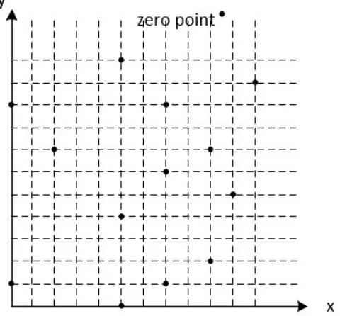
When we extend the elliptic curve to binary fieldGF(2m), thena,b∈GF(2m), and the equations in (2.8) and (2.9) should modular f(x) at the end of each equation, f(x) is the irreducible polynomial to generateGF(2m). In Fig 2.2, we see that the binary field elliptic curve presented in the coordinate graph is no longer a ”curve” with a set of infinitely points
in a real number field, instead, it consists of finite many points, the points being distributed
separately on the first quadrant and the non-negative axises of the plane coordinate graph.
The number of points involved in the elliptic curve E including O is called the order of
smallest positive integernsuch thatnG=O, every point on the curve as an order, and this order divides the order of the curve #E(GF(2m)). Commutativity and associativity are still satisfied for point operations in binary fields.
Figure 2.2: Elliptic curve over binary fieldGF(2m)
2.3.2
Finite Field Inversion Using Normal Basis
Finite field inversion operation is one of the basic operations of ECC computation. Assume
αbelongs to the finite fieldGF(2m)andαis represented using normal basis:
α=am−1θ2
m−1
+am−2θ2
m−2
+· · ·+a1θ2+a0θ (2.10)
Since for∀α∈GF(2m)there exists an order, denoted asord(α), and according to the
definition of the order, we have:
αord(α)=1 (2.11)
power ofnfrom both sides of equation (2.11), we could have:
(αord(α))n=α2
m−1
=1n=1 (2.12)
By dividingαwith both sides of equation (2.12), we could get the expression of inverse
α:
α−1=α2
m−2
(2.13)
Since 2x-power only needs a left shift, see equation (2.5) as a reference, we could take
the advantages of this property and obtain an efficient algorithm to compute finite field
inversion using normal basis representation. In Chapter 5, an efficient computation and
implementation of finite field inversion inGF(2163)is provided based on equation (2.13), using normal basis.
2.3.3
Elliptic Curve Cryptosystem
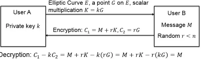
Figure 2.3: Encryption/decryption of elliptic curve cryptosystem
Elliptic curve cryptosystem (ECC) is a public-key cryptosystem that has a shorter key
size compared with RSA in same secure level. Suppose a base point Gon elliptic curve
E has ordern, then we could define the key pair as follows: the private keykis a positive integer smaller thann; the corresponding public keyKis a point on the curveE, whereK=
kGandKis computed by point scalar multiplication. The encryption/decryption operations can be described as follows:
Figure 2.4: Computation structure of ECC overGF(2m)
Gtogether with the public keyKto Bob (known as User B) for private communication; (2) If Bob has a message (known as the plaintext) and he wants to send it to Alice
privately. First, he maps or encodes the text to a point on E, denotes this point as M, different mapping methods can be found from [11], [23], [26] and [31]. Second, Bob
chooses a random number r <n and encrypts M with public key K and base point G, see equation (2.14). The two computed points (C1,C2)are knowns as the corresponding
ciphertext ofM. Third, Bob now sends the ciphertext(C1,C2)to Alice and this process can
be described as encryption;
(3) Alice receives the ciphertext (C1,C2) sent from Bob and decrypt them with the
private keyk, see equation (2.15), and finally she can read the secret message Bob sends. This process can be described as decryption.
Fig 2.3 shows the process of ECC encryption and decryption.
C1=M+rK, C2=rG (2.14)
From the above brief introduction of the ECC encryption/decryption operations, we
could see that the key issue to break this cryptosystem is to resolving the value of the
private key k from the equation K =kG. The fact is that knowing k and G to compute
K is simple by calculating a set of point addition and point doubling operations, however, knowing K and G to compute k is extremely hard when the size of the selected binary field is large. For this reason, this type of cryptosystem relies for its security level on the difficulty level of the elliptic curve discrete logarithm problem.
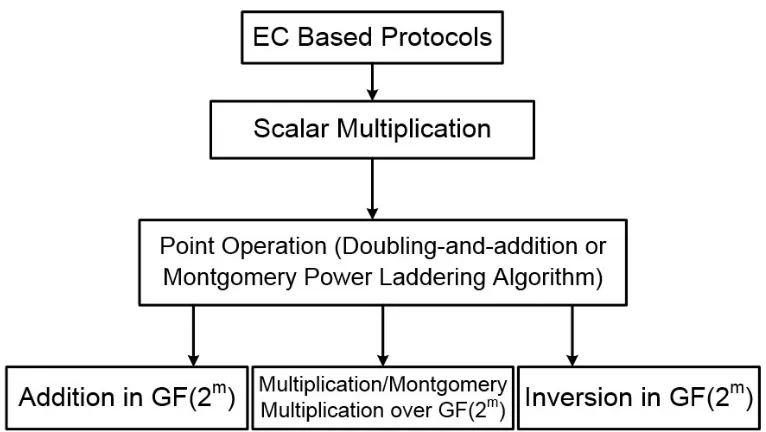
The computation of ECC contains four levels, see Fig 2.4. The top level is the ECC
itself. The major operation involved in ECC is the point scalar multiplication, and it is
the second level of ECC computation. A point scalar multiplication can be efficiently
calculated by a set of point doubling and point addition operations, for example 9P=
2(2(2P)) +Pcan be decomposed into four point doubling operations plus one point addi-tion operaaddi-tion. The computaaddi-tion of a point scalar multiplicaaddi-tion is similar to the
squaring-multiplying algorithm when calculating an exponentiation operation. Thus, the point
op-erations are the third level of ECC computation. The coordinate computation of the point operations, see equations (2.8) and (2.9), indicates that the basic operations of ECC
A Review of Existing Work
The existing Montgomery multipliers can be grouped into two types in terms of their
archi-tectures: general style including three sub-types: bit-serial [12], [22], [25], [28], bit-parallel [12], [15], [25] and digit-level [12], [28]; and systolic style [18], [20], [16], [27]. Bit-serial
multipliers load one operand bit-by-bit and the other operand in parallel. They usually
have the lowest gate complexity but require the longest time to process one operation; in
contrast, bit-parallel multipliers could reach the fastest processing speed by loading and
calculating both operands in parallel, but cost the most gate count when implementing.
Digit-level multipliers allow us to combine the advantages of both and seek the balance
between area and speed by processing one operand by constant bits each clock cycle and
the other operand in parallel. Systolic style multipliers consist of matrix-like rows of data
processing units (cells) known as a systolic array. These units are similar to central process-ing units, each unit shares the information with its neighbors. Systolic style architectures
are well suited to VLSI design due to the scalability, short inter-connection and highly
repetitive nature of the units. Our work will mainly focus on the architecture of digit-serial
Montgomery multipliers, and we will review some digit-serial polynomial multipliers and
digit-serial Montgomery multipliers first.
Montgomery multiplication was first applied to binary field multiplication in 1998 by
Koc [12], who reported the general algorithms of bit-serial (Table 3.1), bit-parallel
(Ta-ble 2.1) and digit-serial (Ta(Ta-ble 3.2) Montgomery multiplications. Koc [12] first showed
that by selecting the Montgomery factor R(x) =xm, the multiplication can be efficiently implemented in both bit-serial and digit-serial architectures. Besides, he proved that
ing digit-level Montgomery method for finite field multiplication could offer a much faster
processing speed compared with the standard digit-level multiplication.
Table 3.1: Algorithm of Bit-Serial Montgomery Multiplication Algorithm Bit-Serial Montgomery Multiplication Inputs: A(x),B(x)∈GF(2m), f(x)
Outputs: C(x) =A(x)×B(x)×x−m mod f(x)
Step 1: C(x) =0
fori=0 tom−1 do Step 2: C(x) =C(x) +aiB(x)
Step 3: C(x) =C(x) +c0f(x)
Step 4: C(x) =C(x)/x
Table 3.2: Algorithm of Digit-Serial Montgomery Multiplication, wheredis the digit size,
f00(x)f0(x) =1 modxd, C0(x) and f0(x)are the least significant digits ofC(x) and f(x), respectively
Algorithm Digit-Serial Montgomery Multiplication Inputs: A(x),B(x)∈GF(2m), f(x),f00(x)
Outputs: C(x) =A(x)×B(x)×x−m mod f(x)
Step 1: C(x) =0
fori=0 tos−1 do
Step 2: C(x) =C(x) +Ai(x)B(x) Step 2: M(x) =C0(x)f00(x) modxd
Step 3: C(x) =C(x) +M(x)f(x)
Step 4: C(x) =C(x)/xd
In 1998, Song proposed two different polynomial multiplier architectures: least
signif-icant digit (LSD) first and most signifsignif-icant digit (MSD) first, respectively. In 2005, Tang
reported a bit-parallel digit-serial multiplier inGF(2233), the architecture of the proposed
GF(2233)multiplier is shown in Fig 3.1. Tang’s architecture contains three main modules: a multiplier module to generate the partial productAj×B, a register to store the value of
C30−j−1, and a constant multiplier to calculate the product of x8×C30−j−1. The register
module can be implemented by a D-flipflop array, and since Tang used an irreducible
structure of partial product multiplier includes an AND gate section to logic AND each bit
of the digitAjwith operandB, a left-shift modular section to calculate the multiplied byxi
moduli operation, and finally an XOR tree section to add up all eight rows together. Tang’s
proposed digit-serial architecture can be treated as a landmark work since subsequent works
on digit-serial finite field multipliers are more or less optimizations or modifications of his
work.
Figure 3.1: (a)Tang’s architecture of GF(2233)multiplier [17] (b)Kumar’s architecture of
GF(2m)multiplier [19]
In 2006, Kumar proposed another polynomial multiplier in GF(2m) [19]. There are two major differences between Kumar’s work and Tang’s: one is that in the partial
prod-uct generator unit, after logic AND each bit of the digit Aj and left shift the bit-string by correspondingibits (0≤i≤d−1), Kumar directly added up all rows together with no re-duction operations, thus, the data-flow during processing hasm+d−1-bit bandwidth. As a consequence, Kumar added an extra module called the final reduction unit to process
mod-ular f(x) operation when the whole computation operation is over. The other difference is that Tang begins the multiplication from the most-significant-digit while Kumar begins
Figure 3.2: Tang’s architecture of partial product multiplier, generates the product ofAj×B [17]
operation for alld rows in the partial product module, but as a trade off, one extra clock cycle would be needed to complete the multiplication, another register for storing the value ofAxd mod f(x)is required, and in addition, the bandwidth of the data-flow was enlarged byd bits, see Fig 3.1(b).
In 2009, Meher [24] proposed a polynomial multiplier with a new structure of finite
field accumulator unit, which is the major difference between his work and the former
works reviewed. The block diagram of Meher’s work is presented in Fig 3.3. In the finite
field accumulator block, he used a T-flipflop array to implement the accumulate operation
instead of the structure using XOR gates and D-flipflop array. Besides, Meher also
com-bined the constant multiplier and partial product multiplier to generateAxd mod f(x)and
the same year, Hariri [25] published his work proving that, besidesR(x) =xm,R(x) =xm−1
could also be an efficient Montgomery factor in bit-serial structure, and later it was proved
by [28] that it can be applied to the digit-serial structure of Montgomery multiplications.
Figure 3.3: Meher’s block diagram of proposed field multiplier overGF(2m)[24]
The most recent digit-serial Montgomery multiplication architecture was that proposed
by [28] in 2011. A Linear Feedback Shift Register (LFSR) was used as the main building block to implement the Montgomery multiplication. In this work, the cases whenR(x) =
xm and R(x) =xm−1 are discussed. As reported, the proposed multipliers could adapt to different classes of irreducible polynomials such as general cases, all one polynomials,
trinomials and pentanomials, by changing the value of digit sized, the reported multipliers could also work as bit-serial multipliers or bit-parallel multipliers. The high flexibility of
their work is the critical contribution to the study of field multiplication. See Fig 3.4 of
[28]’s work.
In this thesis, a constraint condition is proposed to select the irreducible
pentanomi-als for the generation of finite field GF(2m). A most-significant-digit first and a least-significant-digit first digit-serial Montgomery multiplications are also proposed. The
ar-chitectures proposed in this work have some similarities with the works reported in [17]
and [24]. However, these two architectures have two major differences compared with the
proposed works in this thesis. First, the algorithms in [17] and [24] are about polynomial
Figure 3.4: Work reported in [28], (a)R(x) =xm, (b)R(x) =xm−1
be as good as or better than the existing works for the fields generated by the irreducible
Proposed Digit-serial Montgomery
Multipliers
In this chapter, the detailed algorithm and architecture of the proposed digit-serial
most-significant-digit first and least-most-significant-digit first Montgomery multiplier will be
intro-duced. The finite field is generated by irreducible pentanomial polynomials. The parameter
selection of the irreducible pentanomials is discussed, and a general condition to further
re-duce the time delay of the multiplier is proposed. The gate count and time delay of the
multiplier will be considered and analyzed when R(x) =xu, where the value of u is dif-ferent frommorm−1. Further discussions are is included. After this, comparisons with other types of digit-serial multipliers are provided. Finally, the FPGA implementation of
the proposed digit-serial Montgomery multipliers will be given, as well as its simulation
and compilation results.
4.1
Proposed Digit-Serial MSD First Montgomery
Multi-plier
In this section, a digit-serial MSD first Montgomery multiplier will be proposed. Two different architectures of the proposed multiplier are presented. In the first architecture,
the multiplication and reduction operations are processed in separate units; in the latter
architecture, the multiplication and reduction operations are combined and implemented in
one circuit block, and the performance is proved to be more efficient than architecture 1.
4.1.1
Algorithm
Consider the field elementsA,B, R, and their productCover GF(2m). Using the polyno-mial representation, we have:
A(x) =
m−1
∑
i=0
aixi, B(x) =
m−1
∑
i=0
bixi, R(x) =xl, C(x) =
m−1
∑
i=0
cixi. (4.1)
Here we use irreducible pentanomial f(x)to generateGF(2m), and f(x)is represented as:
f(x) =xm+xk3+xk2+xk1+1 (4.2) Since the idea in a digit-level multiplier is to compute a set of constant d bits from
B(x), wheredusually equals to a power of two (2, 4, 8, etc.) in practice, neither one bit at each clock cycle, nor all bits in parallel at the same time, we divideB(x)into blocks with equal length d, such that B(x) has sblocks, s=dm/de. Thus the digit-level polynomial representation ofB(x)can be written as:
B(x) =
s−1
∑
i=0
Bi(x)xid =
s−1
∑
i=0
d−1
∑
j=0
bid+jxid+j (4.3)
Note that, due to the fact that m may not always divisible by d, terms that generated by equation (4.3) with degree larger than m−1 or smaller than 0 should be set to 0. For example when m=233, d =8 and s=30, when i=29, B29(x)x232 = (b232+b233x1+
· · ·+b239x7)x232=b232x232.
Using the digit-level representation ofB(x), we can writeC(x)as:
C(x) =A(x)×
s−1
∑
i=0
Bi(x)xid×R−1(x) mod f(x) (4.4)
then we could use equation (4.5) to computeC(x):
C(x) =((A(x)Bs−1(x)x−lxd+A(x)Bs−2(x)x−l)xd+· · ·+A(x)B1(x)x−l)xd
+A(x)B0(x)x−l
(4.5)
Thus an algorithm of MSD-first Montgomery multiplication can be presented by Table 4.1.
Table 4.1: Digit-serial MSD-first Montgomery Multiplier (R(x) =xl), where 06l6d−1 Algorithm I Digit-serial MSD-first Montgomery Multiplier
Inputs: A(x),B0(x),B1(x), . . . ,Bs−1(x),f(x)
Outputs: C(x) =A(x)B(x)x−l mod f(x), 06l6d−1 Step 1: C(0)(x) =0
Fori=0 tos−1
Step 2: T(x) =A(x)Bs−1−i(x)x−l mod f(x)
Step 3: C(i+1)(x) =C(i)(x)xd+T(x) mod f(x)
Step 4: C(x) =C(s)(x)
Step 1 is the initialization step, register C is set to zero,C(x)(0) =0. In Step 2, the product ofA(x),Bs−i−1andx−lis computed, and the reduction operation is also processed in the same step. Then, in Step 3, the value generated in Step 2 is added with C(i)xd
mod f(x)and the result is stored back to the register. Wheni=s−1,C(s)will be obtained, the multiplier will provide the final result. Step 2 and 3 are processed in the same cycle,
also note that the calculation of Step 2 andC(i)(x)xdin Step 3 can be done in parallel.
4.1.2
General Architecture
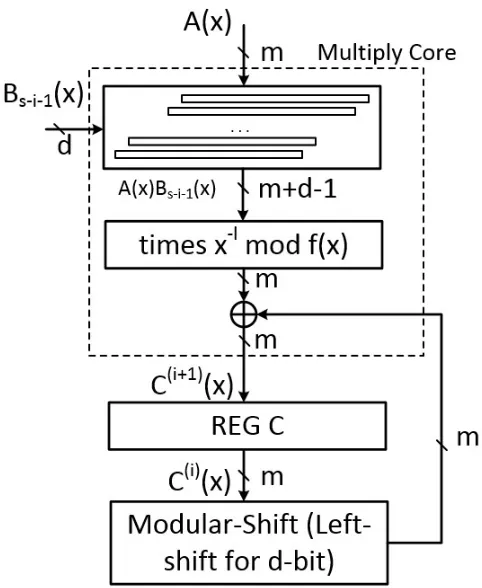
Fig 4.1 presents the block diagram of the proposed multiplier. The Multiplier Core unit
implements Step 2, also an XOR array is included in Multiply Core to implement the
addition operation in Step 3. Modular-Shift unit corresponds toC(i)xd mod f(x) in Step 3. The final result is provided in the register unit, REG C. By computing Step 2 in different orders, different architectures of the proposed multiplier can be obtained. This subsection
will present a general architecture.
In Step 2, if the product of A(x)andBs−i−1(x)is computed first, then the result times
x−l followed by the reduction operation mod f(x). The degree range ofA(x)Bs−i−1(x)x−l
Figure 4.1: Block diagram of proposed digit-serial MSD-first Montgomery multiplier when
R(x) =xl
from[−l,m+d−l−2]to[0,m−1]. It is clearly a two-side reduction operation: both side of polynomialA(x)Bs−i−1(x)x−l are beyond the bandwidth ofGF(2m). To further analyze
the computation of Step 2, we let A(x)Bs−i−1(x)x−l =TH(x) +TM(x) +TL(x), the degree range of TH(x),TM(x),TL(x) are [m,m+d−2−l],[0,m−1],[−l,−1], respectively. The reduction operation can be calculated as following equations:
Terms in TH(x): xm+d−2−l mod f(x) =xk3+d−2−l+xk2+d−2−l+xk1+d−2−l
+xd−2−l
.. .
xm+1 mod f(x) =xk3+1+xk2+1+xk1+1+x xm mod f(x) =xk3+xk2+xk1+1
Terms in TL(x): x−1 mod f(x) =xm−1+xk3−1+xk2−1+xk1−1 x−2 mod f(x) =xm−2+xk3−2+xk2−2+xk1−2
.. .
x−l mod f(x) =xm−l+xk3−l+xk2−l+xk1−l
Figure 4.2: General architecture of the proposed multiplier whenR(x) =xu
According to equation (4.6), fromTH(x)reduction, four extra bit-strings are generated, the degree range of these are: [k3,k3+d−2−l], [k2,k2+d−2−l], [k1,k1+d−2−l],
[0,d−2−l]. Similarly, another four bit-strings are generated byTL(x)reduction operation:
[m−l,m−1],[k3−l,k3−1],[k2−l,k2−1],[k1−l,k1−1]. Especially, bit-string[k3,k3+
d−2−l]and[k3−l,k3−1]can be combined into one bit-string with range[k3−l,k3+d−
2−l], in this way, all eight bit-strings can be transformed into five bit-string with degree range equal to: [m−l,m−1], [k3−l,k3+d−2−l], [k2−l,k2+d−2−l], [k1−l,k1+
d−2−l], [0,d−2−l], respectively. In order to avoid further reduction operation, the equations 4.6) must satisfy such conditions:
k3+d−2−l6m−1
After simplifying equation (4.7):
k36m+1+l−d
k1>l
(4.8)
From equation (4.6), we notice that we need to add up five bit-strings to TM(x), the gate usage is a constant number which is equal to 4(d−1). This fact indicates that the com-putation ofA(x)Bs−1−i(x)x−l mod f(x)will not generate extra gate delay when compared with the computation of A(x)Bs−1−i(x) mod f(x). However, the time delay varies with different value ofk1,k2,k3. To have the minimum time delayTX, the five bit-strings should have no overlapped parts, so the following conditions must be satisfied:
m−l>k3+d−2−l k3−l>k2+d−2−l
k2−l>k1+d−2−l k1−l>d−2−l
(4.9)
To sum up,ki(i=0,1,2,3) must satisfy:
ki+1−ki>d−1 (4.10)
Where k0=0 and k4=m, this condition is denoted as Constraint Condition 1. Besides,
from equation (4.10), k1 >d−1>l, and m−k3> d−1>d−1−l, this fact implies
that if equation (4.10) is applied when selecting the irreducible pentanomials of GF(2m), equation (4.8) will also be satisfied. The general architecture of the proposed multiplier is
presented in Fig 4.2.
In Multiply Core unit, the implementation ofA(x)Bs−i−1(x)is simple: operandA(x)is multiplied by each bit ofBs−1−i(x), and add up the terms with same degree. This block costs totallymdAND gates for the multiplication operation, and(m−1)(d−1)XOR gates for the field addition operations. The critical path delay of this unit islog2dTX+TA. The reduction operation costs 4(d−1)XOR gates and if Constraint Condition 1 is applied, the time delay isTX. Also, the XOR array needsm XOR gates and time delay isTX. Where
Multiply Core unit costsmdAND gates,(md+3d−3)XOR gates, and critical path delay isTA+ (2+log2d)TX
REG C unit updates the value ofC(i)(x)every clock cycle. This unit is implemented by a D-flipflop array, withmD-flipflops connected in parallel.
Modular-Shift unit computes the modular multiplicationC(i)(x)xd mod f(x). IfCd(i)(x)
represents the most significant d bits ofC(i), equation (4.11) can be used to present the computation ofC(i)(x)xd mod f(x).
C(i)(x)xd mod f(x) =Cd(i)(x)(xk3+xk2+xk1+1) +
m−1
∑
i=d
c(i−i)dxi (4.11)
To add up the five bit-strings together, in total 3dXOR gates will be needed, see Fig 4.3 for the implementation of equation (4.11) operation. By applying the condition obtained by
equation (4.10), whenki+1−ki>d, the four bit-strings,Cd(i)(x)xk3,C(i)
d (x)xk2, C
(i)
d (x)xk1, andCd(i)(x)will share no terms with same degree, thus the time delay of this circuit would beTX. For example, we letk2=k3−d, so the degree range ofCd(i)(x)xk3 is[k
3,k3+d−1]
while the degree range ofCd(i)(x)xk2is[k
2,k2+d−1]which equals[k2,k3−1]. Whenki+1−
ki =d−1, the degree range of Cd(i)(x)xk3, C(i)
d (x)xk2, C
(i)
d (x)xk1, and C
(i)
d (x) are [k3,m],
[k2,k3], [k1,k2] and [0,k1] respectively, it can be seen that each two of them having one
term with the same degree, thus the maximum depth of XORing these four bit strings is 2.
In addition, since the range ofCd(i)(x)xk3 is[k
3,m], the term with degreem needs another
reduction operation and this will generate three more bits for XORing. As a consequence,
the maximum depth of the XOR tree involved in this unit is 4, the time delay of this unit is
maximumlylog24TX =2TX, gate count is63d+3.
The critical path of this architecture is: Multiply Core1→REG C. The complexity of each block is presented in Table 4.2, and the complexity of the proposed multiplier is
presented in Table 4.3. In the tables,TDFF represents the delay of a D-flipflop.
Table 4.2: Complexity of each block of the proposed MSD-first Montgomery multiplier
Block Gate Count Time Delay
Multiply Core mdAND,md+3d−3 XOR TA+ (2+log2d)TX
REG C mD-flipflop TDFF
Modular-Shift 63d+3 XOR 62TX
Table 4.3: Complexity of proposed digit-serial MSD-first Montgomery multiplication (Al-gorithm I, general architecture, whenki+1−ki>d−1,k0=0,k4=mand 06l6d−1)
Work #AND #XOR #FF/Reg #CLK Critical path delay
MSD(Arch.1) md 6md+6d m s TA+ (2+log2d)TX+TDFF
4.1.3
Advanced Architecture
In this subsection, another architecture of the proposed multiplier one is introduced, the
structure of Multiply Core unit is different from the previous one.
If A(x)Bs−i−1(x)x−l mod f(x) is computed in a different order, see equation 4.12.
This indicates that A(x)x−l mod f(x), A(x)x−l+1 mod f(x), · · ·, A(x)xd−l−1 mod f(x)
are computed first, then multiply each term with the corresponding bit ofBs−1−i(x).
A(x)Bs−i−1(x)x−l mod f(x)
=A(x)
d−1
∑
j=0
b(s−i−1)d+jxjx−l mod f(x)
=
d−1
∑
j=0
(A(x)xj−l mod f(x))b(s−i−1)d+j
(4.12)
mod f(x)can be computed in this way:
A(x)x mod f(x) =am−1(xk3+xk2+xk1+1) +
m−1
∑
i=1
ai−1xi (4.13)
Fig 4.4 is a circuit diagram which implements equation (4.13): when input A(x), it will outputA(x)x mod f(x). If we connect two of such models in serial, the final output would
Figure 4.4: Model 1: multiply byxstructure
beA(x)x2 mod f(x), see Fig 4.5. In the same way, we could obtain each value ofA(x)xj−l
mod f(x), when j=l+1,l+2, . . . ,d−1.
Similarly, the computation ofA(x)/x mod f(x)is shown in equation (4.14)
A(x)/x mod f(x) =a0(xm+xk3+xk2+xk1)
m−2
∑
i=0
ai+1xi (4.14)
The implementation of equation (4.14) is shown in Fig 4.6. As a consequence, by
combin-ing multiples of the same circuit unit shown in Fig 4.6, each value ofA(x)xj−l mod f(x)
can be obtained, where j=0,1,2, . . . ,l−1.
If we apply both Model 1 shown in Fig. 4.4 and Model 2 shown in Fig 4.6 to the
implementation of equation (4.12), then the reduction operation is divided into two separate
Figure 4.5: Implementation of computationA(x)x2 mod f(x)
with x represent the circuit structure of Model 1, and blocks marked with x−1 represent Model 2. The architecture of the proposed multiplier is given in Fig 4.8. The depth of the
XOR tree isd+1, the XOR tree adds up alld products ofA(x)xj−lb(s−1−i)d+j mod f(x)
plus the value of REG C.
In order to have the least critical path delay of the Multiply Core unit, two groups of
conditions must be satisfied at the same time:
Condition 1:
m−l>k3−1
k3−l>k2−1
k2−l>k1−1
k1−l>−1
Figure 4.6: Model 2: multiply byx−1structure
Condition 2:
m>k3+d−2−l k3>k2+d−2−l
k2>k1+d−2−l k1>d−2−l
(4.16)
To sum up, Condition 1 iski+1−ki>l−1, and Condition 2 iski+1−ki>d−l−2, where
i=0,1,2,3,k0=0,k4=m. Thus, to have the least time delay,k3,k2,k1must satisfy:
ki+1−ki>max{l,d−l−1}, i=0,1,2,3and k0=0, k4=m (4.17)
This condition is denoted as Constraint Condition 2. More specifically, whenl>(d−1)/2,
ki+1−ki>l; whenl<(d−1)/2, ki+1−ki>d−l−1; whenl= (d−1)/2, ki+1−ki>
d/2−1/2, sincedusually an even number,ki+1−ki>d/2.
The remaining two units are completely the same with the architecture shown in Fig
4.2. REG C is implemented by a D-flipflop array, and Modular Shift unit costs a maximum
of 5dXOR gates, and 2TX time delay. The complexity of this architecture is shown in Table 4.4.
Figure 4.7: Implementation ofA(x)Bs−i−1(x)x−l mod f(x)
Figure 4.8: Advanced architecture of proposed multiplier
Table 4.4: Complexity of proposed digit-serial MSD-first Montgomery multiplication (Al-gorithm I, advanced architecture, when ki+1−ki>max{l,d−l−1}, i=0,1,2,3, k0=
0, k4=mand 06l6d−1)
Work #AND #XOR #FF/Reg #CLK Critical path delay MSD(Arch.2) md 6md+8d−3 m s TA+ (1+log2(d+1))TX+TDFF
latter architecture further extends the constraint condition of ki fromki+1−ki>d−1 to
ki+1−ki >max{l,d−l−1}, which indicates that more irreducible pentanomials can be applied to such Montgomery multiplication.
4.2
Proposed Digit-Serial LSD First Montgomery
Multi-plier
In this section, a digit-serial LSD first Montgomery Multiplier is proposed, and two
dif-ferent architectures are discussed when implementing the proposed multiplier. One of the
architectures uses separate multiplication and reduction units, while the other one uses a
linear-feedback-shift-register (LFSR) based structure.
4.2.1
Algorithm
SupposeA(x),B(x)∈GF(2m), in polynomial representation,B(x)is divided into digits of the same size:
B(x) =
s−1
∑
i=0
xidBi(x), where s=dm/de (4.18)
LetC(x) be the product of A(x), B(x), and a fixed element R−1(x) =x−u =x−sl, where
l >0, and l is an integer, the Montgomery multiplication can be computed by the way shown in equation (4.19). Based on equation (4.19), an algorithm of digit-serial LSD-first
C(x) =A(x)
s−1
∑
i=0
xidBi(x)x−sl
=A(x)B0(x)x−sl+A(x)xdB1(x)x−sl+A(x)x2dB2(x)x−sl+
· · ·+A(x)x(s−1)dBs−1(x)x−sl
=A(x)B0(x)x−sl+A(x)xd−lB1(x)x−(s−1)l+A(x)x2(d−l)B2(x)x−(s−2)l+
· · ·+A(x)x(s−1)(d−l)Bs−1(x)x−l
=(((A(x)B0(x)x−l+A(x)xd−lB1(x))x−l+A(x)x2(d−l)B2(x))x−l+
· · ·+A(x)x(s−1)(d−l)Bs−1(x))x−l
(4.19)
Table 4.5: Digit-serial LSD-first Montgomery Multiplier (R(x) =xsl), wherel>0 Algorithm II Digit-serial LSD-first Montgomery Multiplier
Input: A(x),Bi(x), f(x),i=0,1, . . . ,s−1
Outputs: C(x) =A(x)B(x)x−sl mod f(x), wheres=dm/de
Step 1: A(0)(x) =A(x),C(0)(x) =0 Fori=0 tos−1
Step 2: Ti(x) =A(i)(x)Bi(x)
Step 3: C(i+1)(x) = (C(i)(x) +Ti(x))/xl mod f(x)
Step 4: A(i+1)(x) =A(i)(x)xd−l mod f(x)
Step 5: C(x) =C(s)(x)
In Table 4.5, Step 1 is an initialization step, registersAandCare both set to zero; Step 2 computes the product of A(i)(x) and Bi(x); the result of Step 2 is forwarded to Step 3, after adding the value of registerC, a shift-to-right modulo operation is processed; Step 4 generatesAi+1(x)as the operand of next clock cycle; wheni=s−1, registerCwill output the final result at the end of the clock cycle.
4.2.2
General Architecture
The structure of the multiplier is shown in Fig 4.9. From top to bottom, block S1 computes
Step 4; REG A updates every clock cycle; the Multiply Core computes the product of
represents the operationTi(x) +C(i)(x); block S2 computes the operation multiply byx−l
modulo f(x); and finally, REG C stores the result of each clock cycle, and obtains the final product.
Figure 4.9: General architecture of the proposed digit-serial LSD first multiplier
When 06l6d−1, with the change ofl, the complexity of block S1 and S2 will also change, while the rest of the blocks remain the same. The implementation of Multiply Core
is simply logic AND each of the two operands, then add up the terms which have the same
degree. The two register unit includes only D-flipflops. Table 4.6 shows the complexity of
Multiply Core, REG A, REG C, and the XOR array: The same as the proposed MSD first
Table 4.6:
Block Gate Count Time Delay
Multiply Core & XOR array mdAND,md−d+1 XOR TA+log2(d+1)TX
REG A mD-flipflop TDFF
REG C mD-flipflop TDFF
equation is referred to equation (4.6):
xm+d−l−2 mod f(x) =xk3+d−l−2+xk2+d−l−2+xk1+d−l−2+xd−l−2
.. .
xm mod f(x) =xk3+xk2+xk1+1
x−1 mod f(x) =xm−1+xk3−1+xk2−1+xk1−1 x−2 mod f(x) =xm−2+xk3−2+xk2−2+xk1−2
.. .
x−l mod f(x) =xm−l+xk3−l+xk2−l+xk1−l
(4.20)
In order to further optimize the time delay, the condition of ki, i=1,2,3, must be satisfied, see equation (4.10) Specifically, whenl=0, the proposed multiplier would be a
Table 4.7: Complexity of digit-serial LSD Montgomery multiplication (Algorithm II, when 16l6d−1 andki+1−ki>d−1, k0=0, k4=m)
Work #AND #XOR #FF/Reg #CLK Critical path delay
LSD(16l6d−1) md md+3(2d−l−1) 2m s TA+ (1+log2(d+1))TX+TDFF
standard polynomial multiplier; whenl=d−1, the XOR gate cost is the lowest, which is equal tomd+3d.
Whenl =d, the architecture of the multiplier can be further optimized: sinced−l=
0, REG A and S1 can be saved, S2 computes multiply by x−d mod f(x), the reduction operation is only one-side. Table 4.8 gives the complexity summary whenl=d.
Table 4.8: Complexity of digit-level Montgomery multiplication (Algorithm II, whenl=d, andki+1−ki>d−1, k0=0, k4=m)
Work #AND #XOR #FF/Reg #CLK Critical path delay
LSD(l=d) md md+3d m s TA+ (1+log2(d+1))TX+TDFF
When l>d+1, sincel >l−d, we could predict that if we avoid multiple reduction operations in block S2, we could also avoid the multiple reduction in block S1. Besides,
sincel>d+1, the modulo f(x)operation is only one-side reduction.l must satisfyl6k1
Assume we divide(C(i)(x) +Ti(x))/xl into two parts:
(C(i)(x) +Ti(x))/xl=T(x) +TL(x) (4.21)
Then the reduction operation would be:
(C(i)(x) +Ti(x))/xl mod f(x) =TL(x)xm+TL(x)xk3+TL(x)xk2+TL(x)xk1+T(x) (4.22)
The degree range of each product in equation (4.22) is presented in Table 4.9.
Table 4.9: Degree range of each term of equation (4.22) Terms Degree Range
TL(x)xm [m−l,m−1]
TL(x)xk3 [k
3−l,k3−1]
TL(x)xk2 [k
2−l,k2−1]
TL(x)xk1 [k
1−l,k1−1]
T(x) [0,m+d−l−2]
From Table 4.9, obviously,m+d−l−2<m−1, thus, instead of usinglXOR gates to add termTL(x)xm−l toT(x), we only needd−1 XOR gates. Similarly, ifm+d−l−2<
k3−1, the XOR gate count of block S2 can be further reduced. Here we use a table to
present this result, see Table 4.10
Table 4.10: Value oflin terms of XOR gate usage of block S1
Conditions XOR Gate Count of Block S1
d+16l6min{m+d−k3−1,k1} 3l+d−1
m+d−k36l6min{m+d−k2−1,k1} 2l+2(d−1) + (m−k3)
m+d−k26l6min{m+d−k1−1,k1} l+3(d−1) + (m−k3) + (m−k2)
m+d−k16l6k1 4(d−1) + (m−k3) + (m−k2) + (m−k1)
Considering the time delay of block S2, when conditionsk3<m−l+1,k2<k3−l+1, andk1<k2−l+1 are all satisfied, the time delay isTX. To sum up,kimust satisfy:
ki+1−ki>l (4.23)
(4.23) has narrowed the condition. The complexities of the multiplier whenl>dis referred to Table 4.11.
Table 4.11: Complexity of digit-level Montgomery multiplication (Algorithm II, whenl>
d, andki+1−ki>l, k0=0, k4=m)
Work #AND #XOR #FF/Reg #CLK Critical path delay LSD(l>d) md 6md+6l−3d 2m s TA+ (1+log2(d+1))TX+TDFF
4.2.3
LFSR-Based Architecture
When 06l6d−1, a LFSR-based architecture can be provided.
Table 4.12: LFSR-Based Digit-serial LSD-first Montgomery Multiplier (R(x) =xsl), where 06l6d−1
Algorithm III LFSR-Based Digit-serial LSD-first Montgomery Multiplier Input: A(x),Bi(x), f(x),i=0,1, . . . ,s−1
Outputs: C(x) =A(x)B(x)x−sl mod f(x), wheres=dm/de
Step 1: A(0)(x) =A(x),C(0)(x) =0 Fori=0 tos−1
Step 2: Ti(x) =A(i)(x)Bi(x)/xl mod f(x) Step 3: C(i+1)(x) =C(i)(x)/xl mod f(x) +Ti(x)
Step 4: A(i+1)(x) =A(i)(x)xd−l mod f(x)
Step 5: C(x) =C(s)(x)
A minor change in Step 2 and 3 of Algorithm II is applied, and Table 4.12 presents the
new algorithm. In Algorithm III, Step 2 is computed as follows:
Ti(x) =
d−1
∑
j=0
A(i)xj−l mod f(x)·bid+j (4.24)
In equation (4.24),A(i)xj−l mod f(x)is computed first, then logic AND each bit ofBi(x). Since j =0,1,2, . . . ,d−1, when j = d−1, the corresponding term of A(i)xj−l equals
A(i)xd−l−1, also note that in Step 4 of Algorithm III, A(i)xd−l = A(i)xd−l−1·x, thus, by applying the circuit structure provided by Fig 4.4 and Fig 4.6, a LFSR based architecture
Figure 4.10: LFSR-based architecture of the proposed LSD Montgomery multiplier
In the architecture, register A andd−lModel 1 units consist of a linear feedback shift circuit, in addition, multiplyingxmodular operation and multiplyingx−1modular operation are divided into two separate parts. Each unit of Model 1 and Model 2 cost 3 XOR gates,
and in total, 3(d)dXOR gates. Thus, to have the minimum time delay of the architecture,
kimust satisfy:
ki+1−ki>max{l,d−l−1} (4.25)
wherei=0,1,2,3, k0=0, andk0=m. By applying the condition described in equation (4.25), the time delay of Multiplyx−l mod f(x)will beTX, and costs 3l XOR gates. The remaining blocks, REG A and REC C, have the same structure with as the general
![Figure 3.1: (a)Tang’s architecture of GFGF(2233) multiplier [17] (b)Kumar’s architecture of(2m) multiplier [19]](https://thumb-us.123doks.com/thumbv2/123dok_us/1407429.1173358/31.612.134.514.231.471/figure-tang-architecture-gfgf-multiplier-kumar-architecture-multiplier.webp)
![Figure 3.2: Tang’s architecture of partial product multiplier, generates the product of A j ×B[17]](https://thumb-us.123doks.com/thumbv2/123dok_us/1407429.1173358/32.612.155.492.110.404/figure-tang-architecture-partial-product-multiplier-generates-product.webp)
![Figure 3.3: Meher’s block diagram of proposed field multiplier over GF(2m) [24]](https://thumb-us.123doks.com/thumbv2/123dok_us/1407429.1173358/33.612.242.402.177.309/figure-meher-block-diagram-proposed-eld-multiplier-gf.webp)
![Figure 3.4: Work reported in [28], (a)R(x) = xm, (b)R(x) = xm−1](https://thumb-us.123doks.com/thumbv2/123dok_us/1407429.1173358/34.612.111.531.109.477/figure-work-reported-r-x-xm-r-xm.webp)